oil pressure YAMAHA FX HO CRUISER 2009 Owners Manual
[x] Cancel search | Manufacturer: YAMAHA, Model Year: 2009, Model line: FX HO CRUISER, Model: YAMAHA FX HO CRUISER 2009Pages: 106, PDF Size: 7.97 MB
Page 49 of 106
Features and functions
42
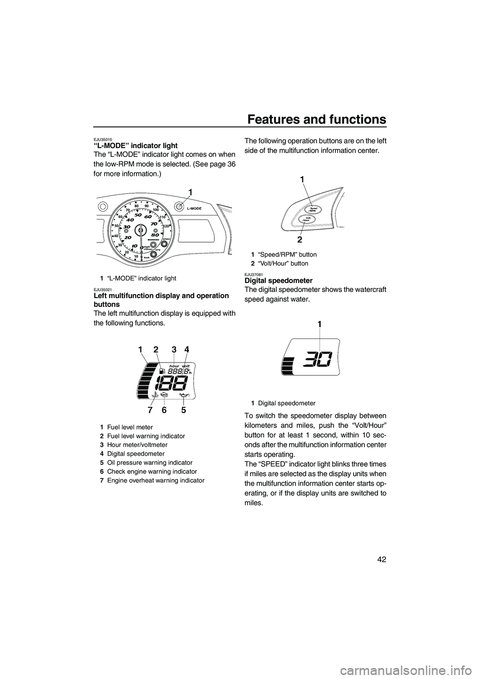
EJU35010“L-MODE” indicator light
The “L-MODE” indicator light comes on when
the low-RPM mode is selected. (See page 36
for more information.)
EJU35021Left multifunction display and operation
buttons
The left multifunction display is equipped with
the following functions.The following operation buttons are on the left
side of the multifunction information center.
EJU37081Digital speedometer
The digital speedometer shows the watercraft
speed against water.
To switch the speedometer display between
kilometers and miles, push the “Volt/Hour”
button for at least 1 second, within 10 sec-
onds after the multifunction information center
starts operating.
The “SPEED” indicator light blinks three times
if miles are selected as the display units when
the multifunction information center starts op-
erating, or if the display units are switched to
miles.1“L-MODE” indicator light
1Fuel level meter
2Fuel level warning indicator
3Hour meter/voltmeter
4Digital speedometer
5Oil pressure warning indicator
6Check engine warning indicator
7Engine overheat warning indicator
1“Speed/RPM” button
2“Volt/Hour” button
1Digital speedometer
UF2H70E0.book Page 42 Thursday, January 15, 2009 10:49 AM
Page 51 of 106
Features and functions
44
Voltmeter
The voltmeter is provided to display the volt-
age of the battery.
When the battery voltage is normal, the volt-
meter displays approximately 12 volts.
If the battery voltage is less than 8.0 volts,
“LO” is displayed on the voltmeter and if the
voltage is above 18.1 volts, “HI” is displayed
on the voltmeter. If “HI” or “LO” is displayed,
return to shore and, if necessary, have a
Yamaha dealer check the charging system
and the battery.
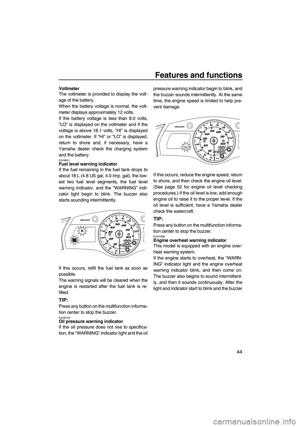
EJU36811Fuel level warning indicator
If the fuel remaining in the fuel tank drops to
about 18 L (4.8 US gal, 4.0 Imp. gal), the low-
est two fuel level segments, the fuel level
warning indicator, and the “WARNING” indi-
cator light begin to blink. The buzzer also
starts sounding intermittently.
If this occurs, refill the fuel tank as soon as
possible.
The warning signals will be cleared when the
engine is restarted after the fuel tank is re-
filled.
TIP:
Press any button on the multifunction informa-
tion center to stop the buzzer.
EJU35122Oil pressure warning indicator
If the oil pressure does not rise to specifica-
tion, the “WARNING” indicator light and the oilpressure warning indicator begin to blink, and
the buzzer sounds intermittently. At the same
time, the engine speed is limited to help pre-
vent damage.
If this occurs, reduce the engine speed, return
to shore, and then check the engine oil level.
(See page 52 for engine oil level checking
procedures.) If the oil level is low, add enough
engine oil to raise it to the proper level. If the
oil level is sufficient, have a Yamaha dealer
check the watercraft.
TIP:
Press any button on the multifunction informa-
tion center to stop the buzzer.
EJU37600Engine overheat warning indicator
This model is equipped with an engine over-
heat warning system.
If the engine starts to overheat, the “WARN-
ING” indicator light and the engine overheat
warning indicator blink, and then come on.
The buzzer also begins to sound intermittent-
ly, and then it sounds continuously. After the
light and indicator start to blink and the buzzer
UF2H70E0.book Page 44 Thursday, January 15, 2009 10:49 AM
Page 59 of 106
Operation
52
EJU32280Pre-operation check points EJU32331Engine compartment
WARNING
EWJ00460
Failure to ventilate the engine compart-
ment could result in a fire or explosion. Do
not start the engine if there is a fuel leak or
a loose electrical connection.
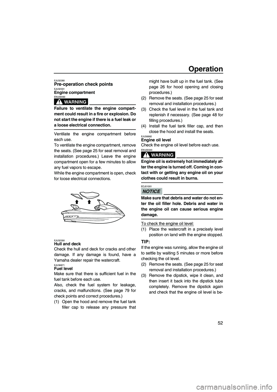
Ventilate the engine compartment before
each use.
To ventilate the engine compartment, remove
the seats. (See page 25 for seat removal and
installation procedures.) Leave the engine
compartment open for a few minutes to allow
any fuel vapors to escape.
While the engine compartment is open, check
for loose electrical connections.
EJU32350Hull and deck
Check the hull and deck for cracks and other
damage. If any damage is found, have a
Yamaha dealer repair the watercraft.
EJU36871Fuel level
Make sure that there is sufficient fuel in the
fuel tank before each use.
Also, check the fuel system for leakage,
cracks, and malfunctions. (See page 79 for
check points and correct procedures.)
(1) Open the hood and remove the fuel tank
filler cap to release any pressure thatmight have built up in the fuel tank. (See
page 26 for hood opening and closing
procedures.)
(2) Remove the seats. (See page 25 for seat
removal and installation procedures.)
(3) Check the fuel level in the fuel tank and
replenish if necessary. (See page 48 for
filling procedures.)
(4) Install the fuel tank filler cap, and then
close the hood and install the seats.
EJU36882Engine oil level
Check the engine oil level before each use.
WARNING
EWJ00340
Engine oil is extremely hot immediately af-
ter the engine is turned off. Coming in con-
tact with or getting any engine oil on your
clothes could result in burns.
NOTICE
ECJ01001
Make sure that debris and water do not en-
ter the oil filler hole. Debris and water in
the engine oil can cause serious engine
damage.
To check the engine oil level:
(1) Place the watercraft in a precisely level
position on land with the engine stopped.
TIP:
If the engine was running, allow the engine oil
to settle by waiting 5 minutes or more before
checking the oil level.
(2) Remove the seats. (See page 25 for seat
removal and installation procedures.)
(3) Remove the dipstick, wipe it clean, and
then insert it back into the dipstick tube
completely. Remove the dipstick again
and check that the engine oil level is be-
UF2H70E0.book Page 52 Thursday, January 15, 2009 10:49 AM
Page 97 of 106
Trouble recovery
90
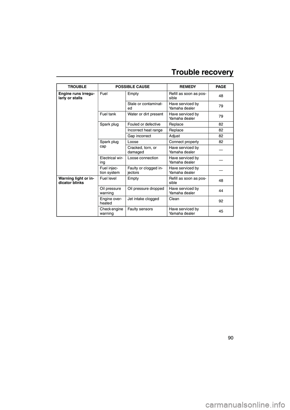
Engine runs irregu-
larly or stallsFuel Empty Refill as soon as pos-
sible48
Stale or contaminat-
edHave serviced by
Yamaha dealer79
Fuel tank Water or dirt present Have serviced by
Yamaha dealer79
Spark plug Fouled or defective Replace 82
Incorrect heat range Replace 82
Gap incorrect Adjust 82
Spark plug
capLoose Connect properly 82
Cracked, torn, or
damagedHave serviced by
Yamaha dealer—
Electrical wir-
ingLoose connection Have serviced by
Yamaha dealer—
Fuel injec-
tion systemFaulty or clogged in-
jectorsHave serviced by
Yamaha dealer—
Warning light or in-
dicator blinksFuel level Empty Refill as soon as pos-
sible48
Oil pressure
warningOil pressure dropped Have serviced by
Yamaha dealer44
Engine over-
heatedJet intake clogged Clean
92
Check engine
warningFaulty sensors Have serviced by
Yamaha dealer45 TROUBLE POSSIBLE CAUSE REMEDY PAGE
UF2H70E0.book Page 90 Thursday, January 15, 2009 10:49 AM
Page 98 of 106
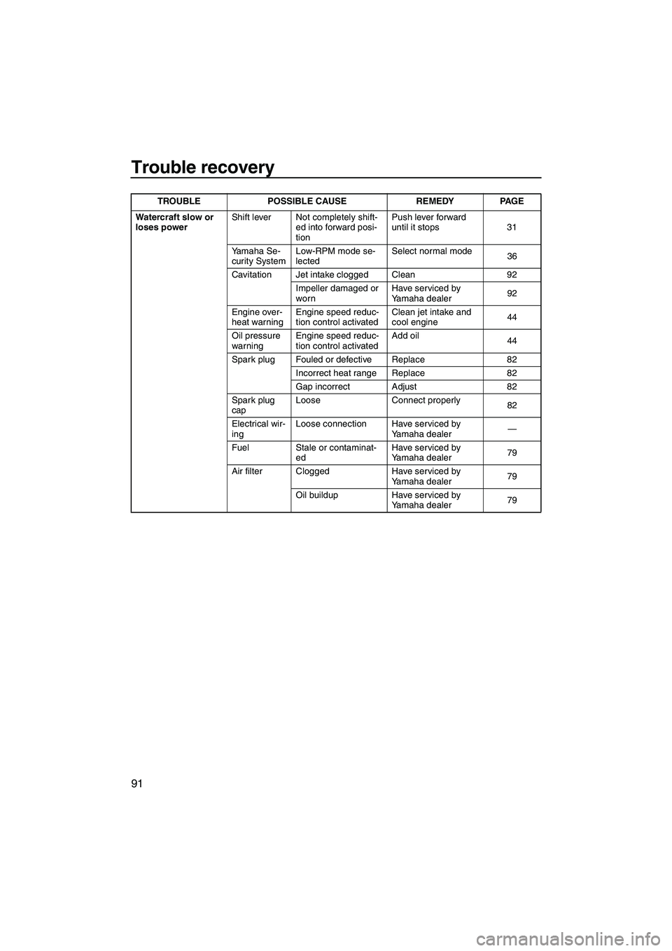
Trouble recovery
91
Watercraft slow or
loses powerShift lever Not completely shift-
ed into forward posi-
tionPush lever forward
until it stops 31
Yamaha Se-
curity SystemLow-RPM mode se-
lectedSelect normal mode
36
Cavitation Jet intake clogged Clean 92
Impeller damaged or
wornHave serviced by
Yamaha dealer92
Engine over-
heat warningEngine speed reduc-
tion control activatedClean jet intake and
cool engine44
Oil pressure
warningEngine speed reduc-
tion control activatedAdd oil
44
Spark plug Fouled or defective Replace 82
Incorrect heat range Replace 82
Gap incorrect Adjust 82
Spark plug
capLoose Connect properly
82
Electrical wir-
ingLoose connection Have serviced by
Yamaha dealer—
Fuel Stale or contaminat-
edHave serviced by
Yamaha dealer79
Air filter Clogged Have serviced by
Yamaha dealer79
Oil buildup Have serviced by
Yamaha dealer79 TROUBLE POSSIBLE CAUSE REMEDY PAGE
UF2H70E0.book Page 91 Thursday, January 15, 2009 10:49 AM
Page 104 of 106
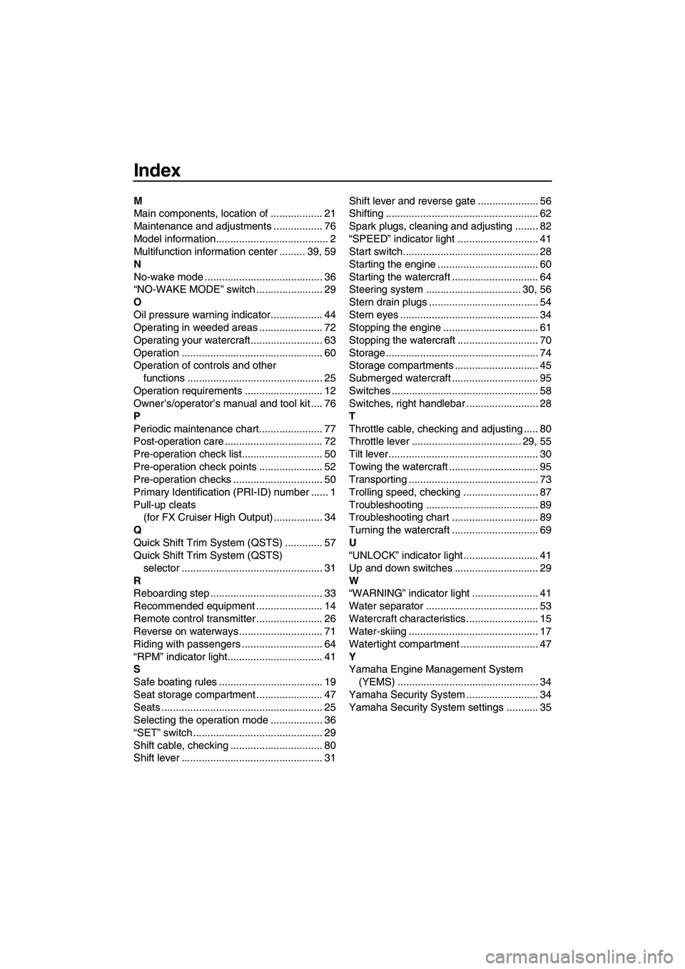
Index
M
Main components, location of .................. 21
Maintenance and adjustments ................. 76
Model information....................................... 2
Multifunction information center ......... 39, 59
N
No-wake mode ......................................... 36
“NO-WAKE MODE” switch ....................... 29
O
Oil pressure warning indicator.................. 44
Operating in weeded areas ...................... 72
Operating your watercraft......................... 63
Operation ................................................. 60
Operation of controls and other
functions ............................................... 25
Operation requirements ........................... 12
Owner’s/operator’s manual and tool kit .... 76
P
Periodic maintenance chart...................... 77
Post-operation care .................................. 72
Pre-operation check list............................ 50
Pre-operation check points ...................... 52
Pre-operation checks ............................... 50
Primary Identification (PRI-ID) number ...... 1
Pull-up cleats
(for FX Cruiser High Output) ................. 34
Q
Quick Shift Trim System (QSTS) ............. 57
Quick Shift Trim System (QSTS)
selector ................................................. 31
R
Reboarding step ....................................... 33
Recommended equipment ....................... 14
Remote control transmitter ....................... 26
Reverse on waterways ............................. 71
Riding with passengers ............................ 64
“RPM” indicator light................................. 41
S
Safe boating rules .................................... 19
Seat storage compartment ....................... 47
Seats ........................................................ 25
Selecting the operation mode .................. 36
“SET” switch ............................................. 29
Shift cable, checking ................................ 80
Shift lever ................................................. 31Shift lever and reverse gate ..................... 56
Shifting ..................................................... 62
Spark plugs, cleaning and adjusting ........ 82
“SPEED” indicator light ............................ 41
Start switch............................................... 28
Starting the engine ................................... 60
Starting the watercraft .............................. 64
Steering system ................................. 30, 56
Stern drain plugs ...................................... 54
Stern eyes ................................................ 34
Stopping the engine ................................. 61
Stopping the watercraft ............................ 70
Storage..................................................... 74
Storage compartments ............................. 45
Submerged watercraft .............................. 95
Switches ................................................... 58
Switches, right handlebar ......................... 28
T
Throttle cable, checking and adjusting ..... 80
Throttle lever ...................................... 29, 55
Tilt lever .................................................... 30
Towing the watercraft ............................... 95
Transporting ............................................. 73
Trolling speed, checking .......................... 87
Troubleshooting ....................................... 89
Troubleshooting chart .............................. 89
Turning the watercraft .............................. 69
U
“UNLOCK” indicator light .......................... 41
Up and down switches ............................. 29
W
“WARNING” indicator light ....................... 41
Water separator ....................................... 53
Watercraft characteristics ......................... 15
Water-skiing ............................................. 17
Watertight compartment ........................... 47
Y
Yamaha Engine Management System
(YEMS) ................................................. 34
Yamaha Security System ......................... 34
Yamaha Security System settings ........... 35
UF2H70E0.book Page 2 Thursday, January 15, 2009 10:49 AM