YAMAHA GRIZZLY 700 2020 Owners Manual
GRIZZLY 700 2020
YAMAHA
YAMAHA
https://www.carmanualsonline.info/img/51/50443/w960_50443-0.png
YAMAHA GRIZZLY 700 2020 Owners Manual
Trending: steering, coolant capacity, towing capacity, tires, checking oil, replace headlight, oil viscosity
Page 111 of 182
9-8
9
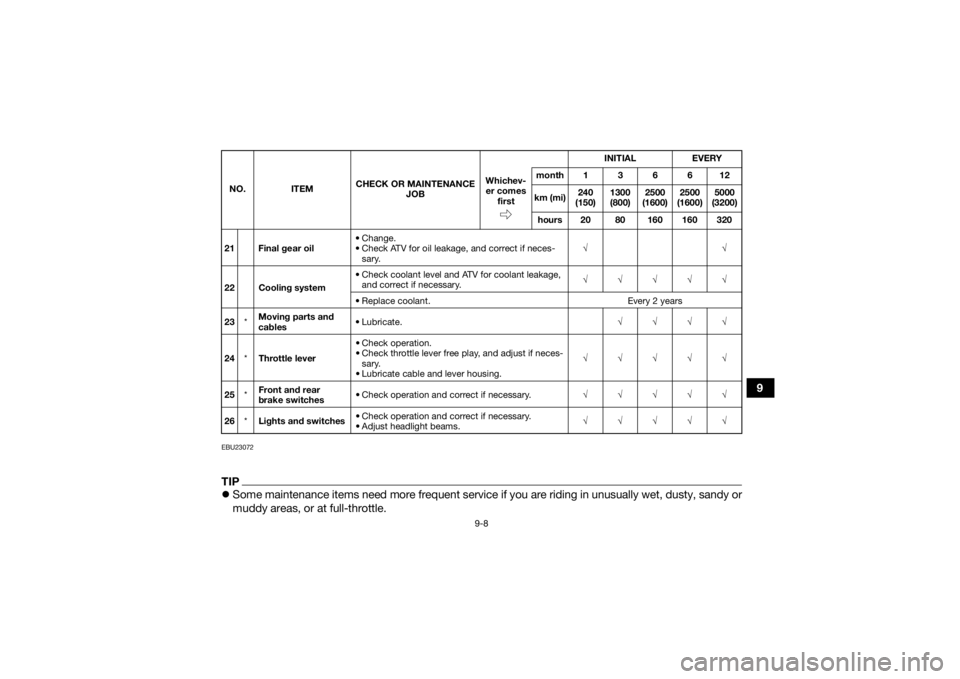
EBU23072TIPSome maintenance items need more frequent service if you are riding in unusually wet, dusty, sandy or
muddy areas, or at full-throttle.21 Final gear oil • Change.
• Check ATV for oil leakage, and correct if neces-
sary. √√
22 Cooling system • Check coolant level and ATV for coolant leakage,
and correct if necessary. √√√√√
• Replace coolant. Every 2 years
23 *Moving parts and
cables •Lubricate.
√√√√
24 *Throttle lever • Check operation.
• Check throttle lever free play, and adjust if neces-
sary.
• Lubricate cable and lever housing. √√√√√
25 *Front and rear
brake switches • Check operation and correct if necessary.
√√√√√
26 *Lights and switches • Check operation and correct if necessary.
• Adjust headlight beams. √√√√√
NO.
ITEM CHECK OR MAINTENANCE
JOB INITIAL
EVERY
Whichev- er comes first month136612
km (mi) 240
(150) 1300
(800) 2500
(1600) 2500
(1600) 5000
(3200)
hours 20 80 160 160 320UBDE60E0.book Page 8 Monday, April 22, 2019 4:12 PM
Page 112 of 182
9-9
9
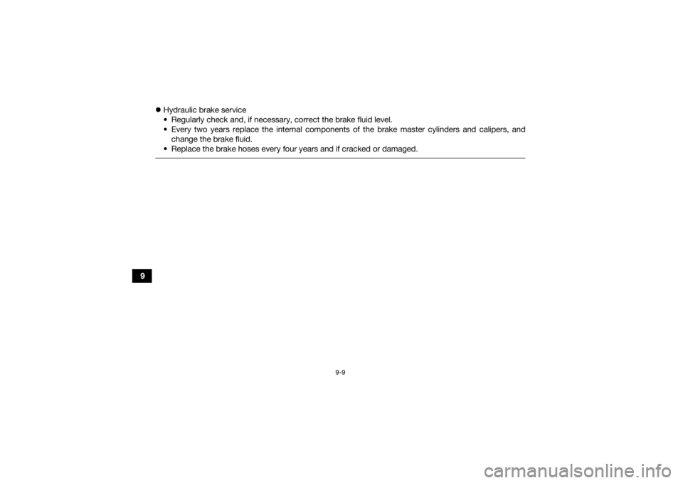
Hydraulic brake service
• Regularly check and, if necessary, correct the brake fluid level.
• Every two years replace the internal components of the brake master cylinders and calipers, and
change the brake fluid.
• Replace the brake hoses every four years and if cracked or damaged.
UBDE60E0.book Page 9 Monday, April 22, 2019 4:12 PM
Page 113 of 182
9-10
9
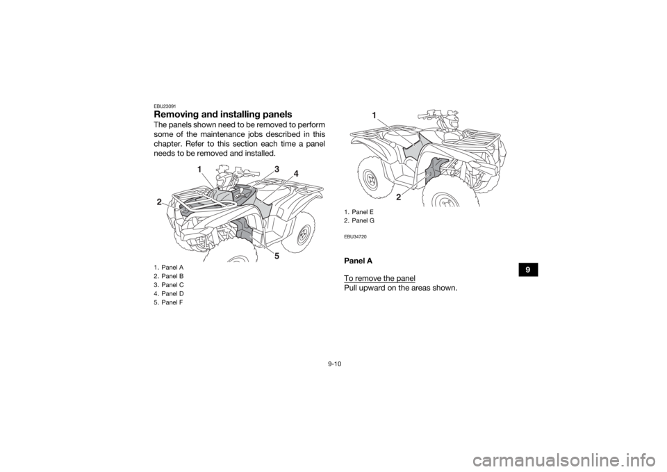
EBU23091Removing and installing panelsThe panels shown need to be removed to perform
some of the maintenance jobs described in this
chapter. Refer to this section each time a panel
needs to be removed and installed.
EBU34720Panel A
To remove the panelPull upward on the areas shown.
1. Panel A
2. Panel B
3. Panel C
4. Panel D
5. Panel F2
1
3
4
5
1. Panel E
2. Panel G
2
1
UBDE60E0.book Page 10 Monday, April 22, 2019 4:12 PM
Page 114 of 182
9-11
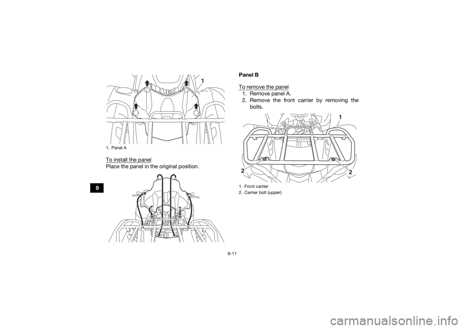
9To install the panel
Place the panel in the original position. Panel B
To remove the panel
1. Remove panel A.
2. Remove the front carrier by removing the
bolts.
1. Panel A
1
1. Front carrier
2. Carrier bolt (upper)
1
2
2
UBDE60E0.book Page 11 Monday, April 22, 2019 4:12 PM
Page 115 of 182
9-12
9
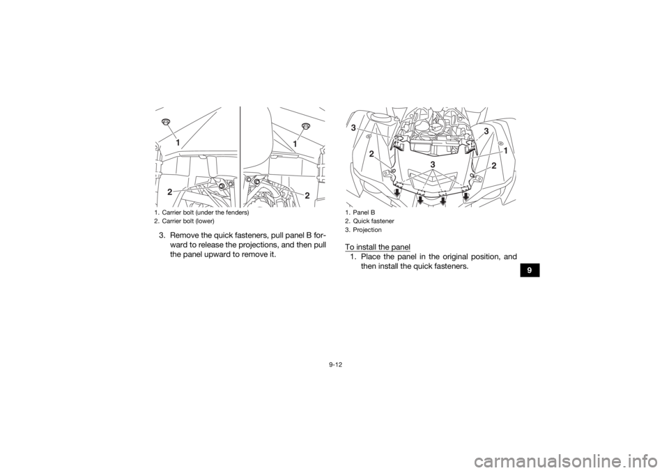
3. Remove the quick fasteners, pull panel B for-
ward to release the projections, and then pull
the panel upward to remove it. To install the panel
1. Place the panel in the original position, and
then install the quick fasteners.
1. Carrier bolt (under the fenders)
2. Carrier bolt (lower)
1
2
2
1
1. Panel B
2. Quick fastener
3. Projection3
3
1
2
3
2
UBDE60E0.book Page 12 Monday, April 22, 2019 4:12 PM
Page 116 of 182
9-13
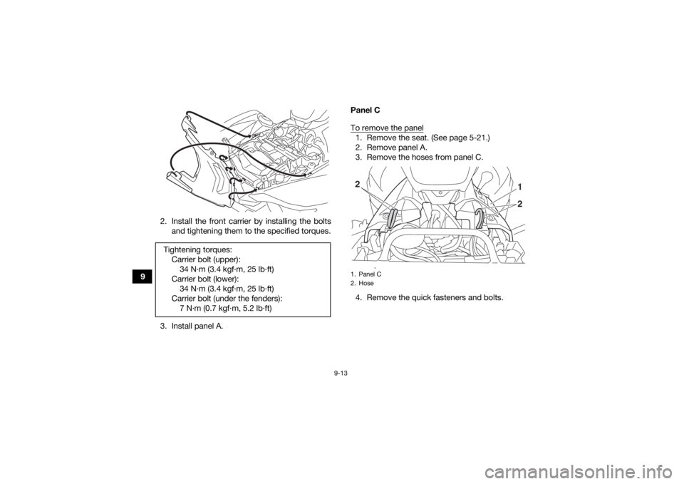
92. Install the front carrier by installing the bolts
and tightening them to the specified torques.
3. Install panel A. Panel C
To remove the panel
1. Remove the seat. (See page 5-21.)
2. Remove panel A.
3. Remove the hoses from panel C.
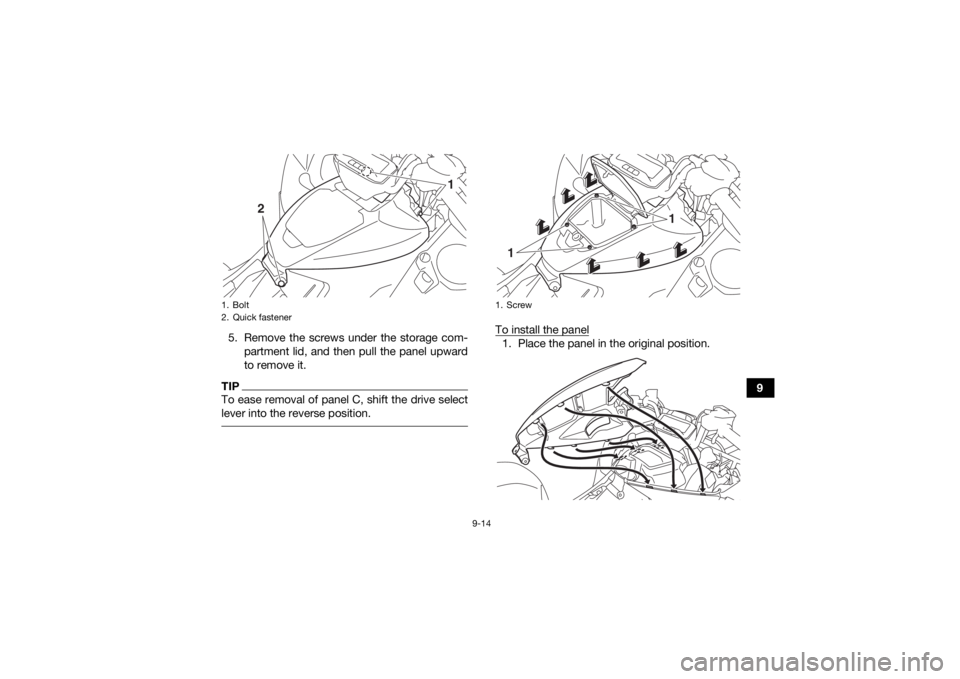
4. Remove the quick fasteners and bolts.
Tightening torques:
Carrier bolt (upper):34 N·m (3.4 kgf·m, 25 lb·ft)
Carrier bolt (lower): 34 N·m (3.4 kgf·m, 25 lb·ft)
Carrier bolt (under the fenders): 7 N·m (0.7 kgf·m, 5.2 lb·ft)1. Panel C
2. Hose
21
2
UBDE60E0.book Page 13 Monday, April 22, 2019 4:12 PM
Page 117 of 182
9-14
9
5. Remove the screws under the storage com-
partment lid, and then pull the panel upward
to remove it.
TIPTo ease removal of panel C, shift the drive select
lever into the reverse position.
To install the panel1. Place the panel in the original position.
1. Bolt
2. Quick fastener
1
2
1. Screw
1
1
UBDE60E0.book Page 14 Monday, April 22, 2019 4:12 PM
Page 118 of 182
9-15
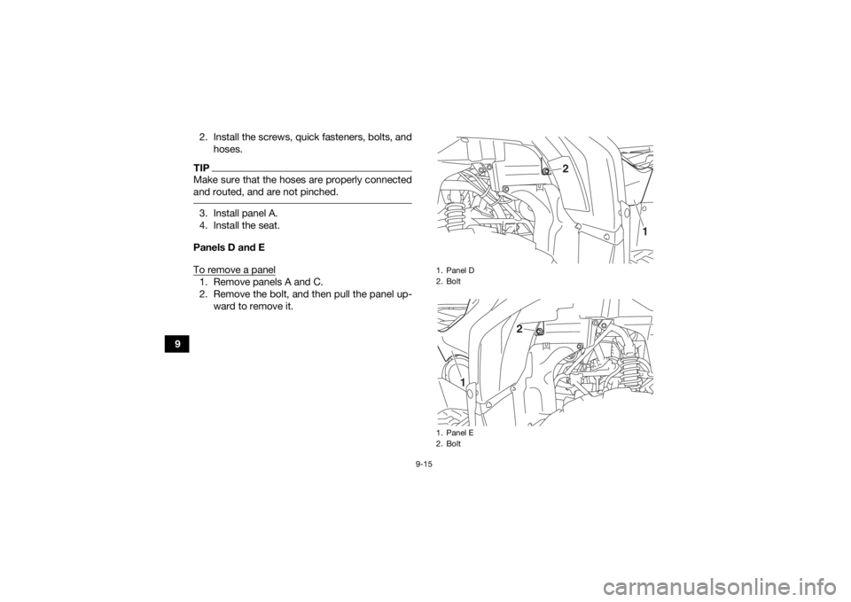
92. Install the screws, quick fasteners, bolts, and
hoses.
TIPMake sure that the hoses are properly connected
and routed, and are not pinched. 3. Install panel A.
4. Install the seat.
Panels D and E
To remove a panel1. Remove panels A and C.
2. Remove the bolt, and then pull the panel up- ward to remove it.
1. Panel D
2. Bolt
1. Panel E
2. Bolt
1
2
1
2
UBDE60E0.book Page 15 Monday, April 22, 2019 4:12 PM
Page 119 of 182
9-16
9
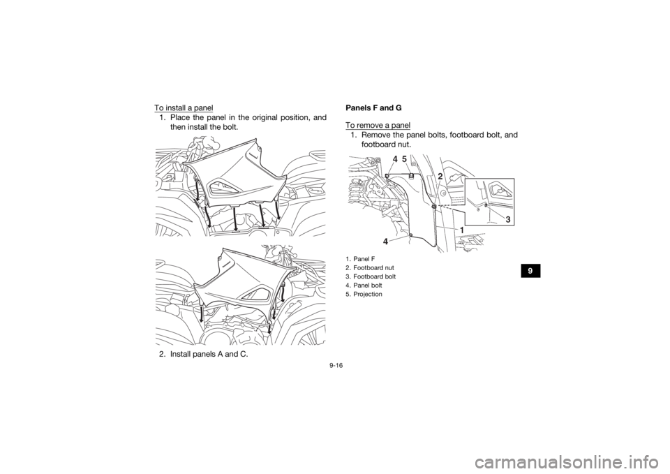
To install a panel
1. Place the panel in the original position, and
then install the bolt.
2. Install panels A and C. Panels F and G
To remove a panel
1. Remove the panel bolts, footboard bolt, and
footboard nut.1. Panel F
2. Footboard nut
3. Footboard bolt
4. Panel bolt
5. Projection
UBDE60E0.book Page 16 Monday, April 22, 2019 4:12 PM
Page 120 of 182
9-17
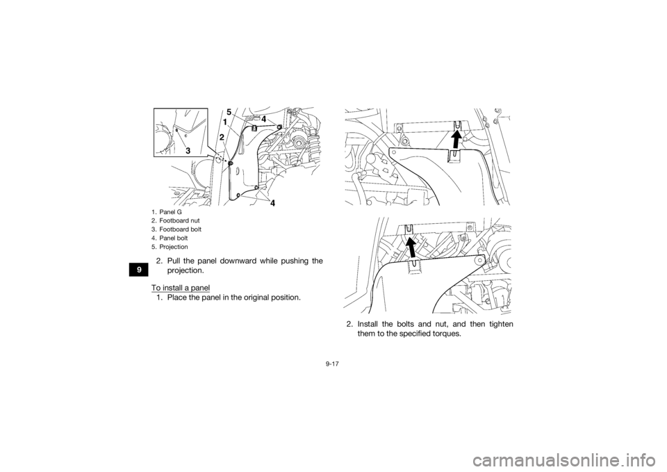
92. Pull the panel downward while pushing the
projection.
To install a panel
1. Place the panel in the original position.
2. Install the bolts and nut, and then tightenthem to the specified torques.1. Panel G
2. Footboard nut
3. Footboard bolt
4. Panel bolt
5. ProjectionUBDE60E0.book Page 17 Monday, April 22, 2019 4:12 PM
Trending: tow, fuel tank capacity, replace headlight, cooling, coolant reservoir, belt, wheel size
