YAMAHA NMAX 125 2021 Owner's Guide
Manufacturer: YAMAHA, Model Year: 2021, Model line: NMAX 125, Model: YAMAHA NMAX 125 2021Pages: 114, PDF Size: 10.63 MB
Page 31 of 114
Stop and Start System
4-3
4
WARNING
EWA18731
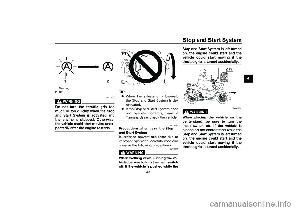
Do not turn the throttle grip too
much or too quickly when the Stop
and Start System is activated and
the engine is stopped. Otherwise,
the vehicle could start moving unex-
pectedly after the engine restarts.
TIPWhen the sidestand is lowered,
the Stop and Start System is de-
activated.
If the Stop and Start System does
not operate correctly, have a
Yamaha dealer check the vehicle.
EAU76711
Precautions when using the Stop
and Start System
In order to prevent accidents due to
improper operation, carefully read and
observe the following precautions.
WARNING
EWA18741
When walking while pushing the ve-
hicle, be sure to turn the main switch
off. If the vehicle is pushed while theStop and Start System is left turned
on, the engine could start and the
vehicle could start moving if the
throttle grip is turned accidentally.
WARNING
EWA18751
When placing the vehicle on the
centerstand, be sure to turn the
main switch off. If the vehicle is
placed on the centerstand while the
Stop and Start System is left turned
on, the engine could start and the
vehicle could start moving if the
throttle grip is turned accidentally.
1. Flashing
2. Off
1
2
A
OFF
UBALE0E0.book Page 3 Wednesday, September 30, 2020 1:37 PM
Page 32 of 114
Stop and Start System
4-4
4
WARNING
EWA18771
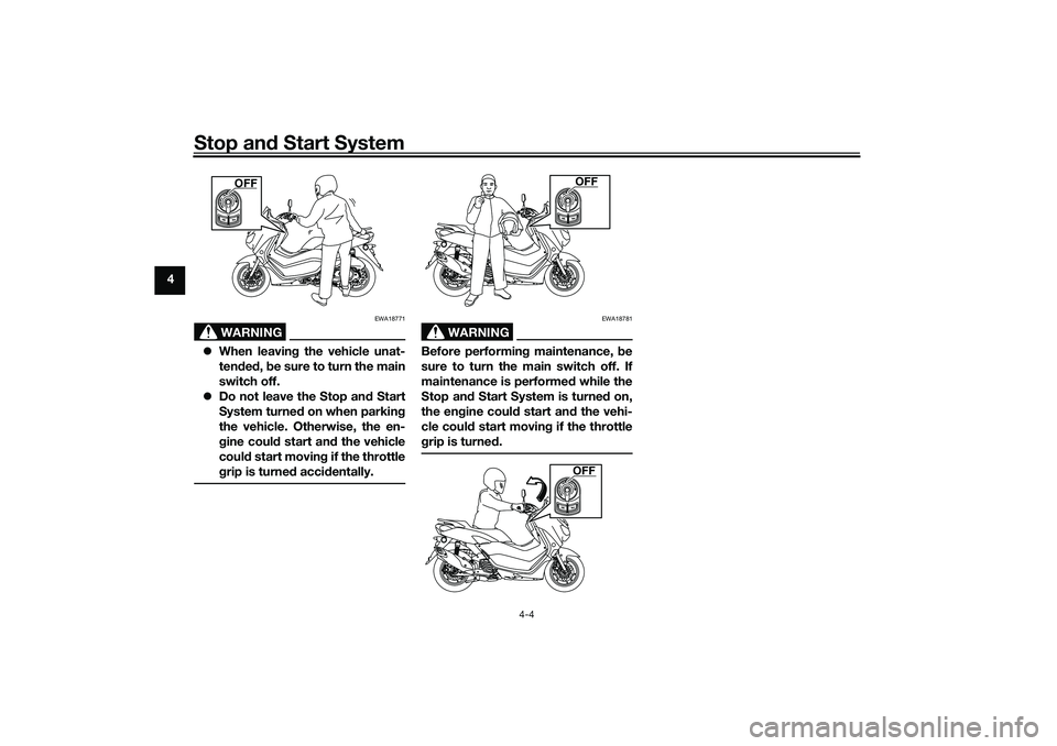
When leaving the vehicle unat-
tended, be sure to turn the main
switch off.
Do not leave the Stop and Start
System turned on when parking
the vehicle. Otherwise, the en-
gine could start and the vehicle
could start moving if the throttle
grip is turned accidentally.
WARNING
EWA18781
Before performing maintenance, be
sure to turn the main switch off. If
maintenance is performed while the
Stop and Start System is turned on,
the engine could start and the vehi-
cle could start moving if the throttle
grip is turned.
OFF
OFFOFF
UBALE0E0.book Page 4 Wednesday, September 30, 2020 1:37 PM
Page 33 of 114
Special features
5-1
5
EAUN3012
CCU (Communication Control
Unit)This model is equipped with a CCU
that allows your vehicle and smart-
phone to connect using Bluetooth
wireless technology and the MyRide
App.
With this connection, notifications from
apps, incoming phone calls and
missed calls are signaled to you, and
the battery level of your smartphone is
displayed.
WARNING
EWAN0070
Always stop the vehicle before
operating your smartphone.
Never take your hands off the
handlebars while riding.
Always concentrate on riding by
keeping your eyes and mind on
the road.NOTICE
ECAN0150
The Bluetooth connection may not
work in the following situations.In a location exposed to strong
radio waves or other electro-
magnetic noise.
At facilities nearby that are
emitting strong radio waves (TV
or radio towers, power plants,
broadcasting stations, airports,
etc.).
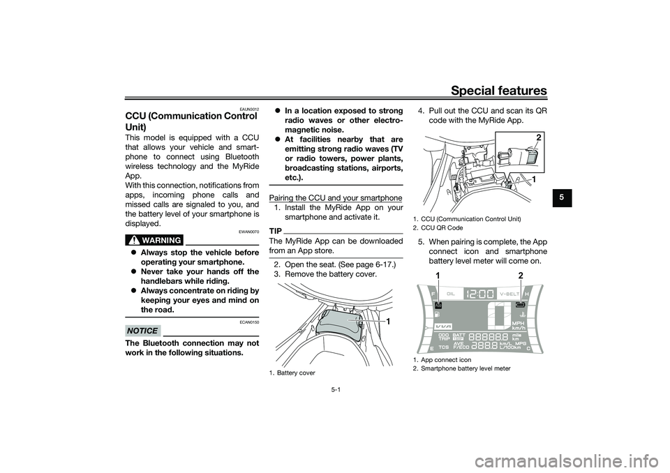
Pairing the CCU and your smartphone1. Install the MyRide App on your
smartphone and activate it.TIPThe MyRide App can be downloaded
from an App store.2. Open the seat. (See page 6-17.)
3. Remove the battery cover.4. Pull out the CCU and scan its QR
code with the MyRide App.
5. When pairing is complete, the App
connect icon and smartphone
battery level meter will come on.1. Battery cover
1
1. CCU (Communication Control Unit)
2. CCU QR Code
1. App connect icon
2. Smartphone battery level meter
12
1
2
UBALE0E0.book Page 1 Wednesday, September 30, 2020 1:37 PM
Page 34 of 114
Special features
5-2
5
TIPOnce paired, the smartphone is
registered in the CCU. The next
time the vehicle is turned on and
the MyRide App is active, the con-
nection will be automatically exe-
cuted.
Only one smartphone can be con-
nected to the CCU at a time.
If more than one phone has been
registered in the CCU, then the
first phone within reach will be
connected.
UBALE0E0.book Page 2 Wednesday, September 30, 2020 1:37 PM
Page 35 of 114
Instrument and control functions
6-1
6
EAU77123
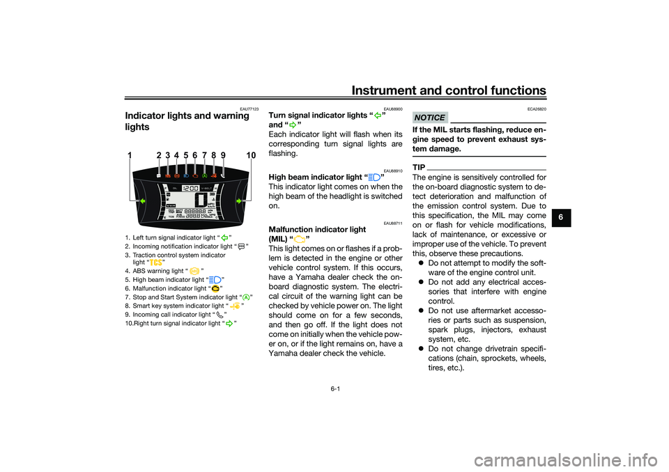
Indicator lights and warning
lights
EAU88900
Turn signal indicator lights “ ”
and“”
Each indicator light will flash when its
corresponding turn signal lights are
flashing.
EAU88910
High beam indicator light “ ”
This indicator light comes on when the
high beam of the headlight is switched
on.
EAU88711
Malfunction indicator light
(MIL) “ ”
This light comes on or flashes if a prob-
lem is detected in the engine or other
vehicle control system. If this occurs,
have a Yamaha dealer check the on-
board diagnostic system. The electri-
cal circuit of the warning light can be
checked by vehicle power on. The light
should come on for a few seconds,
and then go off. If the light does not
come on initially when the vehicle pow-
er on, or if the light remains on, have a
Yamaha dealer check the vehicle.
NOTICE
ECA26820
If the MIL starts flashing, reduce en-
gine speed to prevent exhaust sys-
tem damage.TIPThe engine is sensitively controlled for
the on-board diagnostic system to de-
tect deterioration and malfunction of
the emission control system. Due to
this specification, the MIL may come
on or flash for vehicle modifications,
lack of maintenance, or excessive or
improper use of the vehicle. To prevent
this, observe these precautions.
Do not attempt to modify the soft-
ware of the engine control unit.
Do not add any electrical acces-
sories that interfere with engine
control.
Do not use aftermarket accesso-
ries or parts such as suspension,
spark plugs, injectors, exhaust
system, etc.
Do not change drivetrain specifi-
cations (chain, sprockets, wheels,
tires, etc.).
1. Left turn signal indicator light “ ”
2. Incoming notification indicator light “ ”
3. Traction control system indicator
light “ ”
4. ABS warning light “ ”
5. High beam indicator light “ ”
6. Malfunction indicator light “ ”
7. Stop and Start System indicator light “ ”
8. Smart key system indicator light “ ”
9. Incoming call indicator light “ ”
10.Right turn signal indicator light “ ”
4 110
5
6
7
8
23 9
UBALE0E0.book Page 1 Wednesday, September 30, 2020 1:37 PM
Page 36 of 114
Instrument and control functions
6-2
6Do not remove or alter the O2 sen-
sor, air induction system, or ex-
haust parts (catalysts or EXUP,
etc.).
Maintain proper V-belt and drive
belt (if equipped).
Maintain correct tire pressure.
Do not operate the vehicle in an
extreme manner. For example, re-
peated or excessive opening and
closing of the throttle, racing,
burnouts, wheelies, etc.
EAU88890
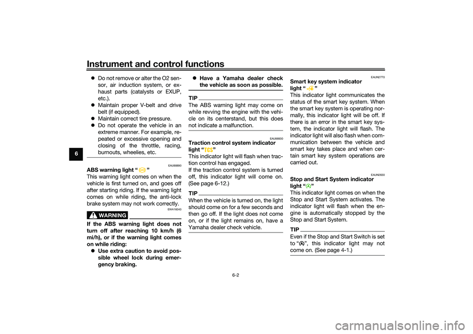
ABS warning light “ ”
This warning light comes on when the
vehicle is first turned on, and goes off
after starting riding. If the warning light
comes on while riding, the anti-lock
brake system may not work correctly.
WARNING
EWA16043
If the ABS warning light does not
turn off after reaching 10 km/h (6
mi/h), or if the warning light comes
on while riding:
Use extra caution to avoid pos-
sible wheel lock during emer-
gency braking. Have a Yamaha dealer check
the vehicle as soon as possible.
TIPThe ABS warning light may come on
while revving the engine with the vehi-
cle on its centerstand, but this does
not indicate a malfunction.
EAU88930
Traction control system indicator
light “ ”
This indicator light will flash when trac-
tion control has engaged.
If the traction control system is turned
off, this indicator light will come on.
(See page 6-12.)TIPWhen the vehicle is turned on, the light
should come on for a few seconds and
then go off. If the light does not come
on, or if the light remains on, have a
Yamaha dealer check vehicle.
EAUN2770
Smart key system indicator
light “ ”
This indicator light communicates the
status of the smart key system. When
the smart key system is operating nor-
mally, this indicator light will be off. If
there is an error in the smart key sys-
tem, the indicator light will flash. The
indicator light will also flash when com-
munication between the vehicle and
smart key takes place and when cer-
tain smart key system operations are
carried out.
EAUN2830
Stop and Start System indicator
light “ ”
This indicator light comes on when the
Stop and Start System activates. The
indicator light will flash when the en-
gine is automatically stopped by the
Stop and Start System.TIPEven if the Stop and Start Switch is set
to Ž, this indicator light may not
come on. (See page 4-1.)
A
UBALE0E0.book Page 2 Wednesday, September 30, 2020 1:37 PM
Page 37 of 114
Instrument and control functions
6-3
6
EAUN2781
Incoming call indicator light “ ”
This indicator light flashes when there
is an incoming call to the connected
smartphone. If you do not answer the
call, the indicator light stays on until
you turn the vehicle off.TIPThis function works only when the
smartphone is connected to the vehi-
cle.
EAUN2792
Incoming notification indicator
light “ ”
This indicator light flashes for 10 sec-
onds when the connected smartphone
receives an SNS, E-mail or other notifi-
cation. After that, the indicator light
stays on until you turn the vehicle off.TIPThis function works only when the
smartphone is connected to the
vehicle.
Notification setting is needed for
each application at the connected
smartphone in advance.
EAUN3040
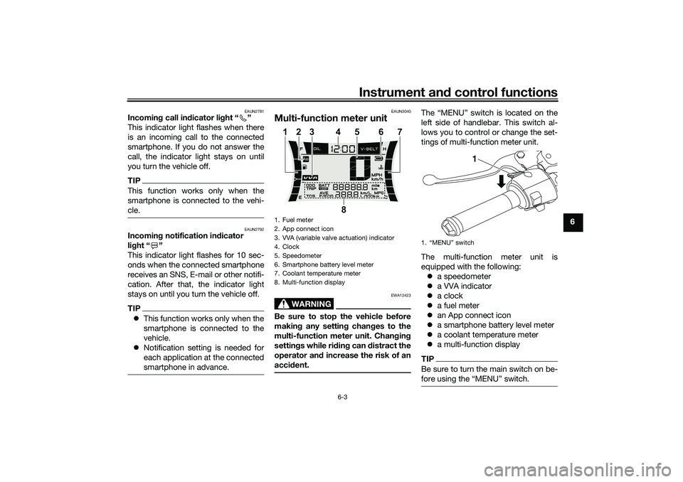
Multi-function meter unit
WARNING
EWA12423
Be sure to stop the vehicle before
making any setting changes to the
multi-function meter unit. Changing
settings while riding can distract the
operator and increase the risk of an
accident.
The “MENU” switch is located on the
left side of handlebar. This switch al-
lows you to control or change the set-
tings of multi-function meter unit.
The multi-function meter unit is
equipped with the following:
a speedometer
a VVA indicator
a clock
a fuel meter
an App connect icon
a smartphone battery level meter
a coolant temperature meter
a multi-function displayTIPBe sure to turn the main switch on be-
1. Fuel meter
2. App connect icon
3. VVA (variable valve actuation) indicator
4. Clock
5. Speedometer
6. Smartphone battery level meter
7. Coolant temperature meter
8. Multi-function display
8 1345 7
6 2
1.
1
UBALE0E0.book Page 3 Wednesday, September 30, 2020 1:37 PM
Page 38 of 114
Instrument and control functions
6-4
6
EAUN3051
App Connect icon
This icon comes on when CCU and
smartphone is connected via MyRide
App.TIPEven if the smartphone is not connect-
ed, when the vehicle is turned on, this
icon should come on for a few sec-
onds. Otherwise have a Yamaha dealer
check the CCU and the electrical cir-
cuit.
EAU86820
Switchin g the display units
The display units can be switched be-
tween kilometers and miles.
To switch the display units1. Turn the vehicle off.
2. While pushing the “MENU” switch, turn the vehicle on.
3. Continue to push the “MENU” switch until the display unit setting
screen comes on (approximately 5
seconds).
4. Push the “MENU” switch once to switch the display units. 5. Push the “MENU” switch for 1
second to confirm the setting.
EAU86831
Speed ometer
The speedometer shows the vehicle’s
traveling speed.
EAU86841
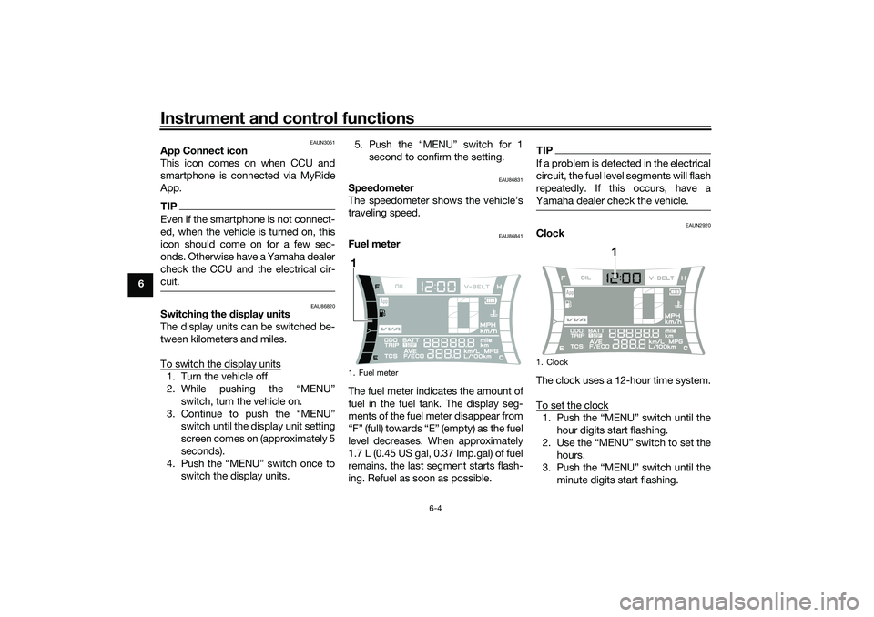
Fuel meter
The fuel meter indicates the amount of
fuel in the fuel tank. The display seg-
ments of the fuel meter disappear from
“F” (full) towards “E” (empty) as the fuel
level decreases. When approximately
1.7 L (0.45 US gal, 0.37 Imp.gal) of fuel
remains, the last segment starts flash-
ing. Refuel as soon as possible.
TIPIf a problem is detected in the electrical
circuit, the fuel level segments will flash
repeatedly. If this occurs, have a
Yamaha dealer check the vehicle.
EAUN2920
Clock
The clock uses a 12-hour time system.
To set the clock1. Push the “MENU” switch until the hour digits start flashing.
2. Use the “MENU” switch to set the hours.
3. Push the “MENU” switch until the minute digits start flashing.
1. Fuel meter1
1. Clock
1
UBALE0E0.book Page 4 Wednesday, September 30, 2020 1:37 PM
Page 39 of 114
Instrument and control functions
6-5
6 4. Use the “MENU” switch to set the
minutes.
5. Push the “MENU” switch until the
minute digits stop flashing. The
setting is confirmed.
TIPWhen CCU and smartphone is con-
nected after vehicle power on, the
clock is automatically adjusted.
EAU86860
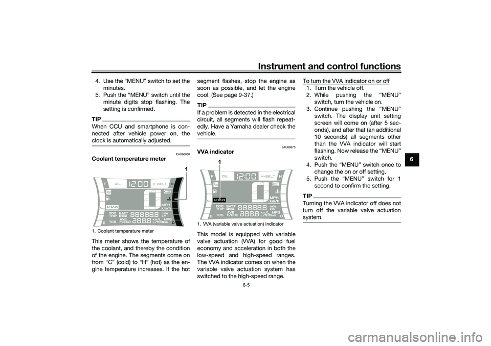
Coolant temperature meter
This meter shows the temperature of
the coolant, and thereby the condition
of the engine. The segments come on
from “C” (cold) to “H” (hot) as the en-
gine temperature increases. If the hotsegment flashes, stop the engine as
soon as possible, and let the engine
cool. (See page 9-37.)
TIPIf a problem is detected in the electrical
circuit, all segments will flash repeat-
edly. Have a Yamaha dealer check the
vehicle.
EAU86870
VVA indicator
This model is equipped with variable
valve actuation (VVA) for good fuel
economy and acceleration in both the
low-speed and high-speed ranges.
The VVA indicator comes on when the
variable valve actuation system has
switched to the high-speed range.To turn the VVA indicator on or off
1. Turn the vehicle off.
2. While pushing the “MENU”
switch, turn the vehicle on.
3. Continue pushing the “MENU”
switch. The display unit setting
screen will come on (after 5 sec-
onds), and after that (an additional
10 seconds) all segments other
than the VVA indicator will start
flashing. Now release the “MENU”
switch.
4. Push the “MENU” switch once to
change the on or off setting.
5. Push the “MENU” switch for 1
second to confirm the setting.TIPTurning the VVA indicator off does not
turn off the variable valve actuation
system.
1. Coolant temperature meter
1
1. VVA (variable valve actuation) indicator
1
UBALE0E0.book Page 5 Wednesday, September 30, 2020 1:37 PM
Page 40 of 114
Instrument and control functions
6-6
6
EAUN2800
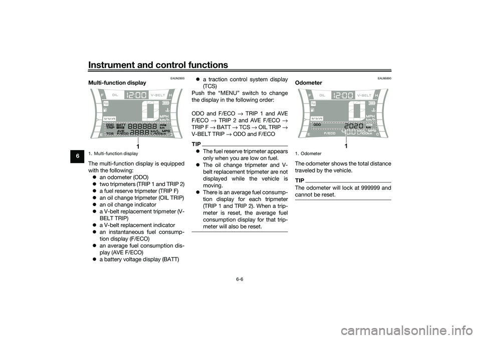
Multi-function display
The multi-function display is equipped
with the following:
an odometer (ODO)
two tripmeters (TRIP 1 and TRIP 2)
a fuel reserve tripmeter (TRIP F)
an oil change tripmeter (OIL TRIP)
an oil change indicator
a V-belt replacement tripmeter (V-
BELT TRIP)
a V-belt replacement indicator
an instantaneous fuel consump-
tion display (F/ECO)
an average fuel consumption dis-
play (AVE F/ECO)
a battery voltage display (BATT)a traction control system display
(TCS)
Push the “MENU” switch to change
the display in the following order:
ODO and F/ECO → TRIP 1 and AVE
F/ECO → TRIP 2 and AVE F/ECO →
TRIP F → BATT → TCS → OIL TRIP →
V-BELT TRIP → ODO and F/ECO
TIPThe fuel reserve tripmeter appears
only when you are low on fuel.
The oil change tripmeter and V-
belt replacement tripmeter are not
displayed while the vehicle is
moving.
There is an average fuel consump-
tion display for each tripmeter
(TRIP 1 and TRIP 2). When a trip-
meter is reset, the average fuel
consumption display for that trip-
meter will also be reset.
EAU86890
Odometer
The odometer shows the total distance
traveled by the vehicle.TIPThe odometer will lock at 999999 and
cannot be reset.
1. Multi-function display
1
1. Odometer
1
UBALE0E0.book Page 6 Wednesday, September 30, 2020 1:37 PM