warning YAMAHA NMAX 155 2021 Owner's Manual
[x] Cancel search | Manufacturer: YAMAHA, Model Year: 2021, Model line: NMAX 155, Model: YAMAHA NMAX 155 2021Pages: 114, PDF Size: 10.93 MB
Page 52 of 114

Instrument and control functions
6-18
6
NOTICE
ECA24020
Make sure that the keyhole cover is
installe d when the mechanical key is
not bein g use d.To close the seat
Push the rear of the seat down to lock
it in place.TIPMake sure that the seat is properly se-
cured before riding.
EAU37482
Helmet hold ersThe helmet holders are located under
the seat.
To secure a helmet to a helmet hol d-
er 1. Open the seat. (See page 6-17.)
2. Attach a helmet to a helmet hold- er, and then securely close the
seat. WARNING! Never ri de with
a helmet attached to the helmet
hol der, since the helmet may hit
o bjects, causin g loss of control
an d possi bly an acci dent.
[EWA10162]
To release a helmet from a helmet
hol der
Open the seat, remove the helmet from
the helmet holder, and then close the
seat.
1. Helmet holder
1
UBBDE0E0.book Page 18 Wednesday, June 2, 2021 2:57 PM
Page 54 of 114

Instrument and control functions
6-20
6
Since the stora ge compartment
may get wet while the vehicle is
b ein g washe d, wrap any articles
store d in the compartment in a
plastic bag .
Do not keep anythin g valua ble
or breakab le in the stora ge
compartment.
WARNING
EWA18950
Do not exceed the load limit of
1.5 k g (3.3 lb ) for stora ge com-
partment A.
Do not exceed the load limit of
0.3 k g (1 l b) for stora ge com-
partment B.
Do not exceed the load limit of
5.0 k g (11 l b) for the rear stora ge
compartment.
Do not exceed the maximum
loa d of 167 k g (368 lb ) for the ve-
hicle.
EAUN3020
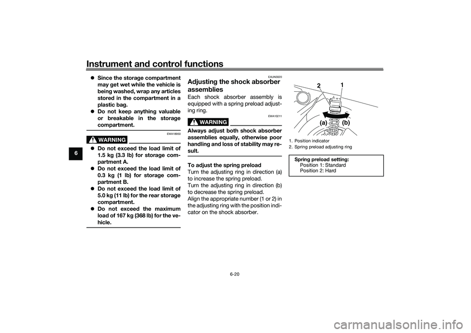
A djustin g the shock a bsorb er
assem bliesEach shock absorber assembly is
equipped with a spring preload adjust-
ing ring.
WARNING
EWA10211
Always a djust both shock ab sorber
assem blies equally, otherwise poor
han dlin g an d loss of sta bility may re-
sult.To a djust the sprin g preloa d
Turn the adjusting ring in direction (a)
to increase the spring preload.
Turn the adjusting ring in direction (b)
to decrease the spring preload.
Align the appropriate number (1 or 2) in
the adjusting ring with the position indi-
cator on the shock absorber.
1. Position indicator
2. Spring preload adjusting ringSprin g preloa d setting :
Position 1: Standard
Position 2: Hard
2 1
(a) (b)
UBBDE0E0.book Page 20 Wednesday, June 2, 2021 2:57 PM
Page 55 of 114

Instrument and control functions
6-21
6
EAUN2161
Power outlet This model is equipped with a 12V DC
power outlet.NOTICE
ECAN0140
Do not use the power outlet when
the en gine is off, an d d o not exceed
the specified electrical load ; other-
wise the fuse may blow or the b at-
tery may d ischarge.
When washin g the vehicle, do not di-
rect hi gh-pressure washers at the
power outlet area.
To use the power outlet 1. Turn the vehicle power off.
2. Remove the power outlet cap.
3. Turn the accessory off.
4. Insert the accessory plug into the power outlet.
5. Turn the vehicle power on and start the engine.
6. Turn the accessory on.TIPWhen finished riding, turn off the ac-
cessory and disconnect it from the
power outlet, and then install the cap.
WARNING
EWAN0050
To prevent electrical shock or short-
circuitin g, install the cap when the
power outlet is not in use.
1. Power outletMaximum electrical loa d:
12 W (1A)1
1. Power outlet cap1
UBBDE0E0.book Page 21 Wednesday, June 2, 2021 2:57 PM
Page 56 of 114

Instrument and control functions
6-22
6
EAU15306
Si destan dThe sidestand is located on the left
side of the frame. Raise the sidestand
or lower it with your foot while holding
the vehicle upright.TIPThe built-in sidestand switch is part of
the ignition circuit cut-off system,
which cuts the ignition in certain situa-
tions. (See the following section for an
explanation of the ignition circuit cut-
off system.)
WARNING
EWA10242
The vehicle must not be ri dden with
the si destan d d own, or if the si de-
stan d cannot b e properly move d up
(or does not stay up), otherwise the
si destan d coul d contact the groun d
an d d istract the operator, resultin g
in a possi ble loss of control.
Yamaha’s ig nition circuit cut-off
system has been desi gne d to assist
the operator in fulfillin g the respon-
si bility of raisin g the si destan d b e-
fore startin g off. Therefore, check this system reg
ularly and have a
Yamaha dealer repair it if it does not
function properly.
EAUT1098
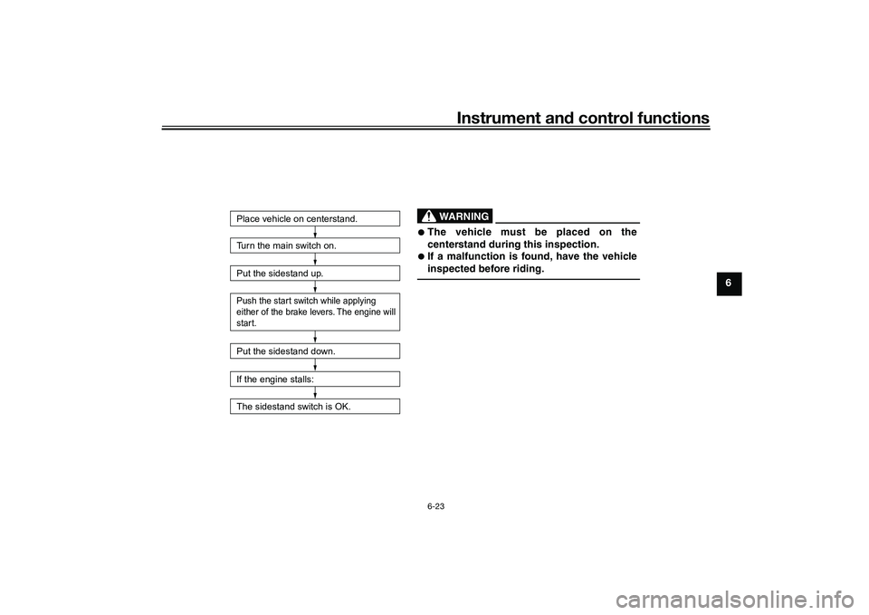
I g nition circuit cut-off systemCheck the operation of the sidestand
switch according to the following pro-
cedure.
UBBDE0E0.book Page 22 Wednesday, June 2, 2021 2:57 PM
Page 57 of 114

Instrument and control functions
6-23
6
Turn the main switch on.
Put the sidestand up.Push the start switch while applying
either of the brake levers. The engine will
start.Put the sidestand down.
If the engine stalls:
The sidestand switch is OK.Place vehicle on centerstand.
WARNING
The vehicle must be placed on the
centerstand during this inspection.
If a malfunction is found, have the vehicle
inspected before riding.
UBBDE0E0.book Page 23 Wednesday, June 2, 2021 2:57 PM
Page 58 of 114

For your safety – pre-operation checks
7-1
7
EAU1559B
Inspect your vehicle each time you use it to make sure the vehicle is in safe operating condition. Always follow the inspection
and maintenance procedures and schedules described in the Owner’s Manual.
WARNING
EWA11152
Failure to inspect or maintain the vehicle properly increases the possibility of an acci dent or equipment d amage.
Do not operate the vehicle if you fin d any pro blem. If a pro blem cannot be corrected b y the proce dures provi ded in
this manual, have the vehicle inspecte d b y a Yamaha dealer.Before using this vehicle, check the following points:
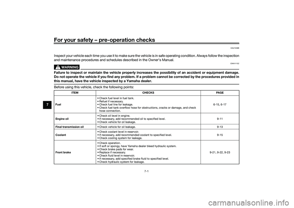
ITEM CHECKS PAGE
Fuel • Check fuel level in fuel tank.
• Refuel if necessary.
• Check fuel line for leakage.
• Check fuel tank overflow hose for obstructions, cracks or damage, and check
hose connection. 6-15, 6-17
En gine oil • Check oil level in engine.
• If necessary, add recommended oil to specified level.
• Check vehicle for oil leakage. 9-11
Final transmission oil • Check vehicle for oil leakage. 9-13
Coolant • Check coolant level in reservoir.
• If necessary, add recommended coolant to specified level.
• Check cooling system for leakage. 9-15
Front brake • Check operation.
• If soft or spongy, have Yamaha dealer bleed hydraulic system.
• Check brake pads for wear.
• Replace if necessary.
• Check fluid level in reservoir.
• If necessary, add specified brake fluid to specified level.
• Check hydraulic system for leakage. 9-21, 9-22, 9-23
UBBDE0E0.book Page 1 Wednesday, June 2, 2021 2:57 PM
Page 60 of 114

Operation and important rid ing points
8-1
8
EAU15952
Read the Owner’s Manual carefully to
become familiar with all controls. If
there is a control or function you do not
understand, ask your Yamaha dealer.
WARNING
EWA10272
Failure to familiarize yourself with
the controls can lead to loss of con-
trol, which coul d cause an acci dent
or injury.
EAU16842
En gine break-inThere is never a more important period
in the life of your engine than the period
between 0 and 1600 km (1000 mi). For
this reason, you should read the fol-
lowing material carefully.
Since the engine is brand new, do not
put an excessive load on it for the first
1600 km (1000 mi). The various parts in
the engine wear and polish themselves
to the correct operating clearances.
During this period, prolonged full-throt-
tle operation or any condition that
might result in engine overheating
must be avoided.
EAUM2012
0–1000 km (0–600 mi)
Avoid prolonged operation above 1/3
throttle. NOTICE: After 1000 km (600
mi) of operation, be sure to replace
the en gine oil an d final transmission
oil.
[ECA11662]
1000–1600 km (600–1000 mi)
Avoid prolonged operation above 1/2
throttle. 1600 km (1000 mi) an
d b eyon d
The vehicle can now be operated nor-
mally.
NOTICE
ECA10271
If any en gine trou ble shoul d occur
d urin g the en gine break-in perio d,
imme diately have a Yamaha dealer
check the vehicle.
UBBDE0E0.book Page 1 Wednesday, June 2, 2021 2:57 PM
Page 61 of 114

Operation and important ri din g points
8-2
8
EAU86741
Startin g the en gineThe ignition circuit cut-off system will
enable starting only when the side-
stand is up.
To start the engine1. Turn the main switch on.
2. Confirm the indicator and warning light(s) come on for a few sec-
onds, and then go off. (See page
6-1.)TIPDo not start the engine if the en-
gine trouble warning light remains
on.
The ABS warning light should
come on and stay on until the ve-
hicle reaches a speed of 10 km/h
(6 mi/h).NOTICE
ECA24110
If a warnin g or in dicator li ght does
not work as d escribed a bove, have a
Yamaha dealer check the vehicle.3. Close the throttle completely.
4. While applying the front or rear
brake, push the start switch. 5. Release the start switch when the
engine starts, or after 5 seconds.
Wait 10 seconds before pressing
the switch again to allow battery
voltage to restore.
NOTICE
ECA11043
For maximum en gine life, never ac-
celerate har d when the en gine is
col d!
EAU45093
Startin g off1. While pulling the rear brake lever
with your left hand and holding the
grab bar with your right hand,
push the scooter off the center-
stand.
2. Sit astride the seat, and then ad- just the rear view mirrors.
3. Switch the turn signals on.
4. Check for oncoming traffic, and then slowly turn the throttle grip
(on the right) in order to take off.
5. Switch the turn signals off.1. Grab bar
1
UBBDE0E0.book Page 2 Wednesday, June 2, 2021 2:57 PM
Page 62 of 114

Operation and important rid ing points
8-3
8
EAU16782
Acceleration an d d ecelerationThe speed can be adjusted by opening
and closing the throttle. To increase
the speed, turn the throttle grip in di-
rection (a). To reduce the speed, turn
the throttle grip in direction (b).
EAU60650
Brakin g
WARNING
EWA17790
Avoi d b rakin g har d or su ddenly
(especially when leanin g over to
one si de), otherwise the vehicle
may skid or overturn.
Railroa d crossin gs, streetcar
rails, iron plates on road con-
struction sites, an d manhole
covers become extremely slip-
pery when wet. Therefore, slow
d own when approachin g such
areas an d cross them with cau-
tion.
Keep in min d that b raking on a
wet road is much more difficult.
Ride slowly d own a hill, as brak-
in g d ownhill can be very d iffi-
cult.1. Close the throttle completely.
2. Apply both front and rear brakes simultaneously while gradually in-
creasing the pressure.
EAU16821
Tips for re ducin g fuel con-
sumptionFuel consumption depends largely on
your riding style. Consider the follow-
ing tips to reduce fuel consumption:
Avoid high engine speeds during
acceleration.
Avoid high engine speeds with no
load on the engine.
Turn the engine off instead of let-
ting it idle for an extended length
of time (e.g., in traffic jams, at traf-
fic lights or at railroad crossings).
(b)
(a)
ZAUM0199
UBBDE0E0.book Page 3 Wednesday, June 2, 2021 2:57 PM
Page 63 of 114

Operation and important ri din g points
8-4
8
EAUW4891
Parkin g When parking, turn off the Stop and
Start System and then stop the engine.
After turning off the main switch, be
sure to turn off the smart key and take
it with you.
WARNING
EWA18840
Since the en gine an d exhaust
system can b ecome very hot,
park in a place where pe destri-
ans or chil dren are not likely to
touch them an d b e burne d.
Do not park on a slope or on soft
groun d, otherwise the vehicle
may overturn, increasin g the
risk of a fuel leak an d fire.
Do not park near grass or other
flamma ble materials which
mi ght catch fire.
If the Stop an d Start System is
left turne d on, the b attery could
b ecome dischar ged an d it may
not be possi ble to restart the
en gine due to insufficient b at-
tery volta ge.
TIPEven when the vehicle is parked in a lo-
cation partitioned by a fence or the
glass window of a shop, if the smart
key is within operating range, other
people will be able to start the engine
and operate the vehicle. Please turn
the smart key off when leaving the ve-
hicle. (See page 3-8.)
UBBDE0E0.book Page 4 Wednesday, June 2, 2021 2:57 PM