YAMAHA TDM 900 2003 Owners Manual
Manufacturer: YAMAHA, Model Year: 2003, Model line: TDM 900, Model: YAMAHA TDM 900 2003Pages: 110, PDF Size: 7.38 MB
Page 101 of 110

8
8-3
SPECIFICATIONS
Maximum load* 203 kg
Tire air pressure
(measured on cold tires)
Up to 90 kg*
Front
225 kPa (2.25 kgf/cm2, 2.25 bar)
Rear250 kPa (2.50 kgf/cm2, 2.50 bar)
90 kg load–Maximum*
Front
225 kPa (2.25 kgf/cm2, 2.25 bar)
Rear290 kPa (2.90 kgf/cm2, 2.90 bar)
High-speed riding
Front
225 kPa (2.25 kgf/cm2, 2.25 bar)
Rear250 kPa (2.50 kgf/cm2, 2.50 bar)
*Total weight of rider, passenger, cargo and accessories
Wheels
Front
Type Cast wheel
Size 18 M/C ×MT 3.50
Rear
Type Cast wheel
Size 17 M/C ×MT 5.00Brakes
Front
Type Dual disc brake
Operation Right hand
Fluid DOT 4
Rear
Type Single disc brake
Operation Right foot
Fluid DOT 4
Suspension
Front
Type Telescopic fork
Rear
Type Swingarm (link suspension)
Spring/shock absorber
Front Coil spring/oil damper
Rear Coil spring/gas-oil damper
Wheel travel
Front 150 mm
Rear 133 mm
5PS-28199-E1 8/29/02 9:17 AM Page 100
Page 102 of 110

8
8-4
SPECIFICATIONS
Electrical system
Ignition system T.C.I. (digital)
Charging system
Type A.C. magneto
Standard output 14 V, 31.5 A @ 5,000 r/min
Battery
Type GT12B-4
Voltage, capacity 12 V, 10 Ah
Headlight bulb typeHalogen
Bulb voltage, wattage ×quantity
Headlight 12 V, 55 W ×2
Auxiliary light 12 V, 5 W ×1
Tail/brake light 12 V, 5/21 W ×1
Front turn signal light 12 V, 10 W ×2
Rear turn signal light 12 V, 10 W ×2
Meter lighting 12 V, 2 W ×2
Neutral indicator light 12 V, 1.2 W ×1
High beam indicator light 12 V, 1.4 W ×1
Turn signal indicator light 12 V, 1.2 W ×2
Oil level warning light L.E.D. ×1
Engine trouble warning light 12 V, 1.4 W ×1Fuses
Main fuse 40 A
Headlight fuse 15 A
Signaling system fuse 10 A
Ignition fuse 10 A
Turn signal light and hazard
fuse 10 A
Odometer and clock fuse
(backup fuse) 5 A
Radiator fan fuse 20 A
Electronic fuel injection
system fuse 10 A
5PS-28199-E1 8/29/02 9:17 AM Page 101
Page 103 of 110

8
8-5
SPECIFICATIONS
EAU04513
Conversion tableConversion table
All specification data in this manual are listed in SI and
METRIC UNITS.
Use this table to convert METRIC unit values to IMPERIAL
unit values.
Example:
METRIC VALUE CONVERSION
FACTORIMPERIAL VALUE
2 mm× 0.03937 = 0.08 in
Conversion table
METRIC SYSTEM TO IMPERIAL SYSTEM
Metric unit Conversion factor Imperial unit
Torquem·kgf
m·kgf
cm·kgf
cm·kgf
× 7.233× 86.794× 0.0723× 0.8679ft·lbf
in·lbf
ft·lbf
in·lbf
Weightkg
g
× 2.205× 0.03527lb
oz
Speed km/h
× 0.6214 mi/h
Distancekm
m
m
cm
mm
× 0.6214× 3.281× 1.094× 0.3937× 0.03937mi
ft
yd
in
in
Volume,
Capacitycc (cm3)
cc (cm3)
L (liter)
L (liter)× 0.03527× 0.06102× 0.8799× 0.2199oz (IMP liq.)
cu·in
qt (IMP liq.)
gal (IMP liq.)
Miscellaneouskg/mm
kgf/cm
2
°C
× 55.997× 14.2234× 1.8 + 32 lb/in
psi (lbf/in
2)
°F
5PS-28199-E1 8/29/02 9:17 AM Page 102
Page 104 of 110

CONSUMER INFORMATION
Identification numbers .......................................................................9-1
Key identification number ..................................................................9-1
Vehicle identification number .............................................................9-1
Model label ........................................................................................9-2
9
5PS-28199-E1 8/29/02 9:17 AM Page 103
Page 105 of 110

9
9-1
EAU01039
CONSUMER INFORMATION
EAU02944
Identification numbersIdentification numbersRecord the key identification number,
vehicle identification number and
model label information in the spaces
provided below for assistance when
ordering spare parts from a Yamaha
dealer or for reference in case the
vehicle is stolen.
1. KEY IDENTIFICATION
NUMBER:
2. VEHICLE IDENTIFICATION
NUMBER:
3. MODEL LABEL INFORMATION:
EAU01043
Vehicle identification numberVehicle identification numberThe vehicle identification number is
stamped into the steering head pipe.
Record this number in the space pro-
vided.
NOTE:
The vehicle identification number is
used to identify your motorcycle and
may be used to register your motor-
cycle with the licensing authority in
your area.
1. Identification number
EAU01041
Key identification numberKey identification numberThe key identification number is
stamped into the key tag.
Record this number in the space pro-
vided and use it for reference when
ordering a new key.
1. Key identification number
1
6
5PS-28199-E1 8/29/02 9:17 AM Page 104
Page 106 of 110

9
9-2
CONSUMER INFORMATION
EAU01050
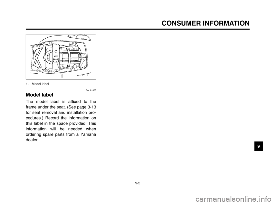
Model labelModel labelThe model label is affixed to the
frame under the seat. (See page 3-13
for seat removal and installation pro-
cedures.) Record the information on
this label in the space provided. This
information will be needed when
ordering spare parts from a Yamaha
dealer.
1. Model label
5PS-28199-E1 8/29/02 9:17 AM Page 105
Page 107 of 110

INDEX
Checking ............................................6-27
Drive chain, lubricating .........................6-28
E
Engine break-in ......................................5-3
Engine idling speed ..............................6-17
Engine oil and oil filter element ..............6-8
F
Front and rear brake pads, checking ....6-24
Front fork, adjusting ..............................3-14
Front fork, checking ..............................6-31
Fuel ......................................................3-11
Fuel consumption, tips for reducing .......5-3
Fuel tank breather hose .......................3-12
Fuel tank cap ........................................3-10
Fuses, replacing ...................................6-34
H
Handlebar switches ................................3-7
Dimmer switch .....................................3-7
Engine stop switch ...............................3-8
Hazard switch ......................................3-8
Horn switch ..........................................3-8
Pass switch ..........................................3-7
Start switch ..........................................3-8
Turn signal switch ................................3-8
Headlight bulb, replacing ......................6-35
I
Identification numbers ............................9-1
Ignition circuit cut-off system ................3-19Indicator and warning lights ....................3-2
Fuel level warning symbol ...................3-2
Turn signal indicator lights ...................3-3
High beam indicator light .....................3-3
Neutral indicator light ...........................3-3
Engine trouble warning light ................3-3
Oil level warning light ...........................3-3
K
Key identification number .......................9-1
L
Luggage strap holders ..........................3-18
M
Main switch/steering lock .......................3-1
Model label .............................................9-2
P
Parking ...................................................5-4
Part locations ..........................................2-1
Periodic maintenance and lubrication
chart .....................................................6-2
Pre-operation check list ..........................4-1
R
Rear brake light switch, adjusting .........6-24
Rear suspension, lubricating ................6-31
S
Seat ......................................................3-13
Shift pedal ..............................................3-9A
Air filter element, replacing ...................6-16
Anti-theft alarm (optional) .......................3-7
B
Battery ..................................................6-33
Brake and clutch levers, checking
and lubricating ...................................6-30
Brake and shift pedals, checking
and lubricating ...................................6-30
Brake fluid level, checking ....................6-25
Brake fluid, changing ............................6-26
Brake lever .............................................3-9
Brake pedal ..........................................3-10
Brake pedal position, adjusting ............6-23
C
Cables, checking and lubricating ..........6-29
Care ........................................................7-1
Catalytic converter ................................3-12
Clutch lever ............................................3-9
Clutch lever free play, adjusting ...........6-22
Conversion table ....................................8-5
Coolant .................................................6-11
Checking ............................................6-11
Changing ...........................................6-13
Coolant temperature gauge ....................3-6
Cowlings and panels, removing
and installing ........................................6-5
D
Drive chain slack ..................................6-27
Adjusting ............................................6-27
5PS-28199-E1 8/29/02 9:17 AM Page 106
Page 108 of 110

Shift points (for Switzerland only) ...........5-3
Shifting ...................................................5-2
Shock absorber assembly, adjusting ....3-16
Sidestand .............................................3-18
Sidestand, checking and lubricating .....6-30
Spark plugs, checking ............................6-7
Specifications .........................................8-1
Speedometer unit ...................................3-4
Starting the engine .................................5-1
Steering, checking ................................6-32
Storage ...................................................7-4
Storage compartment ...........................3-14
Supporting the motorcycle ....................6-38
T
Tachometer unit .....................................3-5
Tail/brake light bulb, replacing ..............6-37
Throttle cable free play, adjusting ........6-18
Throttle grip and cable, checking
and lubricating ...................................6-29
Tires .....................................................6-18
Tool kit ....................................................6-1
Troubleshooting ....................................6-43
Troubleshooting charts .........................6-44
Turn signal light bulb, replacing ............6-37
V
Valve clearance, adjusting ...................6-18
Vehicle identification number .................9-1W
Wheel (front)..........................................6-39
Installing .............................................6-40
Removing ...........................................6-39
Wheel (rear) .........................................6-40
Installing .............................................6-42
Removing ...........................................6-40
Wheel bearings, checking ....................6-32
Wheels .................................................6-22
INDEX
5PS-28199-E1 8/29/02 9:17 AM Page 107
Page 109 of 110

5PS-28199-E1 8/29/02 9:17 AM Page 108
Page 110 of 110

PRINTED ON RECYCLED PAPER
YAMAHA MOTOR CO., LTD.
PRINTED IN JAPAN
2002.9-0.5x1 !
(E)
OWNER’S MANUAL
5PS-28199-E1
TDM900
5PS-E1_hyoushi 8/29/02 8:44 AM Page 1