check engine light YAMAHA TMAX 2002 Owners Manual
[x] Cancel search | Manufacturer: YAMAHA, Model Year: 2002, Model line: TMAX, Model: YAMAHA TMAX 2002Pages: 102, PDF Size: 1.67 MB
Page 18 of 102
3-2
INSTRUMENT AND CONTROL FUNCTIONS
3
EAU00056
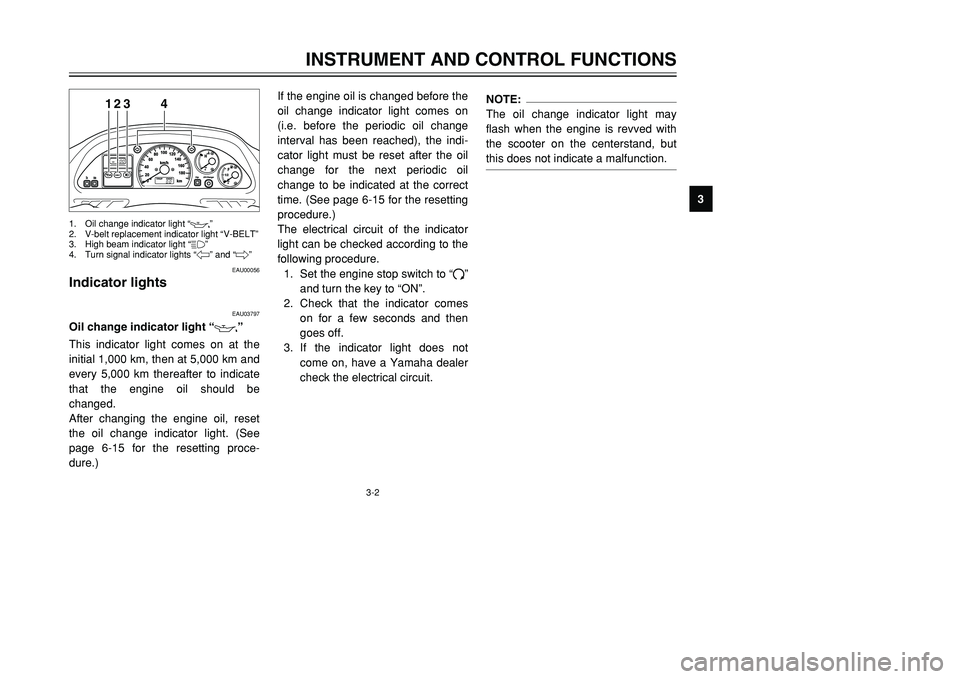
Indicator lightsIndicator lights
EAU03797
Oil change indicator light “
7
”
Oil change indicator lightThis indicator light comes on at the
initial 1,000 km, then at 5,000 km and
every 5,000 km thereafter to indicate
that the engine oil should be
changed.
After changing the engine oil, reset
the oil change indicator light. (See
page 6-15 for the resetting proce-
dure.)If the engine oil is changed before the
oil change indicator light comes on
(i.e. before the periodic oil change
interval has been reached), the indi-
cator light must be reset after the oil
change for the next periodic oil
change to be indicated at the correct
time. (See page 6-15 for the resetting
procedure.)
The electrical circuit of the indicator
light can be checked according to the
following procedure.
1. Set the engine stop switch to “#”
and turn the key to “ON”.
2. Check that the indicator comes
on for a few seconds and then
goes off.
3. If the indicator light does not
come on, have a Yamaha dealer
check the electrical circuit.
NOTE:
The oil change indicator light may
flash when the engine is revved with
the scooter on the centerstand, but
this does not indicate a malfunction.
123
4
1. Oil change indicator light “
7
”
2. V-belt replacement indicator light “V-BELT”
3. High beam indicator light “&”
4. Turn signal indicator lights “4” and “6”
5GJ-9-E1 9/4/01 1:27 PM Page 17
Page 19 of 102
3-3
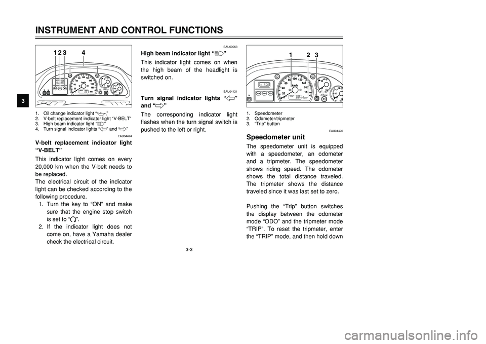
EAU04424
V-belt replacement indicator light
“V-BELT”V-belt replacement indicator lightThis indicator light comes on every
20,000 km when the V-belt needs to
be replaced.
The electrical circuit of the indicator
light can be checked according to the
following procedure.
1. Turn the key to “ON” and make
sure that the engine stop switch
is set to “#”.
2. If the indicator light does not
come on, have a Yamaha dealer
check the electrical circuit.
EAU00063
High beam indicator light “&”High beam indicator lightThis indicator light comes on when
the high beam of the headlight is
switched on.
EAU04121
Turn signal indicator lights “4”
and “6”Turn signal indicator lightsThe corresponding indicator light
flashes when the turn signal switch is
pushed to the left or right.
INSTRUMENT AND CONTROL FUNCTIONS
3
123
4
1. Oil change indicator light “
7
”
2. V-belt replacement indicator light “V-BELT”
3. High beam indicator light “&”
4. Turn signal indicator lights “4” and “6”
EAU04426
Speedometer unitSpeedometer unitThe speedometer unit is equipped
with a speedometer, an odometer
and a tripmeter. The speedometer
shows riding speed. The odometer
shows the total distance traveled.
The tripmeter shows the distance
traveled since it was last set to zero.
Pushing the “Trip” button switches
the display between the odometer
mode “ODO” and the tripmeter mode
“TRIP”. To reset the tripmeter, enter
the “TRIP” mode, and then hold down
123
1. Speedometer
2. Odometer/tripmeter
3.“Trip” button
5GJ-9-E1 9/4/01 1:27 PM Page 18
Page 21 of 102
3-5
EAU04402
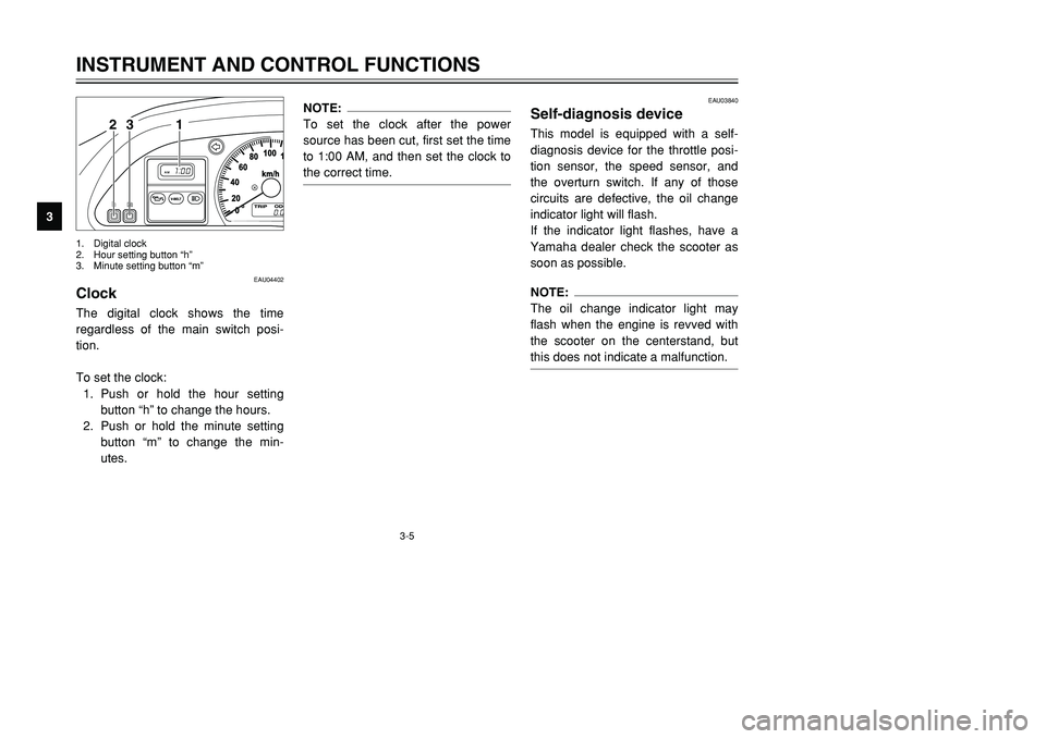
ClockClockThe digital clock shows the time
regardless of the main switch posi-
tion.
To set the clock:
1. Push or hold the hour setting
button “h” to change the hours.
2. Push or hold the minute setting
button “m” to change the min-
utes.
NOTE:
To set the clock after the power
source has been cut, first set the time
to 1:00 AM, and then set the clock to
the correct time.
EAU03840
Self-diagnosis deviceSelf-diagnosis deviceThis model is equipped with a self-
diagnosis device for the throttle posi-
tion sensor, the speed sensor, and
the overturn switch. If any of those
circuits are defective, the oil change
indicator light will flash.
If the indicator light flashes, have a
Yamaha dealer check the scooter as
soon as possible.NOTE:
The oil change indicator light may
flash when the engine is revved with
the scooter on the centerstand, but
this does not indicate a malfunction.
INSTRUMENT AND CONTROL FUNCTIONS
3
1 23
1. Digital clock
2. Hour setting button “h”
3. Minute setting button “m”
5GJ-9-E1 9/4/01 1:27 PM Page 20
Page 31 of 102
3-15
EW000044
wThe scooter must not be ridden
with the sidestand down, or if the
sidestand cannot be properly
moved up (or does not stay up),
otherwise the sidestand could con-
tact the ground and distract the
operator, resulting in a possible
loss of control. Yamaha’s ignition
circuit cut-off system has been
designed to assist the operator in
fulfilling the responsibility of rais-
ing the sidestand before starting
off. Therefore, check this system
regularly as described below and
have a Yamaha dealer repair it if it
does not function properly.
EAU00337
Ignition circuit cut-off
systemIgnition circuit cut-off systemThe ignition circuit cut-off system
(comprising the sidestand switch and
brake light switches) has the follow-
ing functions.
8It prevents starting when the
sidestand is up, but neither brake
is applied.
8It prevents starting when either
brake is applied, but the side-
stand is still down.
8It cuts the running engine when
the sidestand is moved down.
Periodically check the operation of
the ignition circuit cut-off system
according to the following procedure.
EW000045
wIf a malfunction is noted, have a
Yamaha dealer check the system
before riding.
INSTRUMENT AND CONTROL FUNCTIONS
3 5GJ-9-E1 9/4/01 1:27 PM Page 30
Page 44 of 102
PERIODIC MAINTENANCE AND MINOR REPAIR
Owner’s tool kit ..................................................... 6-1
Periodic maintenance and lubrication chart .......... 6-3
Removing and installing cowlings and panels ...... 6-6
Checking the spark plugs ..................................... 6-9
Engine oil and oil filter cartridge .......................... 6-12
Chain drive oil ..................................................... 6-15
Coolant ............................................................... 6-17
Cleaning the air filter element ............................. 6-19
Adjusting the carburetors .................................... 6-21
Adjusting the engine idling speed ....................... 6-21
Adjusting the throttle cable free play ................... 6-22
Adjusting the valve clearance ............................. 6-22
Tires .................................................................... 6-23
Cast wheels ........................................................ 6-25
Front and rear brake levers ................................ 6-25
Checking the front and rear brake pads ............. 6-26
Checking the brake fluid level ............................. 6-27
Changing the brake fluid ..................................... 6-28
Checking and lubricating the throttle grip
and cable .......................................................... 6-29
Lubricating the front and rear brake levers ......... 6-29
Checking and lubricating the centerstand and
sidestand .......................................................... 6-29
Checking the front fork ........................................ 6-30Checking the steering ......................................... 6-31
Checking the wheel bearings .............................. 6-31
Battery ................................................................ 6-32
Replacing the fuses ............................................ 6-34
Replacing a headlight bulb ................................. 6-35
Troubleshooting .................................................. 6-36
Troubleshooting charts ....................................... 6-37
6
5GJ-9-E1 9/4/01 1:27 PM Page 43
Page 49 of 102
6-5
PERIODIC MAINTENANCE AND MINOR REPAIR
6
EAU03884
NOTE:
8The air filter needs more frequent service if you are riding in unusually wet or dusty areas.
8Hydraulic brake service
9Regularly check and, if necessary, correct the brake fluid level.
9Every two years replace the internal components of the brake master cylinders and calipers, and change the
brake fluid.
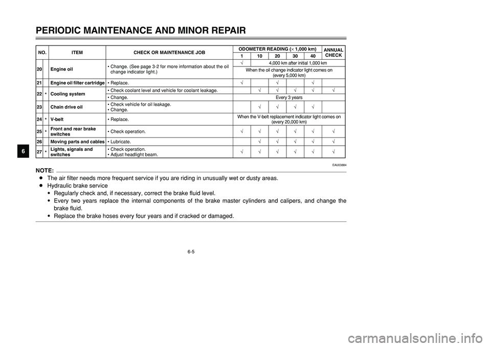
9Replace the brake hoses every four years and if cracked or damaged.20 Engine oil•Change. (See page 3-2 for more information about the oil
change indicator light.)√4,000 km after initial 1,000 km
When the oil change indicator light comes on
(every 5,000 km)
21 Engine oil filter cartridge•Replace.√√√
22
*Cooling system•Check coolant level and vehicle for coolant leakage.√√√√ √
•Change.Every 3 years
23 Chain drive oil•Check vehicle for oil leakage.
•Change.√√√√
24*V-belt•Replace.When the V-belt replacement indicator light comes on
(every 20,000 km)
25*Front and rear brake
switches•Check operation.√√√√√ √
26 Moving parts and cables•Lubricate.√√√√ √
27*Lights, signals and
switches•Check operation.
•Adjust headlight beam.√√√√√ √ NO. ITEM CHECK OR MAINTENANCE JOBODOMETER READING (× 1,000 km)
ANNUAL
CHECK
1 10203040
5GJ-9-E1 9/4/01 1:27 PM Page 48
Page 55 of 102

6-11
PERIODIC MAINTENANCE AND MINOR REPAIR
6To check the spark plugs
1. Check that the porcelain insula-
tor around the center electrode
on each spark plug is a medium-
to-light tan (the ideal color when
the scooter is ridden normally).
2. Check that all spark plugs
installed in the engine have the
same color.
NOTE:
If any spark plug shows a distinctly
different color, the engine could be
defective. Do not attempt to diagnose
such problems yourself. Instead,
have a Yamaha dealer check the
scooter.3. Check each spark plug for elec-
trode erosion and excessive car-
bon or other deposits, and
replace it if necessary.
NOTE:
If a torque wrench is not available
when installing a spark plug, a good
estimate of the correct torque is
1/4–1/2 turn past finger tight.
However, the spark plug should be
tightened to the specified torque as
soon as possible.4. Install the spark plug cap. To install a spark plug
1. Measure the spark plug gap with
a wire thickness gauge and, if
necessary, adjust the gap to
specification.
2. Clean the surface of the spark
plug gasket and its mating sur-
face, and then wipe off any grime
from the spark plug threads.
3. Install the spark plug with the
spark plug wrench, and then
tighten it to the specified torque.
a
a. Spark plug gap
Specified spark plug:
CR7E (NGK)
Spark plug gap:
0.7–0.8 mm
Tightening torque:
Spark plug:
12.5 Nm (1.25 m·kgf)
5GJ-9-E1 9/4/01 1:27 PM Page 54
Page 56 of 102
6-12
PERIODIC MAINTENANCE AND MINOR REPAIR
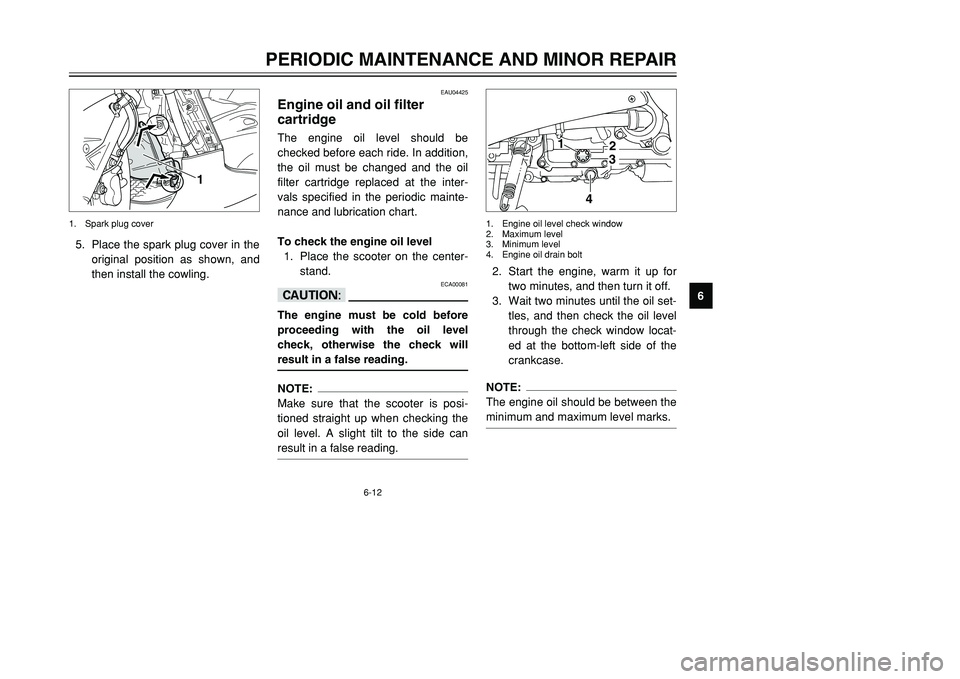
6 5. Place the spark plug cover in the
original position as shown, and
then install the cowling.
1
1. Spark plug cover
2. Start the engine, warm it up for
two minutes, and then turn it off.
3. Wait two minutes until the oil set-
tles, and then check the oil level
through the check window locat-
ed at the bottom-left side of the
crankcase.NOTE:
The engine oil should be between the
minimum and maximum level marks.
32
1
4
1. Engine oil level check window
2. Maximum level
3. Minimum level
4. Engine oil drain bolt
EAU04425
Engine oil and oil filter
cartridgeEngine oil and oil filter cartridgeThe engine oil level should be
checked before each ride. In addition,
the oil must be changed and the oil
filter cartridge replaced at the inter-
vals specified in the periodic mainte-
nance and lubrication chart.
To check the engine oil level
1. Place the scooter on the center-
stand.
ECA00081
cCThe engine must be cold before
proceeding with the oil level
check, otherwise the check will
result in a false reading.NOTE:
Make sure that the scooter is posi-
tioned straight up when checking the
oil level. A slight tilt to the side can
result in a false reading.
5GJ-9-E1 9/4/01 1:27 PM Page 55
Page 61 of 102
6-17
PERIODIC MAINTENANCE AND MINOR REPAIR
6
EAU03850
CoolantCoolantTo check the coolant level
1. Place the scooter on a level sur-
face and hold it in an upright
position.NOTE:
8The coolant level must be
checked on a cold engine since
the level varies with engine tem-
perature.
8Make sure that the scooter is
positioned straight up when
checking the coolant level. A
slight tilt to the side can result in
a false reading.
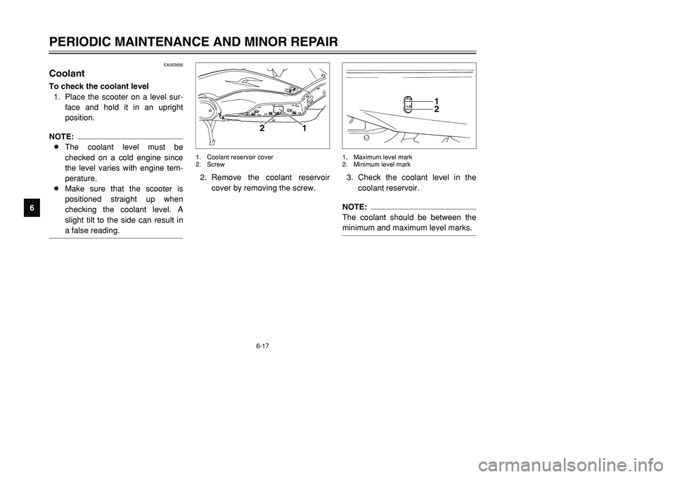
3. Check the coolant level in the
coolant reservoir.NOTE:
The coolant should be between the
minimum and maximum level marks.
12
1. Maximum level mark
2. Minimum level mark
2. Remove the coolant reservoir
cover by removing the screw.
1
2
1. Coolant reservoir cover
2. Screw
5GJ-9-E1 9/4/01 1:27 PM Page 60
Page 99 of 102
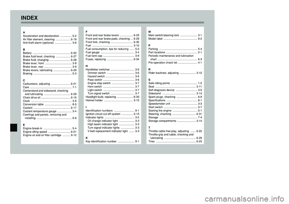
INDEX
F
Front and rear brake levers ................. 6-25
Front and rear brake pads, checking ... 6-26
Front fork, checking ............................. 6-30
Fuel ..................................................... 3-10
Fuel consumption, tips for reducing ...... 5-3
Fuel gauge ............................................ 3-4
Fuel tank cap ......................................... 3-9
Fuses, replacing .................................. 6-34
H
Handlebar switches ............................... 3-6
Dimmer switch .................................... 3-6
Hazard switch ...................................... 3-6
Pass switch ......................................... 3-6
Engine stop switch .............................. 3-7
Horn switch ......................................... 3-7
Light switch ......................................... 3-7
Turn signal switch ............................... 3-7
Headlight bulb, replacing ..................... 6-35
Helmet holder ...................................... 3-13
I
Identification numbers ........................... 9-1
Ignition circuit cut-off system ............... 3-15
Indicator lights ....................................... 3-2
Oil change indicator light .................... 3-2
High beam indicator light .................... 3-3
Turn signal indicator lights .................. 3-3
V-belt replacement indicator light ....... 3-3
K
Key identification number ...................... 9-1
M
Main switch/steering lock ...................... 3-1
Model label ............................................ 9-2
P
Parking .................................................. 5-4
Part locations ......................................... 2-1
Periodic maintenance and lubrication
chart .................................................... 6-3
Pre-operation check list ......................... 4-1
R
Rider backrest, adjusting ..................... 3-12
S
Safe-riding points .................................. 1-2
Seat ..................................................... 3-11
Self-diagnosis device ............................ 3-5
Sidestand ............................................ 3-14
Spark plugs, checking ........................... 6-9
Specifications ........................................ 8-1
Speedometer unit .................................. 3-3
Start switch ............................................ 3-7
Starting the engine ................................ 5-1
Steering, checking ............................... 6-31
Storage .................................................. 7-4
Storage compartments ........................ 3-14
T
Throttle cable free play, adjusting ....... 6-22
Throttle grip and cable, checking and
lubricating ......................................... 6-29
Tires .................................................... 6-23
A
Acceleration and deceleration ............... 5-2
Air filter element, cleaning ................... 6-19
Anti-theft alarm (optional) ...................... 3-6
B
Battery ................................................. 6-32
Brake fluid level, checking ................... 6-27
Brake fluid, changing ........................... 6-28
Brake lever, front ................................... 3-9
Brake lever, rear .................................... 3-9
Brake levers, lubricating ...................... 6-29
Braking .................................................. 5-3
C
Carburetors, adjusting ......................... 6-21
Care ....................................................... 7-1
Centerstand and sidestand, checking
and lubricating .................................. 6-29
Chain drive oil ...................................... 6-15
Clock ..................................................... 3-5
Conversion table ................................... 8-5
Coolant ................................................ 6-17
Coolant temperature gauge ................... 3-4
Cowlings and panels, removing and
installing .............................................. 6-6
E
Engine break-in ..................................... 5-4
Engine idling speed ............................. 6-21
Engine oil and oil filter cartridge .......... 6-12
5GJ-9-E1 9/4/01 1:27 PM Page 98