clock YAMAHA TMAX 2002 Owners Manual
[x] Cancel search | Manufacturer: YAMAHA, Model Year: 2002, Model line: TMAX, Model: YAMAHA TMAX 2002Pages: 102, PDF Size: 1.67 MB
Page 15 of 102

2-3
DESCRIPTION
2
1. Rear brake lever (page 3-9)
2. Left handlebar switches (page 3-6)
3. Clock (page 3-5)
4. Speedometer unit (page 3-3)
5. Coolant temperature gauge (page 3-4)6. Fuel gauge (page 3-4)
7. Right handlebar switches (page 3-7)
8. Front brake lever (page 3-9)
9. Throttle grip (page 6-22, 6-29)
10. Main switch/steering lock (page 3-1)
4
3
2
5
6
7
8
1
109
Controls and instruments
5GJ-9-E1 9/4/01 1:27 PM Page 14
Page 16 of 102

INSTRUMENT AND CONTROL FUNCTIONSMain switch/steering lock .................................................................. 3-1
Indicator lights .................................................................................. 3-2
Speedometer unit ............................................................................. 3-3
Fuel gauge ........................................................................................ 3-4
Coolant temperature gauge .............................................................. 3-4
Clock ................................................................................................. 3-5
Self-diagnosis device ........................................................................ 3-5
Anti-theft alarm (optional) ................................................................. 3-6
Handlebar switches .......................................................................... 3-6
Front brake lever .............................................................................. 3-9
Rear brake lever ............................................................................... 3-9
Fuel tank cap .................................................................................... 3-9
Fuel ................................................................................................. 3-10
Seat ................................................................................................ 3-11
Adjusting the rider backrest ............................................................ 3-12
Shock absorber .............................................................................. 3-13
Helmet holder ................................................................................. 3-13
Storage compartments ................................................................... 3-14
Sidestand ........................................................................................ 3-14
Ignition circuit cut-off system .......................................................... 3-15
3
5GJ-9-E1 9/4/01 1:27 PM Page 15
Page 17 of 102

3-1
EAU00029
Main switch/steering lockMain switch/steering lockThe main switch/steering lock con-
trols the ignition and lighting systems,
and is used to lock the steering. The
various positions are described
below.
EAU00036
ON
All electrical systems are supplied
with power, and the engine can be
started. The key cannot be removed.
EAU00038
OFF
All electrical systems are off. The key
can be removed.
EAU00040
LOCK
The steering is locked, and all electri-
cal systems are off. The key can be
removed.
To lock the steering1. Turn the handlebars all the way
to the left.
2. Push the key in from the “OFF”
position, and then turn it to
“LOCK” while still pushing it.
3. Remove the key.
To unlock the steeringPush the key in, and then turn it to
“OFF” while still pushing it.
EW000016
wNever turn the key to “OFF” or
“LOCK” while the scooter is mov-
ing, otherwise the electrical sys-
tems will be switched off, which
may result in loss of control or an
accident. Make sure that the scoot-
er is stopped before turning the
key to “OFF” or “LOCK”.
EAU03733
.
(Parking)
The steering is locked, and the tail-
light, license light and auxiliary light
are on, but all other electrical sys-
tems are off. The key can be
removed.
To turn the main switch to “
.”:
1. Turn the key to “LOCK”.
2. Slightly turn the key counter-
clockwise until it stops.
3. While still turning the key coun-
terclockwise, push it in until it
snaps into place.
ECA00043
cCDo not use the parking position for
an extended length of time, other-
wise the battery may discharge.
EAU00027
INSTRUMENT AND CONTROL FUNCTIONS
3
IGNITION
P
LOCK
ON
OFF
OPENPUSHPUSH
5GJ-9-E1 9/4/01 1:27 PM Page 16
Page 21 of 102

3-5
EAU04402
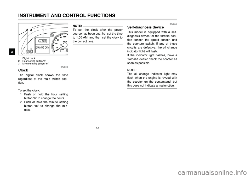
ClockClockThe digital clock shows the time
regardless of the main switch posi-
tion.
To set the clock:
1. Push or hold the hour setting
button “h” to change the hours.
2. Push or hold the minute setting
button “m” to change the min-
utes.
NOTE:
To set the clock after the power
source has been cut, first set the time
to 1:00 AM, and then set the clock to
the correct time.
EAU03840
Self-diagnosis deviceSelf-diagnosis deviceThis model is equipped with a self-
diagnosis device for the throttle posi-
tion sensor, the speed sensor, and
the overturn switch. If any of those
circuits are defective, the oil change
indicator light will flash.
If the indicator light flashes, have a
Yamaha dealer check the scooter as
soon as possible.NOTE:
The oil change indicator light may
flash when the engine is revved with
the scooter on the centerstand, but
this does not indicate a malfunction.
INSTRUMENT AND CONTROL FUNCTIONS
3
1 23
1. Digital clock
2. Hour setting button “h”
3. Minute setting button “m”
5GJ-9-E1 9/4/01 1:27 PM Page 20
Page 25 of 102

3-9
EAU03882
Front brake leverBrake lever, frontThe front brake lever is located on
the right handlebar grip. To apply the
front brake, pull this lever toward the
handlebar grip.INSTRUMENT AND CONTROL FUNCTIONS
3
1
1. Front brake lever
EAU00163
Rear brake leverBrake lever, rearThe rear brake lever is located on the
left handlebar grip. To apply the rear
brake, pull this lever toward the han-
dlebar grip.
1
1. Rear brake lever
EAU03881
Fuel tank capFuel tank capTo remove the fuel tank cap
1. Open the lid by pulling the lever
up.
2. Insert the key into the lock and
turn it clockwise. The lock will be
released and the fuel tank cap
can be removed.
1
1. Lid
5GJ-9-E1 9/4/01 1:27 PM Page 24
Page 26 of 102

3-10
INSTRUMENT AND CONTROL FUNCTIONS
3
To install the fuel tank cap
1. Align the match marks, insert the
fuel tank cap into the tank open-
ing, and then push down on the
cap.
2. Turn the key counterclockwise to
the original position, and then
remove it.
3. Close the lid.
EWA00047
wMake sure that the fuel tank cap is
properly installed and locked in
place before riding the scooter.
1
1. Match marks
EAU03753
FuelFuelMake sure that there is sufficient fuel
in the tank. Fill the fuel tank to the
bottom of the filler tube as shown.
EW000130
w8Do not overfill the fuel tank,
otherwise it may overflow
when the fuel warms up and
expands.
8Avoid spilling fuel on the hot
engine.211. Fuel tank filler tube
2. Fuel level
EAU00185
cCImmediately wipe off spilled fuel
with a clean, dry, soft cloth, since
fuel may deteriorate painted sur-
faces or plastic parts.
5GJ-9-E1 9/4/01 1:27 PM Page 25
Page 27 of 102

3-11
INSTRUMENT AND CONTROL FUNCTIONS
3
EAU04284
ECA00104
cCUse only unleaded gasoline. The
use of leaded gasoline will cause
severe damage to internal engine
parts, such as the valves and pis-
ton rings, as well as to the exhaust
system.
Your Yamaha engine has been
designed to use regular unleaded
gasoline with a research octane num-
ber of 91 or higher. If knocking (or
pinging) occurs, use a gasoline of a
different brand or premium unleaded
fuel. Use of unleaded fuel will extend
spark plug life and reduce mainte-
nance costs.
EAU03802
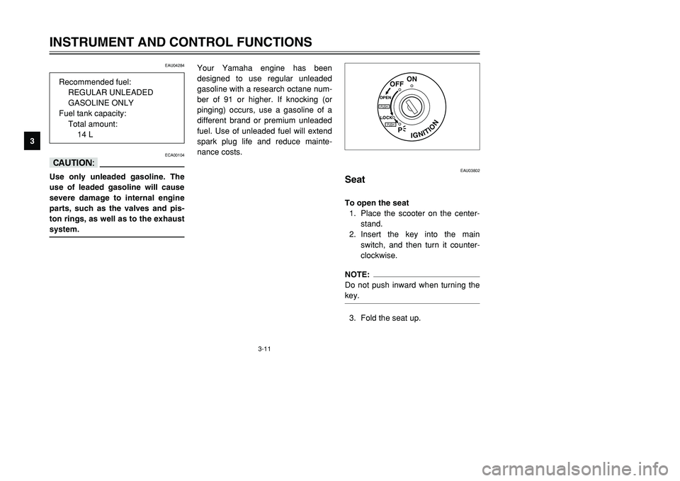
SeatSeatTo open the seat
1. Place the scooter on the center-
stand.
2. Insert the key into the main
switch, and then turn it counter-
clockwise.NOTE:
Do not push inward when turning the
key.3. Fold the seat up.
IGNITION
P
LOCK
ON
OFF
OPENPUSHPUSH
Recommended fuel:
REGULAR UNLEADED
GASOLINE ONLY
Fuel tank capacity:
Total amount:
14 L
5GJ-9-E1 9/4/01 1:27 PM Page 26
Page 78 of 102

6-34
PERIODIC MAINTENANCE AND MINOR REPAIR
6
EAU04404
Replacing the fusesFuses, replacingThe main fuse box is located beside
the battery and can be accessed as
follows:
1. Open the seat. (See page 3-11
for seat opening and closing pro-
cedures.)
2. Remove the battery cover. (See
page 6-32 for battery cover
removal procedures.)
1
1. Battery
If a fuse is blown, replace it as fol-
lows.
1. Turn the key to “OFF” and turn
off the electrical circuit in ques-
tion.
2. Remove the blown fuse, and
then install a new fuse of the
specified amperage.
7
123456
1. Signaling system fuse
2. Headlight fuse
3. Ignition fuse
4. Radiator fan fuse
5. Hazard fuse
6. Clock fuse
7. Spare fuse (×2)
3. Disconnect the negative battery
lead, and then lift the battery as
shown.
The fuse box, which contains the
fuses for the individual circuits, is
located under the battery cover and
can be accessed as follows.
1. Open the seat. (See page 3-11
for seat opening and closing pro-
cedures.)
2. Remove the battery cover by
removing the screws.
12
3
1. Negative battery lead
2. Main fuse box
3. Fuse box
5GJ-9-E1 9/4/01 1:27 PM Page 77
Page 79 of 102

6-35
PERIODIC MAINTENANCE AND MINOR REPAIR
6
EC000103
cCDo not use a fuse of a higher
amperage rating than recommend-
ed to avoid causing extensive
damage to the electrical system
and possibly a fire.3. Turn the key to “ON” and turn on
the electrical circuit in question to
check if the device operates.
4. If the fuse immediately blows
again, have a Yamaha dealer
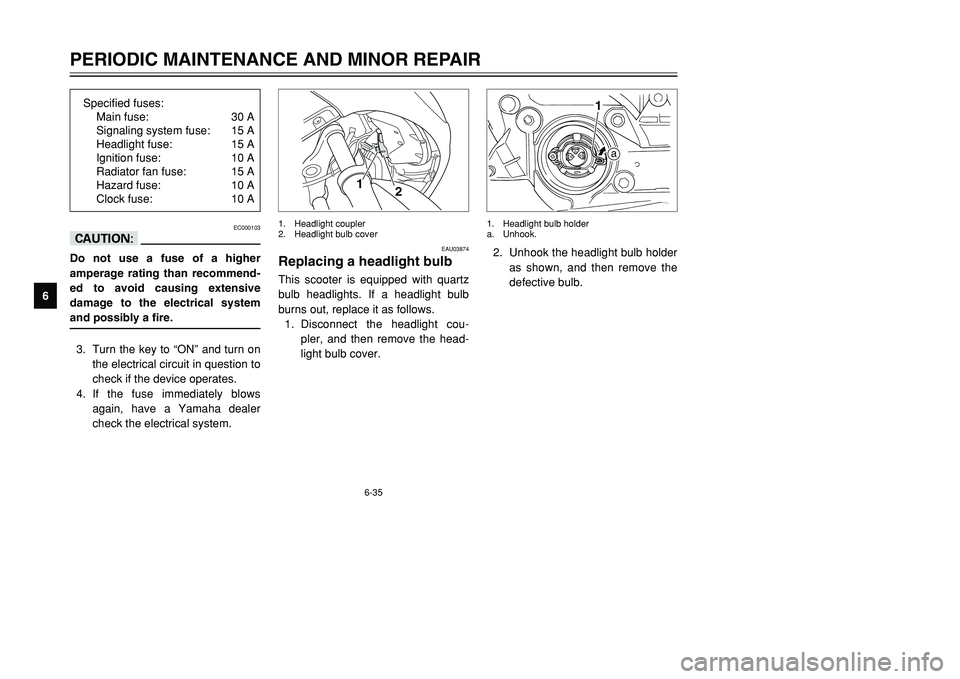
check the electrical system.2. Unhook the headlight bulb holder
as shown, and then remove the
defective bulb.
a
1
1. Headlight bulb holder
a. Unhook.
EAU03874
Replacing a headlight bulbHeadlight bulb, replacingThis scooter is equipped with quartz
bulb headlights. If a headlight bulb
burns out, replace it as follows.
1. Disconnect the headlight cou-
pler, and then remove the head-
light bulb cover.
1
2
1. Headlight coupler
2. Headlight bulb cover
Specified fuses:
Main fuse: 30 A
Signaling system fuse: 15 A
Headlight fuse: 15 A
Ignition fuse: 10 A
Radiator fan fuse: 15 A
Hazard fuse: 10 A
Clock fuse: 10 A
5GJ-9-E1 9/4/01 1:27 PM Page 78
Page 82 of 102

6-38
PERIODIC MAINTENANCE AND MINOR REPAIR
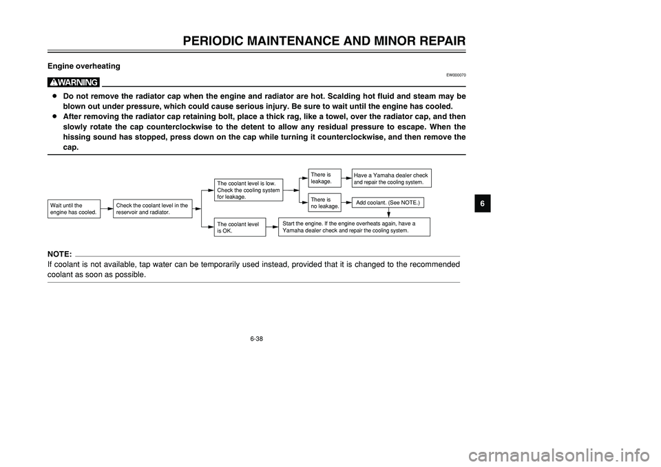
6 Engine overheating
EW000070
w8Do not remove the radiator cap when the engine and radiator are hot. Scalding hot fluid and steam may be
blown out under pressure, which could cause serious injury. Be sure to wait until the engine has cooled.
8After removing the radiator cap retaining bolt, place a thick rag, like a towel, over the radiator cap, and then
slowly rotate the cap counterclockwise to the detent to allow any residual pressure to escape. When the
hissing sound has stopped, press down on the cap while turning it counterclockwise, and then remove the
cap.Wait until the
engine has cooled.
Check the coolant level in the
reservoir and radiator.
The coolant level
is OK.The coolant level is low.
Check the cooling system
for leakage.
Have a Yamaha dealer checkand repair the cooling system.Add coolant. (See NOTE.)
Start the engine. If the engine overheats again,
have a
Yamaha dealer check
and repair the cooling system.
There is
leakage.
There is
no leakage.
NOTE:
If coolant is not available, tap water can be temporarily used instead, provided that it is changed to the recommended
coolant as soon as possible.
5GJ-9-E1 9/4/01 1:27 PM Page 81