YAMAHA TMAX 2015 Owners Manual
Manufacturer: YAMAHA, Model Year: 2015, Model line: TMAX, Model: YAMAHA TMAX 2015Pages: 112, PDF Size: 6.38 MB
Page 101 of 112
SCOOTER CARE AND STORAGE
8-3
1
2
3
4
5
6
789
10
11
12
After cleaning
1. Dry the scooter with a chamois or an absorbing cloth.
2. Use a chrome polish to shine chrome, aluminum and stain-
less-steel parts, including the ex-
haust system. (Even the thermally
induced discoloring of stain-
less-steel exhaust systems can be
removed through polishing.)
3. To prevent corrosion, it is recom- mended to apply a corrosion pro-
tection spray on all metal,
including chrome- and nickel-plat-
ed, surfaces.
4. Use spray oil as a universal clean- er to remove any remaining dirt.
5. Touch up minor paint damage caused by stones, etc.
6. Wax all painted surfaces.
7. Let the scooter dry completely be- fore storing or covering it.
WARNING
EWA10943
Contaminants on the brakes or tires
can cause loss of control.
Make sure that there is no oil or
wax on the brakes or tires. If
necessary, clean the brake discs and brake linings with a
regular brake disc cleaner or ac-
etone, and wash the tires with
warm water and a mild deter-
gent.
Before operating the scooter
test its braking performanceand cornering behavior.
NOTICE
ECA10801
Apply spray oil and wax spar-
ingly and make sure to wipe off
any excess.
Never apply oil or wax to any
rubber and plastic parts, but
treat them with a suitable care
product.
Avoid using abrasive polishing
compounds as they will wearaway the paint.
TIP
Consult a Yamaha dealer for ad-
vice on what products to use.
Washing, rainy weather or humid
climates can cause the headlight
lens to fog. Turning the headlight
on for a short period of time will
help remove the moisture from the
lens.
2PW-9-E0_1.book 3 ページ 2015年2月19日 木曜日 午後3時30分
Page 102 of 112
SCOOTER CARE AND STORAGE
8-4
1
2
3
4
5
6
78
9
10
11
12
EAU36554
StorageShort-term
Always store your scooter in a cool, dry
place and, if necessary, protect it
against dust with a porous cover. Be
sure the engine and the exhaust sys-
tem are cool before covering the scoot-
er.NOTICE
ECA10821
Storing the scooter in a poorly
ventilated room or covering it
with a tarp, while it is still wet,
will allow water and humidity to
seep in and cause rust.
To prevent corrosion, avoid
damp cellars, stables (because
of the presence of ammonia)
and areas where strong chemi-cals are stored.
Long-term
Before storing your scooter for several
months: 1. Follow all the instructions in the “Care” section of this chapter. 2. Fill up the fuel tank and add fuel
stabilizer (if available) to prevent
the fuel tank from rusting and the
fuel from deteriorating.
3. Perform the following steps to pro- tect the cylinders, piston rings, etc.
from corrosion.
a. Remove the spark plug caps and the spark plugs.
b. Pour a teaspoonful of engine oil into the spark plug bores.
c. Install the spark plug caps onto the spark plugs, and then place
the spark plugs on the cylinder
head so that the electrodes are
grounded. (This will limit spark-
ing during the next step.)
d. Turn the engine over several times with the starter. (This will
coat the cylinder walls with oil.)
e. Remove the spark plug caps from the spark plugs, and then
install the spark plugs and the
spark plug caps. WARNING!
To prevent damage or injury
from sparking, make sure to
ground the spark plug elec-
trodes while turning the en-
gine over.
[EWA10952]
4. Lubricate all control cables and the pivoting points of all levers and
pedals as well as of the sidestand/
centerstand.
5. Check and, if necessary, correct the tire air pressure, and then lift
the scooter so that both of its
wheels are off the ground. Alterna-
tively, turn the wheels a little every
month in order to prevent the tires
from becoming degraded in one
spot.
6. Cover the muffler outlet with a plastic bag to prevent moisture
from entering it.
7. Remove the battery and fully charge it. Store it in a cool, dry
place and charge it once a month.
Do not store the battery in an ex-
cessively cold or warm place [less
than 0 C (30 F) or more than 30
C (90 F)]. For more information
on storing the battery, see page
7-28.TIPMake any necessary repairs beforestoring the scooter.
2PW-9-E0_1.book 4 ページ 2015年2月19日 木曜日 午後3時30分
Page 103 of 112
9-1
1
2
3
4
5
6
7
8910
11
12
SPECIFICATIONS
EAU5091R
Dimensions:Overall length:2200 mm (86.6 in)
Overall width: 775 mm (30.5 in)
Overall height: 1420/1475 mm (55.9/58.1 in)
Seat height:
800 mm (31.5 in)
Wheelbase: 1580 mm (62.2 in)
Ground clearance: 125 mm (4.92 in)
Minimum turning radius:
2800 mm (110.2 in)Weight:Curb weight:XP500 219 kg (483 lb)
XP500A 222 kg (489 lb)Engine:Engine type:Liquid cooled 4-stroke, DOHC
Cylinder arrangement: Inline 2-cylinder
Displacement: 530 cm
3
Bore stroke:
68.0 73.0 mm (2.68 2.87 in)
Compression ratio: 10.9 : 1
Starting system: Electric starter
Lubrication system:
Dry sump
Engine oil:Recommended brand:YAMALUBE
Type: SAE 10W-30 or 10W-40
Recommended engine oil grade: API service SG type or higher, JASO stan-
dard MA
Engine oil quantity: Without oil filter ca rtridge replacement:
2.70 L (2.85 US qt, 2.38 Imp.qt)
With oil filter cartridge replacement: 2.90 L (3.07 US qt, 2.55 Imp.qt)Coolant quantity:Coolant reservoir (up to the maximum level
mark):
0.27 L (0.29 US qt, 0.24 Imp.qt)
Radiator (including all routes): 1.50 L (1.59 US qt, 1.32 Imp.qt)Air filter:Air filter element:
Oil-coated paper elementFuel:Recommended fuel:Regular unleaded gasoli ne (Gasohol (E10)
acceptable)
Fuel tank capacity: 15.0 L (3.96 US gal, 3.30 Imp.gal)
Fuel reserve amount:
3.0 L (0.79 US gal, 0.66 Imp.gal)Fuel injection:Throttle body:ID mark:59C1 00
Spark plug(s):Manufacturer/model:
NGK/CR7E
Spark plug gap: 0.7–0.8 mm (0.028–0.031 in)Clutch:Clutch type:
Wet, multiple-disc automaticTransmission:Primary reduction ratio:1.000
Final drive:
Belt
Secondary reduction ratio: 6.034 (52/32 x 36/22 x 59/26)
Transmission type: V-belt automaticChassis:Frame type:Diamond
Caster angle: 25.00
Trail:
92 mm (3.6 in)Front tire:Type:Tubeless
Size:
120/70R15 M/C 56H
Manufacturer/model: DUNLOP/GPR-100FRear tire:Type:
Tubeless
2PW-9-E0_1.book 1 ページ 2015年2月19日 木曜日 午後3時30分
Page 104 of 112
SPECIFICATIONS
9-2
1
2
3
4
5
6
7
89
10
11
12
Size: 160/60R15 M/C 67H
Manufacturer/model:
DUNLOP/GPR-100Loading:Maximum load:XP500 196 kg (432 lb)
XP500A 193 kg (425 lb)
* (Total weight of rider, passenger, cargo and accessories)Tire air pressure (measured on cold
tires):Loading condition:0–90 kg (0–198 lb)
Front:225 kPa (2.25 kgf/cm
2, 33 psi)
Rear: 250 kPa (2.50 kgf/cm2, 36 psi)
Loading condition: XP500 90–196 kg (198–432 lb)
XP500A 90–193 kg (198–425 lb)
Front:225 kPa (2.25 kgf/cm2, 33 psi)
Rear:
280 kPa (2.80 kgf/cm2, 41 psi)
Front wheel:Wheel type: Cast wheel
Rim size:
15M/C x MT3.50Rear wheel:Wheel type:Cast wheel Rim size:
15M/C x MT5.00
Front brake:Type:Dual disc brake
Operation: Right hand operation
Specified brake fluid:
DOT 4Rear brake:Type:Single disc brake
Operation:
Left hand operation
Specified brake fluid: DOT 4Front suspension:Type:
Telescopic fork
Spring/shock absorber type: Coil spring/oil damper
Wheel travel: 120 mm (4.7 in)Rear suspension:Type:Swingarm
Spring/shock absorber type: Coil spring/gas-oil damper
Wheel travel:
116 mm (4.6 in)Electrical system:Ignition system:TCI Charging system:
AC magneto
Battery:Model:YTZ12S
Voltage, capacity: 12 V, 11.0 AhBulb voltage, wattage quantity:Headlight:
LED
Tail/brake light: LED
Front turn signal light:
12 V, 21.0 W 2
Rear turn signal light: 12 V, 21.0 W 2
Auxiliary light: LED
License plate light:
12 V, 5.0 W 1
Meter lighting: LED
High beam indicator light: LED
Turn signal indicator light:
LED
Engine trouble warning light: LED
ABS warning light: XP500A LED
Smart key system indicator light:
LED
2PW-9-E0_1.book 2 ページ 2015年2月19日 木曜日 午後3時30分
Page 105 of 112
SPECIFICATIONS
9-3
1
2
3
4
5
6
7
8910
11
12
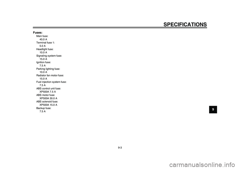
Fuses:Main fuse:40.0 A
Terminal fuse 1: 5.0 A
Headlight fuse: 10.0 A
Signaling system fuse:
15.0 A
Ignition fuse: 7.5 A
Parking lighting fuse: 10.0 A
Radiator fan motor fuse:
15.0 A
Fuel injection system fuse: 7.5 A
ABS control unit fuse: XP500A 7.5 A
ABS motor fuse:
XP500A 30.0 A
ABS solenoid fuse: XP500A 15.0 A
Backup fuse: 7.5 A
2PW-9-E0_1.book 3 ページ 2015年2月19日 木曜日 午後3時30分
Page 106 of 112
10-1
1
2
3
4
5
6
7
8
910
11
12
CONSUMER INFORMATION
EAU53562
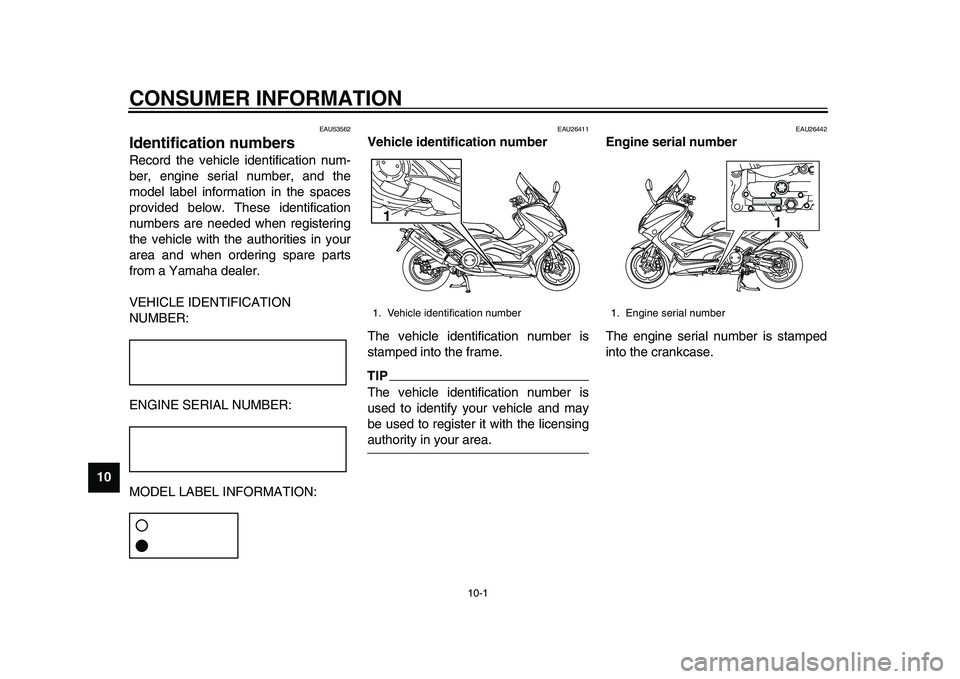
Identification numbersRecord the vehicle identification num-
ber, engine serial number, and the
model label information in the spaces
provided below. These identification
numbers are needed when registering
the vehicle with the authorities in your
area and when ordering spare parts
from a Yamaha dealer.
VEHICLE IDENTIFICATION
NUMBER:
ENGINE SERIAL NUMBER:
MODEL LABEL INFORMATION:
EAU26411
Vehicle identification number
The vehicle identification number is
stamped into the frame.TIPThe vehicle identification number is
used to identify your vehicle and may
be used to register it with the licensingauthority in your area.
EAU26442
Engine serial number
The engine serial number is stamped
into the crankcase.
1. Vehicle identification number1
1. Engine serial number
1
2PW-9-E0_1.book 1 ページ 2015年2月19日 木曜日 午後3時30分
Page 107 of 112
CONSUMER INFORMATION
10-2
1
2
3
4
5
6
7
8
91011
12
EAU26501
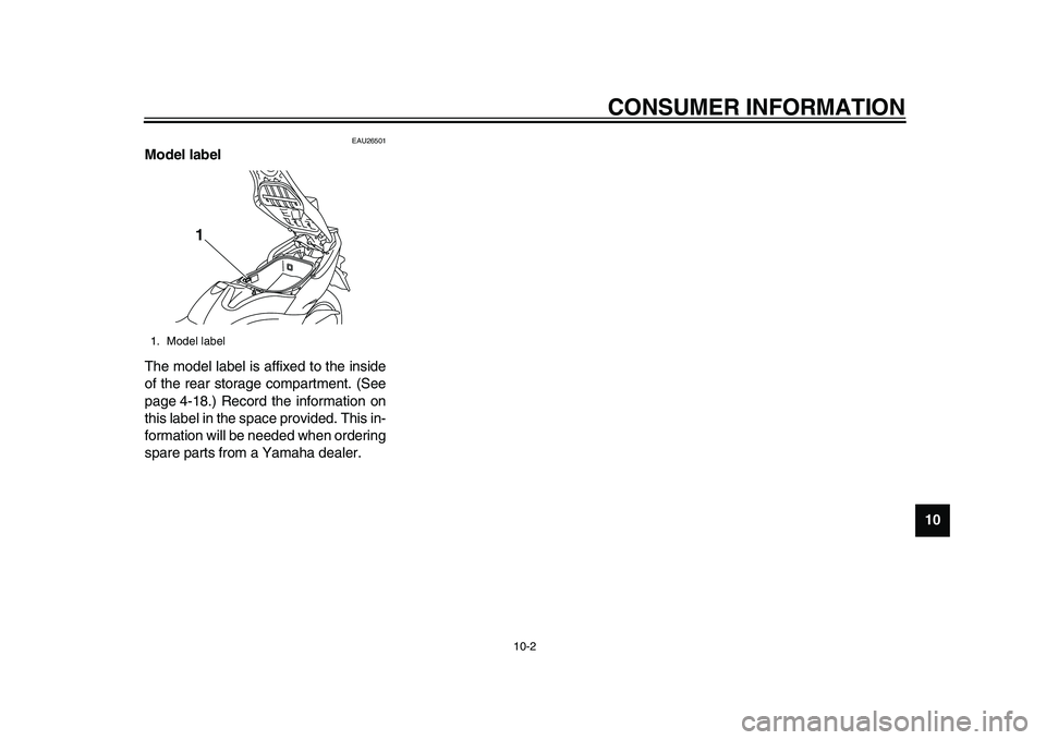
Model label
The model label is affixed to the inside
of the rear storage compartment. (See
page 4-18.) Record the information on
this label in the space provided. This in-
formation will be needed when ordering
spare parts from a Yamaha dealer.1. Model label
1
2PW-9-E0_1.book 2 ページ 2015年2月19日 木曜日 午後3時30分
Page 108 of 112
11-1
1
2
3
4
5
6
7
8
9
1011
12
INDEXAABS (for ABS models) .............................4-13
ABS warning light (for ABS models) ..........4-1
Acceleration and deceleration....................6-3
Air filter element, replacing ......................7-16
Auxiliary DC connector ............................4-25
Auxiliary light ............................................7-32BBattery......................................................7-28
Brake fluid, changing ...............................7-24
Brake fluid level, checking .......................7-23
Brake lever, front......................................4-11
Brake lever, rear ......................................4-11
Brake levers, lubricating...........................7-25
Braking .......................................................6-3CCables, checking and lubricating .............7-25
Care ...........................................................8-1
Catalytic converter ...................................4-16
Centerstand and sidestand, checking and lubricating .......................................7-26
Coolant.....................................................7-14DDimmer switch .........................................4-10
Drive belt slack.........................................7-24EEmergency mode .....................................7-38
Engine break-in ..........................................6-4
Engine idling speed..................................7-16
Engine oil and oil filter cartridge ...............7-11
Engine serial number ...............................10-1
Engine stop switch ...................................4-10
Engine trouble warning light.......................4-1
FFront and rear brak e lever free play,
checking ................................................ 7-20
Front and rear brake pads, checking ....... 7-22
Front fork, checking ................................. 7-27
Fuel.......................................................... 4-15
Fuel consumption, tips for reducing........... 6-4
Fuel tank cap ........................................... 4-14
Fuses, replacing ...................................... 7-29HHandlebar switches ................................... 4-9
Hazard switch .......................................... 4-10
Headlights................................................ 7-31
Helmet holder .......................................... 4-17
High beam indicator light ........................... 4-1
Horn switch .............................................. 4-10
How to lock the steering ............................ 3-9IIdentification numbers ............................. 10-1
Ignition circuit cut-off system ................... 4-23
Indicator lights and warning lights ............. 4-1KKey, handling of smart and mechanical
key........................................................... 3-3LLicense plate light bulb, replacing ........... 7-33MMaintenance and lubrication, periodic ....... 7-4
Maintenance, emission control system...... 7-3
Matte color, caution ................................... 8-1
Model label .............................................. 10-2
Multi-function display ................................. 4-3OON/Start switch........................................ 4-10 Operating range of the smart key
system .................................................... 3-2
PPanels, removing and installing ................ 7-8
Parking ...................................................... 6-5
Parking mode .......................................... 3-10
Part locations ............................................ 2-1
Pass switch ............................................. 4-10
Powering off the vehicle ............................ 3-8RRear brake lock cable, adjusting ............. 7-21
Rear brake lock, checking ....................... 7-22
Rear brake lock lever .............................. 4-12
Rear view mirrors .................................... 4-21
Rider backrest, adjusting......................... 4-17SSafe-riding points ...................................... 1-5
Safety information ..................................... 1-1
Seat opening and closing .......................... 3-9
Shock absorber assembly ....................... 4-22
Sidestand ................................................ 4-22
Smart key .................................................. 3-5
Smart key battery, replacing ..................... 3-6
Smart key system...................................... 3-1
Smart key system indicator light ............... 4-2
Spark plugs, checking ............................. 7-10
Specifications ............................................ 9-1
Speedometer............................................. 4-2
Starting off ................................................. 6-2
Starting the engine .................................... 6-1
Steering, checking................................... 7-27
Storage...................................................... 8-4
Storage compartments ............................ 4-18
2PW-9-E0_1.book 1 ページ 2015年2月19日 木曜日 午後3時30分
Page 109 of 112
INDEX
11-2
1
2
3
4
5
6
7
8
9
101112
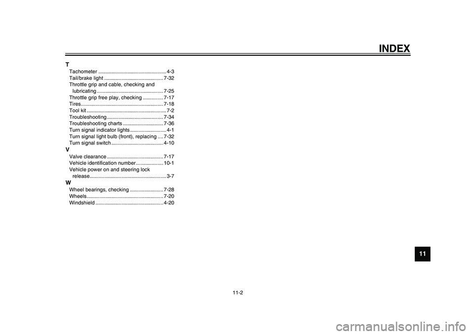
TTachometer ............................................... 4-3
Tail/brake light ......................................... 7-32
Throttle grip and cable, checking and lubricating .............................................. 7-25
Throttle grip free play, checking .............. 7-17
Tires......................................................... 7-18
Tool kit ....................................................... 7-2
Troubleshooting ....................................... 7-34
Troubleshooting charts ............................ 7-36
Turn signal indicator lights ......................... 4-1
Turn signal light bulb (front), replacing .... 7-32
Turn signal switch .................................... 4-10VValve clearance ....................................... 7-17
Vehicle identification number................... 10-1
Vehicle power on and steering lock release..................................................... 3-7WWheel bearings, c hecking ....................... 7-28
Wheels..................................................... 7-20
Windshield ............................................... 4-20
2PW-9-E0_1.book 2 ページ 2015年2月19日 木曜日 午後3時30分
Page 110 of 112

2PW-9-E0_1.book 3 ページ 2015年2月19日 木曜日 午後3時30分