key battery YAMAHA TMAX 2015 Owners Manual
[x] Cancel search | Manufacturer: YAMAHA, Model Year: 2015, Model line: TMAX, Model: YAMAHA TMAX 2015Pages: 112, PDF Size: 6.38 MB
Page 8 of 112
TABLE OF CONTENTSSAFETY INFORMATION................... 1-1
Further safe-riding points................. 1-5
DESCRIPTION ................................... 2-1
Left view .......................................... 2-1
Right view ........................................ 2-2
Controls and instrument s................. 2-3
SMART KEY SYSTEM ....................... 3-1
Smart key system ......... ................... 3-1
Operating range of the smart key
system ....................... ................... 3-2
Handling of the smart key and mechanical key ............................ 3-3
Smart key ........................................ 3-5
Replacing the smart key battery ...... 3-6
Vehicle power on and steering lock release .................................. 3-7
Powering off th e vehicle .................. 3-8
How to lock the steering .................. 3-9
Seat opening and closin g ................ 3-9
Parking mode ................................ 3-10
INSTRUMENT AND CONTROL
FUNCTIONS ....................................... 4-1
Indicator lights and warning lights ... 4-1
Speedometer ................................... 4-2
Tachometer ..................................... 4-3
Multi-function display ....................... 4-3
Handlebar switches ......................... 4-9
Front brake lever ........................... 4-11 Rear brake lever............................ 4-11
Rear brake lock lever .................... 4-12
ABS (for ABS models)...
................ 4-13
Fuel tank cap................................. 4-14
Fuel ............................................... 4-15
Catalytic converter ........................ 4-16
Adjusting the rider backrest........... 4-17
Helmet holder ................................ 4-17
Storage compartments .................. 4-18
Windshield..................................... 4-20
Rear view mirrors .......................... 4-21
Shock absorber assembly ............. 4-22
Sidestand ...................................... 4-22
Ignition circuit cut- off system ......... 4-23
Auxiliary DC connector.................. 4-25
FOR YOUR SAFETY –
PRE-OPERATION CHECKS ............. 5-1
OPERATION AND IMPORTANT
RIDING POINTS ................................. 6-1
Starting the engine .......................... 6-1
Starting off ....................................... 6-2
Acceleration and deceleration ......... 6-3
Braking ............................................ 6-3
Tips for reducing fuel consumption ................................ 6-4
Engine break-in ............................... 6-4
Parking ............................................ 6-5 PERIODIC MAINTENANCE AND
ADJUSTMENT
.................................... 7-1
Owner’s tool kit ................................ 7-2
Periodic maintenance chart for the emission control syst em ............... 7-3
General maintenance and lubrication chart ............................ 7-4
Removing and installing panels ....... 7-8
Checking the spark plugs .............. 7-10
Engine oil and oil filt er cartridge..... 7-11
Coolant .......................................... 7-14
Replacing the air filter element ...... 7-16
Adjusting the engine idling speed............ ............................ .. 7-16
Checking the throttle grip free play ............................................. 7-17
Valve clearance ............................. 7-17
Tires ............................................... 7-18
Cast wheels ................................... 7-20
Checking the front and rear brake
lever free play ............................. 7-20
Adjusting the rear brake lock cable ........................................... 7-21
Checking the rear brake lock ......... 7-22
Checking the front and rear brake pads............................................ 7-22
Checking the brake fluid level ........ 7-23
Changing the brake fluid ................ 7-24
Drive belt slack .............................. 7-24
Checking and lubricating the
cables
......................................... 7-25
2PW-9-E0_1.book 1 ページ 2015年2月19日 木曜日 午後3時30分
Page 20 of 112
SMART KEY SYSTEM
3-3
1
23
4
5
6
7
8
9
10
11
12 range may be affected by the sur-
rounding environment.
When the battery of the smart key
is discharged, the smart key may
not work or its operating range be-
come very small.
If the smart key is turned off, the
vehicle will not recognize the smart
key even if it is within operating
range.
If the “ON/ ” switch, “OFF/LOCK”
switch, or “SEAT OPEN/ ”
switch are repeatedly pressed
when the smart key is out of range
or cannot communicate with the
vehicle, all switches will be tempo-
rarily disabled.
Placing the smart key in the front
or rear storage compartment may
block communication between the
smart key and the vehicle. If the
rear trunk is locked with the smart
key inside, the smart key system
may be disabled. The smart key
should always be carried on your
person.
When leaving the vehicle, make
sure you apply the steering lock
and take the smart key with you. It is recommended that you turn the
smart key off.
EAU61643
Handling of the
smart key and
mechanical key
WARNING
EWA17952
The smart key should be carried
with you. Do not store it on the
vehicle.
When the smart key is within op-
erating range, exercise due care
because other people not carry-
ing the smart key can start theengine and operate the vehicle.
Included with the vehicle is one smart
key (with a built-in mechanical key) and
one spare mechanical key with an iden-
tification tag. Keep the spare mechani-
cal key and tag separate from the smart
key. Should you lose or damage the
smart key, or when its battery is dis-
charged, the mechanical key will serve
as a back up. The seat can be opened,
the smart key system identification
number can be manually input, and
then the vehicle can be operated. (See
page 7-38.) We recommend that you
note down the identification number
in case of emergency.
2PW-9-E0_1.book 3 ページ 2015年2月19日 木曜日 午後3時30分
Page 21 of 112
SMART KEY SYSTEM
3-4
1
234
5
6
7
8
9
10
11
12
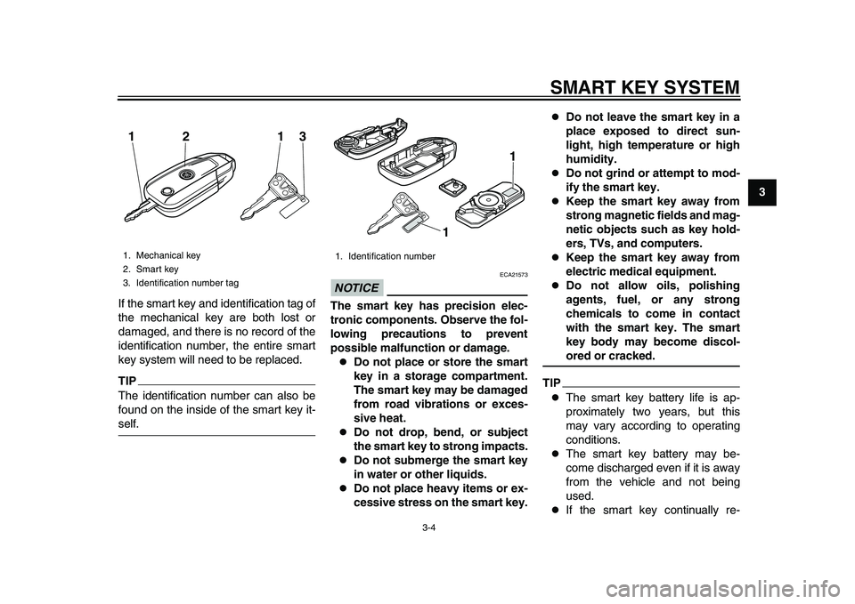
If the smart key and identification tag of
the mechanical key are both lost or
damaged, and there is no record of the
identification number, the entire smart
key system will need to be replaced.
TIPThe identification number can also be
found on the inside of the smart key it-self.
NOTICE
ECA21573
The smart key has precision elec-
tronic components. Observe the fol-
lowing precautions to prevent
possible malfunction or damage.
Do not place or store the smart
key in a storage compartment.
The smart key may be damaged
from road vibrations or exces-
sive heat.
Do not drop, bend, or subject
the smart key to strong impacts.
Do not submerge the smart key
in water or other liquids.
Do not place heavy items or ex-
cessive stress on the smart key.
Do not leave the smart key in a
place exposed to direct sun-
light, high temperature or high
humidity.
Do not grind or attempt to mod-
ify the smart key.
Keep the smart key away from
strong magnetic fields and mag-
netic objects such as key hold-
ers, TVs, and computers.
Keep the smart key away from
electric medical equipment.
Do not allow oils, polishing
agents, fuel, or any strong
chemicals to come in contact
with the smart key. The smart
key body may become discol-ored or cracked.
TIP
The smart key battery life is ap-
proximately two years, but this
may vary according to operating
conditions.
The smart key battery may be-
come discharged even if it is away
from the vehicle and not being
used.
If the smart key continually re-
1. Mechanical key
2. Smart key
3. Identification number tag12 13
1. Identification number
1
1
2PW-9-E0_1.book 4 ページ 2015年2月19日 木曜日 午後3時30分
Page 22 of 112
SMART KEY SYSTEM
3-5
1
23
4
5
6
7
8
9
10
11
12 ceives radio waves, the smart key
battery will discharge quickly. (For
example, when placed in the vicin-
ity of electrical products such as
televisions, radios, or computers.)
Replace the smart key battery when
the smart key system indicator light
flashes for about 20 seconds when the
power of the vehicle is turned on or
when the smart key indicator light does
not come on when the “ON/OFF”
switch is pushed. (See page 3-6.) After
changing the smart key battery, if the
smart key system still does not operate,
have a Yamaha dealer check the vehi-
cle.
TIPYou can register up to six smart keys
for the same vehicle. See a Yamahadealer regarding spare smart keys.
EAU61673
Smart keyWhen the smart key is turned on and
brought within range, the smart key
system allows you to operate the vehi-
cle without inserting a mechanical key.
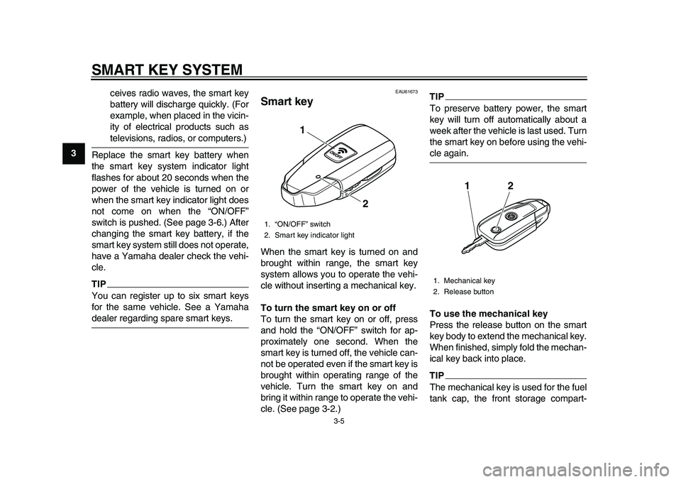
To turn the smart key on or off
To turn the smart key on or off, press
and hold the “ON/OFF” switch for ap-
proximately one second. When the
smart key is turned off, the vehicle can-
not be operated even if the smart key is
brought within operating range of the
vehicle. Turn the smart key on and
bring it within range to operate the vehi-
cle. (See page 3-2.)
TIPTo preserve battery power, the smart
key will turn off automatically about a
week after the vehicl e is last used. Turn
the smart key on before using the vehi-cle again.
To use the mechanical key
Press the release button on the smart
key body to extend the mechanical key.
When finished, simply fold the mechan-
ical key back into place.TIPThe mechanical key is used for the fuel
tank cap, the front storage compart-
1. “ON/OFF” switch
2. Smart key indicator light
1
2
1. Mechanical key
2. Release button
12
2PW-9-E0_1.book 5 ページ 2015年2月19日 木曜日 午後3時30分
Page 23 of 112
SMART KEY SYSTEM
3-6
1
234
5
6
7
8
9
10
11
12
ment, and the seat lock. (See page
4-14, 4-18, and 7-38.)
EAU61603
Replacing the smart key
batteryReplace the battery in the following sit-
uations.
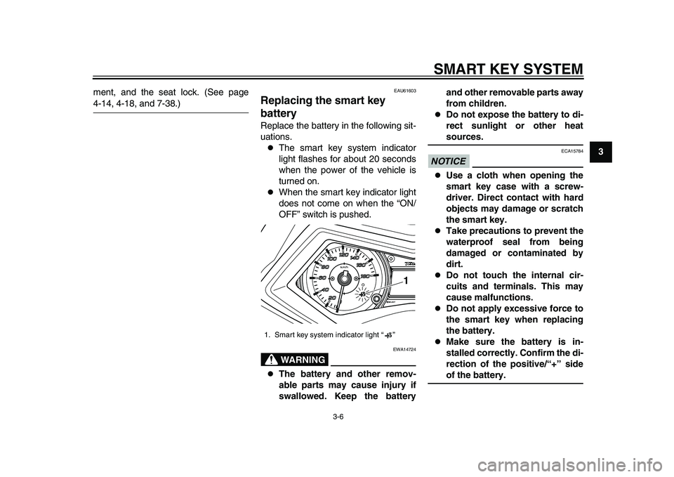
The smart key system indicator
light flashes for about 20 seconds
when the power of the vehicle is
turned on.
When the smart key indicator light
does not come on when the “ON/
OFF” switch is pushed.WARNING
EWA14724
The battery and other remov-
able parts may cause injury if
swallowed. Keep the battery and other removable parts away
from children.
Do not expose the battery to di-
rect sunlight or other heatsources.
NOTICE
ECA15784
Use a cloth when opening the
smart key case with a screw-
driver. Direct contact with hard
objects may damage or scratch
the smart key.
Take precautions to prevent the
waterproof seal from being
damaged or contaminated by
dirt.
Do not touch the internal cir-
cuits and terminals. This may
cause malfunctions.
Do not apply excessive force to
the smart key when replacing
the battery.
Make sure the battery is in-
stalled correctly. Confirm the di-
rection of the positive/“+” sideof the battery.
1. Smart key system indicator light “ ”
1
2PW-9-E0_1.book 6 ページ 2015年2月19日 木曜日 午後3時30分
Page 24 of 112
SMART KEY SYSTEM
3-7
1
23
4
5
6
7
8
9
10
11
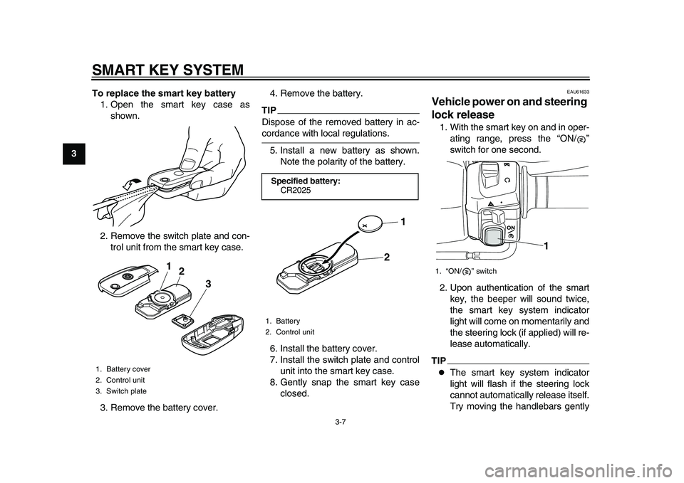
12 To replace the smart key battery
1. Open the smart key case as shown.
2. Remove the switch plate and con- trol unit from the smart key case.
3. Remove the battery cover. 4. Remove the battery.
TIPDispose of the removed battery in ac-cordance with local regulations.
5. Install a new battery as shown. Note the polarity of the battery.
6. Install the battery cover.
7. Install the switch plate and control unit into the smart key case.
8. Gently snap the smart key case closed.
EAU61633
Vehicle power on and steering
lock release1. With the smart key on and in oper-ating range, press the “ON/ ”
switch for one second.
2. Upon authentication of the smart key, the beeper will sound twice,
the smart key system indicator
light will come on momentarily and
the steering lock (if applied) will re-
lease automatically.TIP
The smart key system indicator
light will flash if the steering lock
cannot automatically release itself.
Try moving the handlebars gently
1. Battery cover
2. Control unit
3. Switch plate
3
1
2
Specified battery:
CR20251. Battery
2. Control unit
2 1
1. “ON/ ” switch
1
2PW-9-E0_1.book 7 ページ 2015年2月19日 木曜日 午後3時30分
Page 27 of 112
SMART KEY SYSTEM
3-10
1
234
5
6
7
8
9
10
11
12
WARNING
EWA17941
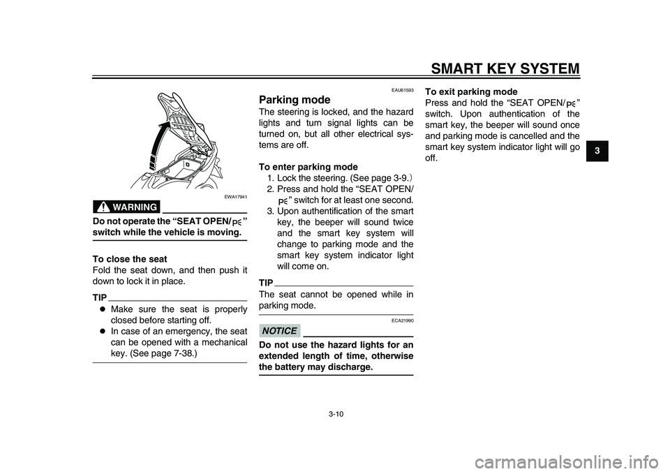
Do not operate the “SEAT OPEN/ ”switch while the vehicle is moving.
To close the seat
Fold the seat down, and then push it
down to lock it in place.TIP
Make sure the seat is properly
closed before starting off.
In case of an emergency, the seat
can be opened with a mechanicalkey. (See page 7-38.)
EAU61593
Parking modeThe steering is locked, and the hazard
lights and turn signal lights can be
turned on, but all other electrical sys-
tems are off.
To enter parking mode 1. Lock the steering. (See page 3-9. )
2. Press and hold the “SEAT OPEN/ ” switch for at least one second.
3. Upon authentification of the smart key, the beeper will sound twice
and the smart key system will
change to parking mode and the
smart key system indicator light
will come on.TIPThe seat cannot be opened while inparking mode.NOTICE
ECA21990
Do not use the hazard lights for an
extended length of time, otherwisethe battery may discharge. To exit parking mode
Press and hold the “SEAT OPEN/ ”
switch. Upon authentication of the
smart key, the beeper will sound once
and parking mode is cancelled and the
smart key system indicator light will go
off.
2PW-9-E0_1.book 10 ページ 2015年2月19日 木曜日 午後3時30分
Page 46 of 112
INSTRUMENT AND CONTROL FUNCTIONS
4-19
1
2
34
5
6
7
8
9
10
11
12
TIP
Some helmets cannot be stored in
the rear storage compartment be-
cause of their size or shape.
Do not leave your scooter unat-
tended with the seat open.
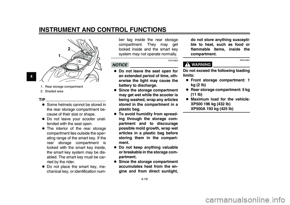
The interior of the rear storage
compartment lies outside the oper-
ating range of the smart key. If the
rear storage compartment is
locked with the smart key inside,
the smart key system may be dis-
abled. The smart key must be car-
ried by the rider.
Do not place the smart key, me-
chanical key, or identification num- ber tag inside the rear storage
compartment. They may get
locked inside and the smart key
system may not operate normally.
NOTICE
ECA15963
Do not leave the seat open for
an extended period of time, oth-
erwise the light may cause the
battery to discharge.
Since the storage compartment
may get wet while the scooter is
being washed, wrap any articles
stored in the compartment in a
plastic bag.
To avoid humidity from spread-
ing through the storage com-
partment and to discourage
possible mold growth, wrap wet
articles in a plastic bag before
storing them in the compart-
ment.
Do not keep anything valuable
or breakable in the storage com-
partment.
Since the storage compartment
accumulates heat from the en-
gine and from direct sunlight,
do not store anything suscepti-
ble to heat, such as food or
flammable items, inside the
compartment.WARNING
EWA15861
Do not exceed the following loading
limits:
Front storage compartment: 1
kg (2 lb)
Rear storage compartment: 5 kg
(11 lb)
Maximum load for the vehicle:
XP500 196 kg (432 lb)XP500A 193 kg (425 lb)
1. Rear storage compartment
2. Shaded area
1
2
2PW-9-E0_1.book 19 ページ 2015年2月19日 木曜日 午後3時30分
Page 93 of 112
PERIODIC MAINTENANCE AND ADJUSTMENT
7-34
1
2
3
4
5
678
9
10
11
12
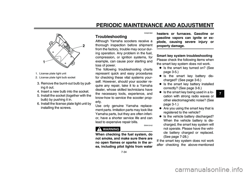
3. Remove the burnt-out bulb by pull-
ing it out.
4. Insert a new bulb into the socket.
5. Install the socket (together with the bulb) by pushing it in.
6. Install the license plate light unit by installing the screws.
EAU61562
TroubleshootingAlthough Yamaha scooters receive a
thorough inspection before shipment
from the factory, trouble may occur dur-
ing operation. Any problem in the fuel,
compression, or ignition systems, for
example, can cause poor starting and
loss of power.
The following troubleshooting charts
represent quick and easy procedures
for checking these vital systems your-
self. However, should your scooter re-
quire any repair, take it to a Yamaha
dealer, whose skilled technicians have
the necessary tools, experience, and
know-how to service the scooter prop-
erly.
Use only genuine Yamaha replace-
ment parts. Imitation parts may look like
Yamaha parts, but they are often inferi-
or, have a shorter service life and can
lead to expensive repair bills.
WARNING
EWA15142
When checking the fuel system, do
not smoke, and make sure there are
no open flames or sparks in the ar-
ea, including pilot lights from water heaters or furnaces. Gasoline or
gasoline vapors can ignite or ex-
plode, causing severe injury or
property damage.
Smart key system troubleshooting
Please check the following items when
the smart key system does not work.
Is the smart key turned on? (See
page 3-5.)
Is the smart key battery dis-
charged? (See page 3-6.)
Is the smart key battery installed
correctly? (See page 3-6.)
Is the smart key being used in a lo-
cation with strong radio waves or
other electromagnetic noise? (See
page 3-1.)
Are you using the smart key that is
registered to the vehicle?
Is the vehicle battery discharged?
When the vehicle battery is dis-
charged, the smart key system will
not operate. Please have the vehi-
cle battery charged or replaced.
(See page 7-28.)
If the smart key system does not work
after checking the above-mentioned
1. License plate light unit
2. License plate light bulb socket
1 2
2PW-9-E0_1.book 34 ページ 2015年2月19日 木曜日 午後3時30分
Page 97 of 112
PERIODIC MAINTENANCE AND ADJUSTMENT
7-38
1
2
3
4
5
678
9
10
11
12
EAU61545
Emergency modeWhen the smart key is lost, damaged,
or its battery has discharged, the vehi-
cle can still be turned on and the engine
started. You will need a mechanical key
and the smart key system identification
number. (See page 3-3.) To operate
the vehicle in emergency mode, carry
out the following steps.TIPEmergency mode operation will be
cancelled if the respective steps are not
carried out within the time set for each
operation or if the “OFF/LOCK” switchis pushed. 1. Stop the vehicle in a safe place.
2. Unlock the seat by inserting the mechanical key into the lock inside
the front storage compartment and
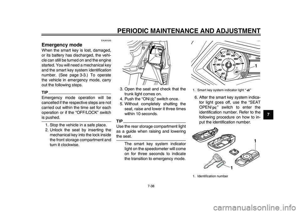
turn it clockwise. 3. Open the seat and check that the
trunk light comes on.
4. Push the “ON/ ” switch once.
5. Without completely shutting the seat, raise and lower it three times
within 10 seconds.
TIPUse the rear storage compartment light
as a guide when raising and loweringthe seat.
The smart key system indicator
light on the speedometer will come
on for three seconds to indicate
the transition to emergency mode. 6. After the smart key system indica-
tor light goes off, use the “SEAT
OPEN/ ” switch to enter the
identification number. Refer to the
following procedure on how to in-
put the identification number.
1. Smart key system indicator light “ ”
1. Identification number
1
1 1
2PW-9-E0_1.book 38 ページ 2015年2月19日 木曜日 午後3時30分