beam YAMAHA TRICITY 300 2021 Owners Manual
[x] Cancel search | Manufacturer: YAMAHA, Model Year: 2021, Model line: TRICITY 300, Model: YAMAHA TRICITY 300 2021Pages: 112, PDF Size: 15.18 MB
Page 30 of 112

Instrument and control functions
5-1
5
EAU4939P
In dicator li ghts an d warnin g
li g hts
EAU88900
Turn si gnal in dicator li ghts “ ”
an d“”
Each indicator light will flash when its
corresponding turn signal lights are
flashing.
EAU88910
Hi gh beam in dicator li ght “ ”
This indicator light comes on when the
high beam of the headlight is switched
on.
EAU89121
Parkin g b rake in dicator li ght “ ”
This indicator light comes on when the
parking brake is applied.
EAU88880
Coolant temperature warnin g
li g ht “ ”
This warning light comes on when the
engine is overheating. If this occurs,
stop the engine immediately and allow
the engine to cool. (See page 8-39.)
For vehicles with a radiator fan, the ra-
diator fan(s) automatically switch on or
off according to the coolant tempera-
ture.
TIPWhen the vehicle is turned on, the light
will come on for a few seconds, and
then go off. If the light does not come
on, or if the light remains on, have a
Yamaha dealer check the vehicle.NOTICE
ECA10022
Do not continue to operate the en-
g ine if it is overheatin g.
EAU88711
Malfunction in dicator li ght
(MIL) “ ”
This light comes on or flashes if a prob-
lem is detected in the engine or other
vehicle control system. If this occurs,
have a Yamaha dealer check the on-
board diagnostic system. The electri-
cal circuit of the warning light can be
checked by vehicle power on. The light
should come on for a few seconds,
and then go off. If the light does not
come on initially when the vehicle pow-
er on, or if the light remains on, have a
Yamaha dealer check the vehicle.
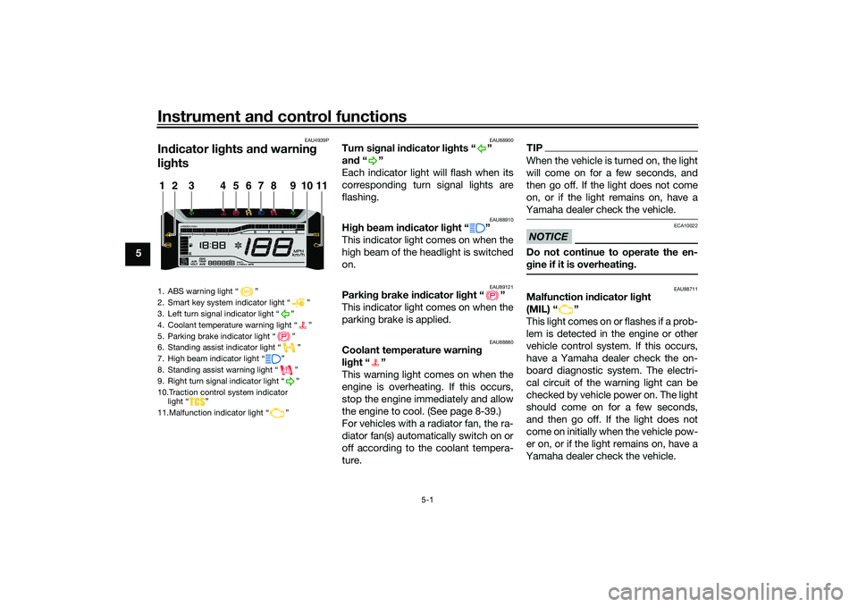
1. ABS warning light “ ”
2. Smart key system indicator light “ ”
3. Left turn signal indicator light “ ”
4. Coolant temperature warning light “ ”
5. Parking brake indicator light “ ”
6. Standing assist indicator light “ ”
7. High beam indicator light “ ”
8. Standing assist warning light “ ”
9. Right turn signal indicator light “ ”
10.Traction control system indicator light “ ”
11.Malfunction indicator light “ ”1
11
2
3
4
5
6
7
8
9
10
UBEDE0E0.book Page 1 Thursday, October 1, 2020 1:04 PM
Page 38 of 112

Instrument and control functions
5-9
5
EAU1234R
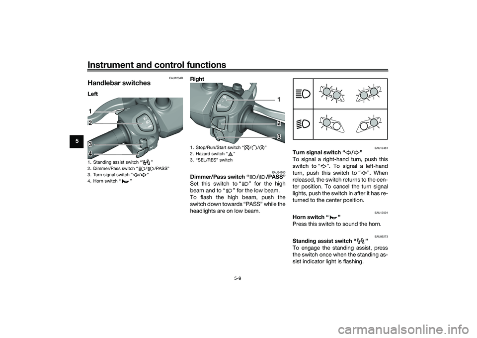
Han dle bar switchesLeft Ri
ght
EAU54203
Dimmer/Pass switch “ / /PASS”
Set this switch to “ ” for the high
beam and to “ ” for the low beam.
To flash the high beam, push the
switch down towards “PASS” while the
headlights are on low beam.
EAU12461
Turn si gnal switch “ / ”
To signal a right-hand turn, push this
switch to “ ”. To signal a left-hand
turn, push this switch to “ ”. When
released, the switch returns to the cen-
ter position. To cancel the turn signal
lights, push the switch in after it has re-
turned to the center position.
EAU12501
Horn switch “ ”
Press this switch to sound the horn.
EAU89273
Stan din g assist switch “ ”
To engage the standing assist, press
the switch once when the standing as-
sist indicator light is flashing.
1. Standing assist switch “ ”
2. Dimmer/Pass switch “ / /PASS”
3. Turn signal switch “ / ”
4. Horn switch “ ”12
3
4
1. Stop/Run/Start switch / / Ž
2. Hazard switch Ž
3.
12
3
UBEDE0E0.book Page 9 Thursday, October 1, 2020 1:04 PM
Page 65 of 112

Periodic maintenance an d a djustment
8-7
8
EAU79370
TIP Engine air filter and V-belt air filter
• This model’s engine air filter is equipped with a disposable oil-coated paper element, which must not be cleaned with compressed air to avoid damaging it.
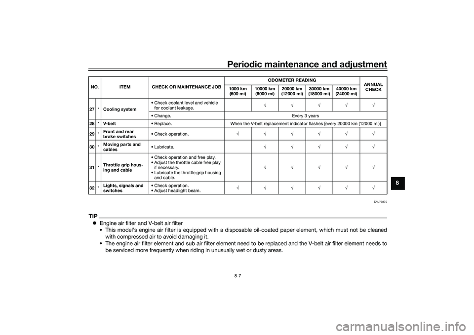
• The engine air filter element and sub air filter element need to be replaced and the V-belt air filter element needs to be serviced more frequently when riding in unusually wet or dusty areas.27 *Coolin g system • Check coolant level and vehicle
for coolant leakage. √√√√√
• Change. Every 3 years
28 *V-belt • Replace. When the V-belt replacement indicator flashes [every 20000 km (12000 mi)]
29 *Front an
d rear
b rake switches • Check operation.
√√√√√√
30 *Movin
g parts an d
ca bles • Lubricate.
√√√√√
31 *Throttle g
rip hous-
in g an d ca ble • Check operation and free play.
• Adjust the throttle cable free play
if necessary.
• Lubricate the throttle grip housing and cable. √√√√√
32 *Li
ghts, si gnals an d
switches • Check operation.
• Adjust headlight beam.
√√√√√√
NO. ITEM CHECK OR MAINTENANCE JOB
ODOMETER READING
ANNUAL
CHECK
1000 km
(600 mi) 10000 km
(6000 mi) 20000 km
(12000 mi) 30000 km
(18000 mi) 40000 km
(24000 mi)
UBEDE0E0.book Page 7 Thursday, October 1, 2020 1:04 PM
Page 109 of 112

12-1
12
Index
AABS....................................................... 5-13
ABS warning light ................................... 5-2
Acceleration and deceleration ................ 7-3
Air filter and V-belt case air filter
elements ............................................. 8-17
Air temperature display .......................... 5-8
Auxiliary DC jack .................................. 5-20BBattery .................................................. 8-32
Brake fluid, changing............................ 8-27
Brake fluid level, checking.................... 8-26
Brake lever, front .................................. 5-10
Brake lever, rear ................................... 5-11
Brake levers, lubricating ....................... 8-28
Brake pedal .......................................... 5-11
Brake pedal, checking and lubricating........................................... 8-29
Braking ................................................... 7-3CCables, checking and lubricating ......... 8-28
Canister ................................................ 8-11
Care ........................................................ 9-1
Catalytic converter ............................... 5-18
Centerstand and sidestand, checking and lubricating ................................... 8-29
Clock ...................................................... 5-5
Coolant ................................................. 8-15
Coolant temperature warning light ......... 5-1DData recording, vehicle......................... 11-2
Diagnostic connector ........................... 11-2
Dimmer/Pass switch............................... 5-9
Display units, switching .......................... 5-4
EEmergency mode ................................. 8-40
Engine break-in ...................................... 7-1
Engine oil and oil filter element ............ 8-12
Engine overheating .............................. 8-39
Engine serial number ........................... 11-1FFinal transmission oil............................ 8-14
Front and rear brake pads, checking ... 8-25
Front brake lever free play, checking ... 8-24
Front fork, checking ............................. 8-30
Fuel ...................................................... 5-16
Fuel consumption, tips for reducing ...... 7-4
Fuel meter .............................................. 5-4
Fuel tank cap........................................ 5-15
Fuel tank overflow hose ....................... 5-18
Fuses, replacing ................................... 8-33HHandlebar switches ............................... 5-9
Hazard switch ...................................... 5-10
High beam indicator light ....................... 5-1
Horn switch ............................................ 5-9IIdentification numbers ......................... 11-1
Ignition circuit cut-off system .............. 5-22
Indicator lights and warning lights ......... 5-1KKey, handling of smart and mechanical keys...................................................... 3-3LLicense plate light bulb, replacing ....... 8-36MMain switch ............................................ 3-7
Maintenance and lubrication, periodic... 8-4 Maintenance, emission control
system .................................................. 8-3
Malfunction indicator light (MIL) ............. 5-1
Matte color, caution................................ 9-1
Model label ........................................... 11-1
Multi-function display ............................. 5-5
Multi-function meter unit ........................ 5-3
OOperating range of the smart key system .................................................. 3-2PPanel, removing and installing ................ 8-9
Parking.................................................... 7-4
Parking brake, checking ....................... 8-25
Parking brake indicator light ................... 5-1
Parking brake lever ............................... 5-12
Part locations.......................................... 2-1RRear brake lever free play, checking .... 8-24SSafe-riding points ................................... 1-5
Safety information................................... 1-1
SEL/RES switch .................................... 5-10
Shock absorber assemblies, adjusting ............................................. 5-20
Sidestand.............................................. 5-21
Smart key................................................ 3-4
Smart key battery, replacing................... 3-6
Smart key system ................................... 3-1
Smart key system indicator light ............ 5-3
Smart key system, troubleshooting ...... 8-37
Spark plug, checking ............................ 8-10
Specifications ....................................... 10-1
Speedometer .......................................... 5-4
UBEDE0E0.book Page 1 Thursday, October 1, 2020 1:04 PM