fuel YAMAHA TRICITY 300 2021 Owners Manual
[x] Cancel search | Manufacturer: YAMAHA, Model Year: 2021, Model line: TRICITY 300, Model: YAMAHA TRICITY 300 2021Pages: 112, PDF Size: 15.18 MB
Page 6 of 112
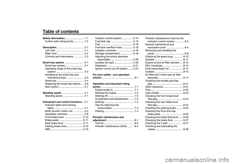
Table of contentsSafety information ............................ 1-1
Further safe-riding points ............... 1-5
Description ....................................... 2-1
Left view ......................................... 2-1
Right view ....................................... 2-2
Controls and instruments ............... 2-3
Smart key system ........................... 3-1
Smart key system ........................... 3-1
Operating range of the smart key system......................................... 3-2
Handling of the smart key and mechanical keys ......................... 3-3
Smart key ....................................... 3-4
Replacing the smart key battery..... 3-6
Main switch .................................... 3-7
Stan din g assist ................................. 4-1
Standing assist ............................... 4-1
Instrument an d control functions ... 5-1
Indicator lights and warning
lights............................................ 5-1
Multi-function meter unit ................ 5-3
Handlebar switches ........................ 5-9
Front brake lever .......................... 5-10
Brake pedal .................................. 5-11
Rear brake lever ........................... 5-11
Parking brake lever ....................... 5-12
ABS .............................................. 5-13 Traction control system ................ 5-14
Fuel tank cap ................................ 5-15
Fuel ............................................... 5-16
Fuel tank overflow hose ................ 5-18
Catalytic converter ........................ 5-18
Storage compartment ................... 5-18
Adjusting the shock absorber
assemblies ................................. 5-20
Auxiliary DC jack ........................... 5-20
Sidestand ...................................... 5-21
Ignition circuit cut-off system ....... 5-22
For your safety – pre-operation
checks ............................................... 6-1
Operation an d important ri din g
points ................................................. 7-1
Engine break-in ............................... 7-1
Starting the engine .......................... 7-2
Starting off ...................................... 7-3
Acceleration and deceleration ........ 7-3
Braking ............................................ 7-3
Tips for reducing fuel consumption ................................ 7-4
Parking ............................................ 7-4
Perio dic maintenance an d
a d justment ........................................ 8-1
Tool kit ............................................ 8-2
Periodic maintenance charts .......... 8-3 Periodic maintenance chart for the
emission control system ............. 8-3
General maintenance and lubrication chart .......................... 8-4
Removing and installing the
panel............................................ 8-9
Checking the spark plug............... 8-10
Canister ........................................ 8-11
Engine oil and oil filter element..... 8-12
Why Yamalube.............................. 8-14
Final transmission oil .................... 8-14
Coolant ......................................... 8-15
Air filter and V-belt case air filter elements .................................... 8-17
Checking the throttle grip free play ............................................ 8-21
Valve clearance............................. 8-21
Tires .............................................. 8-22
Cast wheels .................................. 8-23
Checking the front brake lever
free play..................................... 8-24
Checking the rear brake lever free play..................................... 8-24
Checking the parking brake ......... 8-25
Checking the front and rear brake pads ................................ 8-25
Checking the brake fluid level ...... 8-26
Changing the brake fluid .............. 8-27
Checking the V-belt ...................... 8-27
Checking and lubricating the cables ........................................ 8-28UBEDE0E0.book Page 1 Thursday, October 1, 2020 1:04 PM
Page 15 of 112
Description
2-2
2
EAU10421
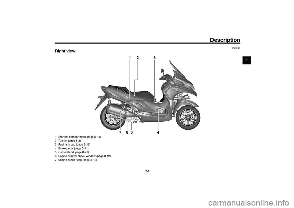
Right view
1
2
3
4
5
6
7
1. Storage compartment (page 5-18)
2. Tool kit (page 8-2)
3. Fuel tank cap (page 5-15)
4. Brake pedal (page 5-11)
5. Centerstand (page 8-29)
6. Engine oil level check window (page 8-12)
7. Engine oil filler cap (page 8-12)
UBEDE0E0.book Page 2 Thursday, October 1, 2020 1:04 PM
Page 20 of 112
Smart key system
3-4
3
Keep the smart key away from
stron g ma gnetic fiel ds an d
ma gnetic o bjects such as key
hol ders, TVs, an d computers.
Keep the smart key away from
electric me dical equipment.
Do not allow oils, polishin g
a g ents, fuel, or any stron g
chemicals to come in contact
with the smart key. The smart
key body may become discol-
ore d or cracked .
TIPThe smart key battery life is ap-
proximately two years, but this
may vary according to operating
conditions.
Replace the smart key battery
when the smart key system indi-
cator light flashes for 20 seconds
when the vehicle is turned on, or
when the smart key indicator light
does not come on when the smart
key button is pushed. (See page
3-6.) After changing the smart key
battery, if the smart key system still does not operate, check the
vehicle battery and then have a
Yamaha dealer check the vehicle.
If the smart key continually re-
ceives radio waves, the smart key
battery will discharge quickly. (For
example, when placed in the vicin-
ity of electrical products such as
televisions, radios, or computers.)
You can register up to six smart
keys for the same vehicle. See a
Yamaha dealer regarding spare
smart keys.
If a smart key is lost, contact a
Yamaha dealer immediately to
prevent the vehicle from being
stolen.
EAU89111
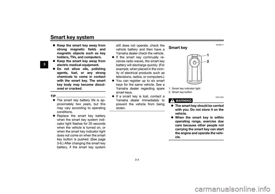
Smart key
WARNING
EWA17952
The smart key shoul d b e carrie d
with you. Do not store it on the
vehicle.
When the smart key is within
operatin g ran ge, exercise due
care because other people not
carryin g the smart key can start
the en gine an d operate the vehi-
cle.1. Smart key indicator light
2. Smart key button
1
2
UBEDE0E0.book Page 4 Thursday, October 1, 2020 1:04 PM
Page 23 of 112
Smart key system
3-7
3
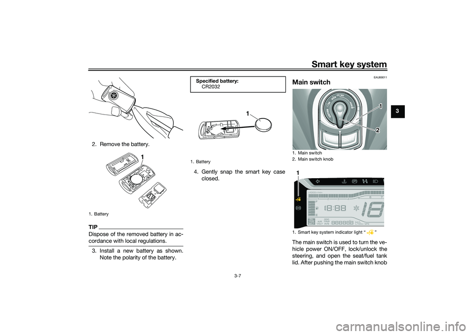
2. Remove the battery.
TIPDispose of the removed battery in ac-
cordance with local regulations.3. Install a new battery as shown. Note the polarity of the battery. 4. Gently snap the smart key case
closed.
EAU89011
Main switchThe main switch is used to turn the ve-
hicle power ON/OFF, lock/unlock the
steering, and open the seat/fuel tank
lid. After pushing the main switch knob
1. Battery
1
Specified b attery:
CR2032
1. Battery
1
1. Main switch
2. Main switch knob
1. Smart key system indicator light Ž
12
1
UBEDE0E0.book Page 7 Thursday, October 1, 2020 1:04 PM
Page 25 of 112
Smart key system
3-9
3
2. The turn signal lights flash once
and the vehicle power turns off.
TIPWhen the main switch is turned to
confirmed (the smart key is either out-
side operation range or has been
turned off), the beeper will sound for 3
seconds and the smart key system in-
dicator light will flash for 30 seconds. During this 30 seconds, the main
switch can be freely operated.
After 30 seconds, the vehicle
power will turn off automatically.
To turn the vehicle power off im-
mediately, push the main switch
knob four times within 2 seconds.
EAU89022
OPEN
Power is supplied to the main switch.
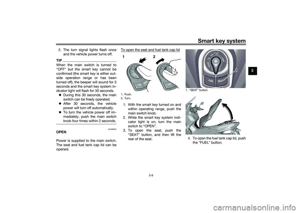
The seat and fuel tank cap lid can be
opened. To open the seat and fuel tank cap lid
1. With the smart key turned on and
within operating range, push the
main switch knob.
2. While the smart key system indi- cator light is on, turn the main
switch to “OPEN”.
3. To open the seat, push the “SEAT” button, and then lift the
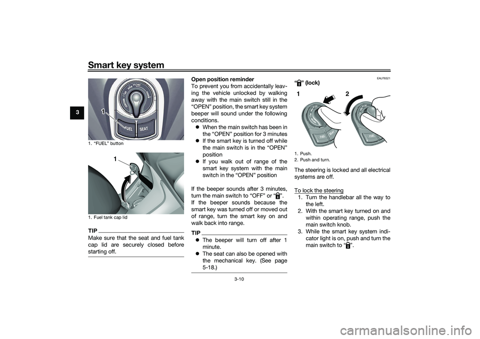
rear of the seat. 4. To open the fuel tank cap lid, push
the “FUEL” button.1. Push.
2. Turn.1 2
1.
1
UBEDE0E0.book Page 9 Thursday, October 1, 2020 1:04 PM
Page 26 of 112
Smart key system
3-10
3
TIPMake sure that the seat and fuel tank
cap lid are securely closed before
starting off.
Open position reminder
To prevent you from accidentally leav-
ing the vehicle unlocked by walking
away with the main switch still in the
“OPEN” position, the smart key system
beeper will sound under the following
conditions. When the main switch has been in
the “OPEN” position for 3 minutes
If the smart key is turned off while
the main switch is in the “OPEN”
position
If you walk out of range of the
smart key system with the main
switch in the “OPEN” position
If the beeper sounds after 3 minutes,
turn the main switch to “OFF” or “ ”.
If the beeper sounds because the
smart key was turned off or moved out
of range, turn the smart key on and
walk back into range.TIP The beeper will turn off after 1
minute.
The seat can also be opened with
the mechanical key. (See page
5-18.)
EAU76521
“” (lock)
The steering is locked and all electrical
systems are off.
To lock the steering1. Turn the handlebar all the way to
the left.
2. With the smart key turned on and within operating range, push the
main switch knob.
3. While the smart key system indi- cator light is on, push and turn the
main switch to “ ”.
1. “FUEL” button
1. Fuel tank cap lid
1
1
1. Push.
2. Push and turn.1 2
UBEDE0E0.book Page 10 Thursday, October 1, 2020 1:04 PM
Page 32 of 112
Instrument and control functions
5-3
5 The indicator light comes on when the
standing assist is engaged.
TIPWhen the vehicle is turned on, the light
will come on for a few seconds, and
then go off. If the light does not come
on, have a Yamaha dealer check the
vehicle.
EAU89262
Stan
din g assist warnin g lig ht “ ”
This warning light comes on if a prob-
lem is detected in the standing assist.
If this occurs, have a Yamaha dealer
check the system.TIP Depending on the problem, the
engine speed may be limited and
the vehicle cannot be driven nor-
mally.
When the vehicle is turned on, the
light will come on for a few sec-
onds, and then go off. If the light
does not come on, or if the light
remains on, have a Yamaha dealer
check the vehicle.
EAU78083
Smart key system in dicator
li g ht “ ”
This indicator light will flash when com-
munication between the vehicle and
smart key takes place and when cer-
tain smart key system operations are
carried out.
The indicator light may also flash when
there is an error in the smart key sys-
tem.TIPWhen the vehicle is turned on, the light
should come on for a few seconds and
then go off. If the light does not come
on, or if the light remains on, have a
Yamaha dealer check the vehicle.
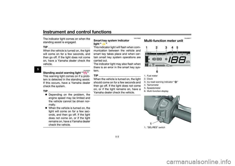
EAU86811
Multi-function meter unit1. Fuel meter
2. Clock
3. Icy road warning indicator “ ”
4. Tachometer
5. Speedometer
6. Multi-function display
1. “SEL/RES” switch1
2
3
4
5
6
1
UBEDE0E0.book Page 3 Thursday, October 1, 2020 1:04 PM
Page 33 of 112
Instrument and control functions
5-4
5
WARNING
EWA12423
Be sure to stop the vehicle before
makin g any settin g chan ges to the
multi-function meter unit. Chang ing
settin gs while ri din g can distract the
operator an d increase the risk of an
acci dent.
EAU89230
Switchin g the display units
The display units can be switched be-
tween kilometers and miles.
To switch the display units1. Turn the vehicle off.
2. While pushing the “SEL” switch, turn the vehicle on.
3. Continue to push the “SEL” switch for at least 5 seconds.
EAU86831
Spee dometer
The speedometer shows the vehicle’s
traveling speed.
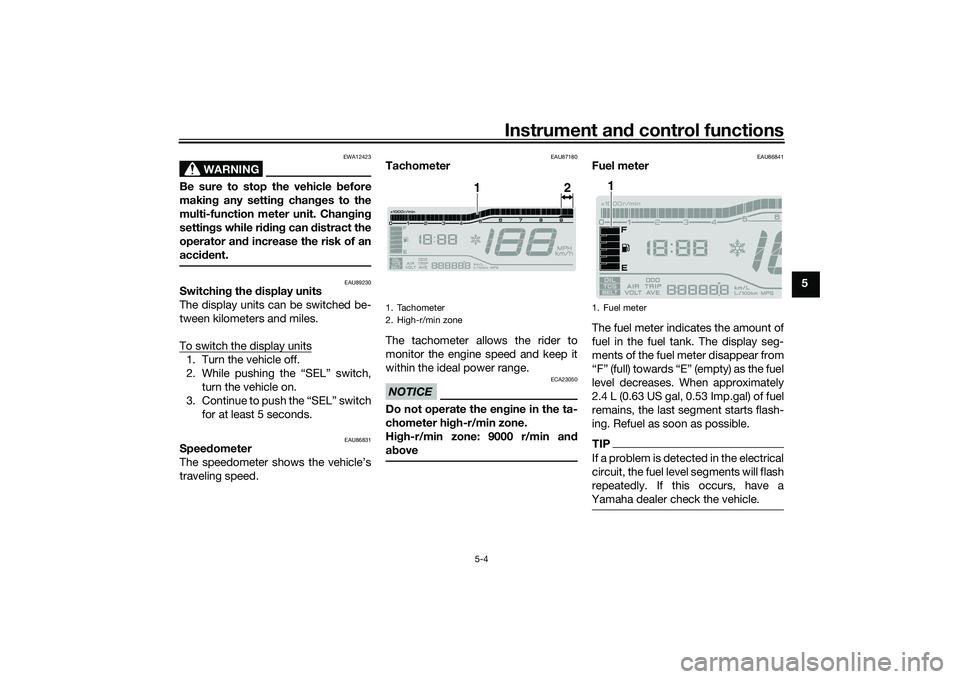
EAU87180
Tachometer
The tachometer allows the rider to
monitor the engine speed and keep it
within the ideal power range.NOTICE
ECA23050
Do not operate the en gine in the ta-
chometer hi gh-r/min zone.
Hi gh-r/min zone: 9000 r/min an d
a b ove
EAU86841
Fuel meter
The fuel meter indicates the amount of
fuel in the fuel tank. The display seg-
ments of the fuel meter disappear from
“F” (full) towards “E” (empty) as the fuel
level decreases. When approximately
2.4 L (0.63 US gal, 0.53 Imp.gal) of fuel
remains, the last segment starts flash-
ing. Refuel as soon as possible.TIPIf a problem is detected in the electrical
circuit, the fuel level segments will flash
repeatedly. If this occurs, have a
Yamaha dealer check the vehicle.
1. Tachometer
2. High-r/min zone
1
2
1. Fuel meter
1
UBEDE0E0.book Page 4 Thursday, October 1, 2020 1:04 PM
Page 34 of 112
Instrument and control functions
5-5
5
EAU89330
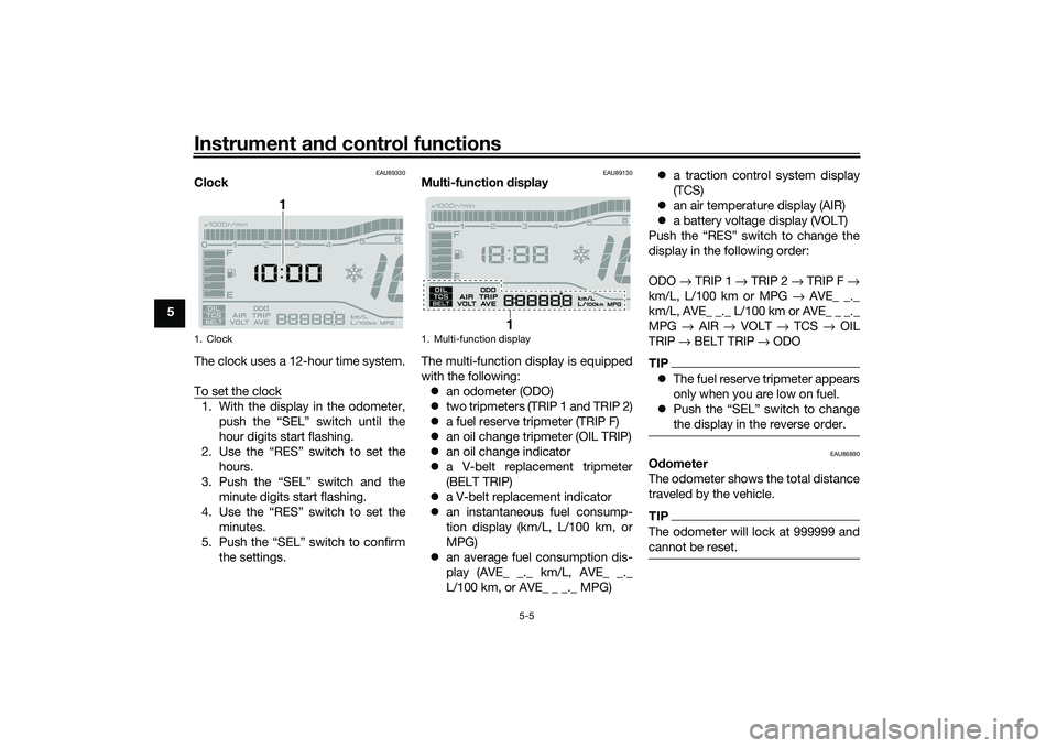
Clock
The clock uses a 12-hour time system.
To set the clock1. With the display in the odometer,
push the “SEL” switch until the
hour digits start flashing.
2. Use the “RES” switch to set the hours.
3. Push the “SEL” switch and the minute digits start flashing.
4. Use the “RES” switch to set the minutes.
5. Push the “SEL” switch to confirm the settings.
EAU89130
Multi-function display
The multi-function display is equipped
with the following: an odometer (ODO)
two tripmeters (TRIP 1 and TRIP 2)
a fuel reserve tripmeter (TRIP F)
an oil change tripmeter (OIL TRIP)
an oil change indicator
a V-belt replacement tripmeter
(BELT TRIP)
a V-belt replacement indicator
an instantaneous fuel consump-
tion display (km/L, L/100 km, or
MPG)
an average fuel consumption dis-
play (AVE_ _._ km/L, AVE_ _._
L/100 km, or AVE_ _ _._ MPG)
a traction control system display
(TCS)
an air temperature display (AIR)
a battery voltage display (VOLT)
Push the “RES” switch to change the
display in the following order:
ODO → TRIP 1 → TRIP 2 → TRIP F →
km/L, L/100 km or MPG → AVE_ _._
km/L, AVE_ _._ L/100 km or AVE_ _ _._
MPG → AIR → VOLT → TCS → OIL
TRIP → BELT TRIP → ODO
TIP The fuel reserve tripmeter appears
only when you are low on fuel.
Push the “SEL” switch to change
the display in the reverse order.
EAU86890
Odometer
The odometer shows the total distance
traveled by the vehicle.TIPThe odometer will lock at 999999 and
cannot be reset.
1. Clock
1
1. Multi-function display
1
UBEDE0E0.book Page 5 Thursday, October 1, 2020 1:04 PM
Page 35 of 112
Instrument and control functions
5-6
5
EAU89140
Tripmeters
The tripmeters show the distance trav-
eled since they were last reset.
To reset a tripmeter, change the dis-
play to the tripmeter you want to reset,
and then push the “RES” switch until it
is reset.TIPThe tripmeters will reset and continue
counting after 9999.9 is reached.
EAU89150
Fuel reserve tripmeter
If the last segment of the fuel meter
starts flashing, the display automati-
cally changes to the fuel reserve trip-
meter “TRIP F” and starts counting the
distance traveled from that point.
To reset the fuel reserve tripmeter,
push the “RES” switch until it is reset.TIPIf you do not reset the fuel reserve trip-
meter manually, it will reset automati-
cally and disappear from the display
after refueling and traveling 5 km (3 mi).
EAU89161
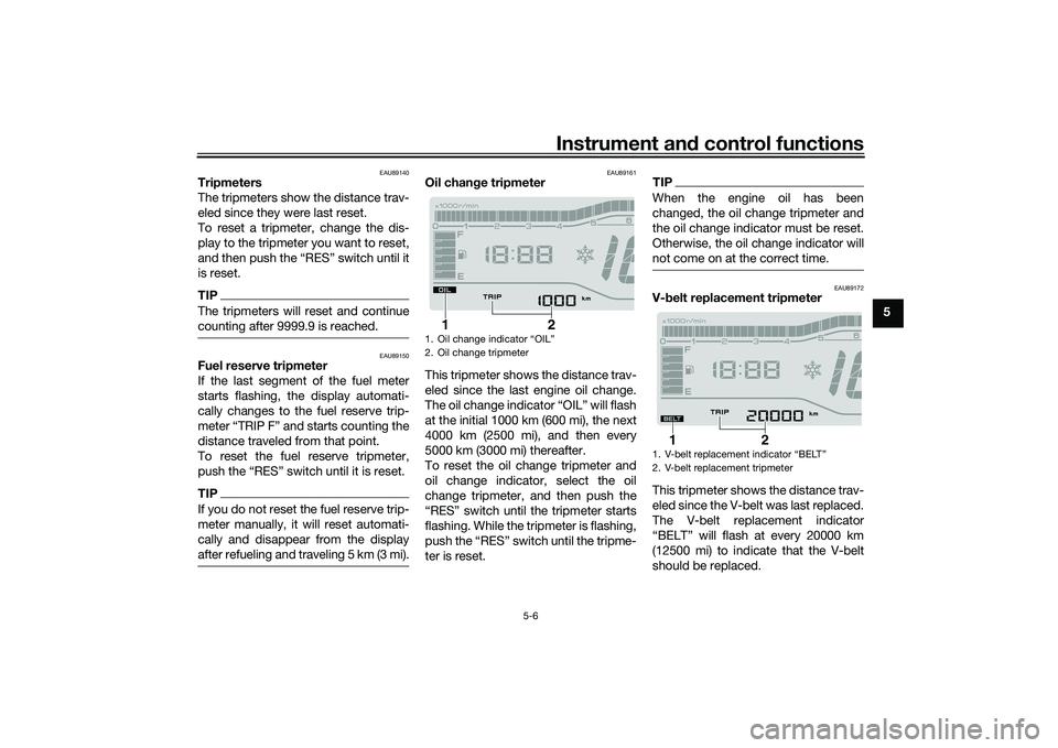
Oil chan ge tripmeter
This tripmeter shows the distance trav-
eled since the last engine oil change.
The oil change indicator “OIL” will flash
at the initial 1000 km (600 mi), the next
4000 km (2500 mi), and then every
5000 km (3000 mi) thereafter.
To reset the oil change tripmeter and
oil change indicator, select the oil
change tripmeter, and then push the
“RES” switch until the tripmeter starts
flashing. While the tripmeter is flashing,
push the “RES” switch until the tripme-
ter is reset.
TIPWhen the engine oil has been
changed, the oil change tripmeter and
the oil change indicator must be reset.
Otherwise, the oil change indicator will
not come on at the correct time.
EAU89172
V- belt replacement tripmeter
This tripmeter shows the distance trav-
eled since the V-belt was last replaced.
The V-belt replacement indicator
“BELT” will flash at every 20000 km
(12500 mi) to indicate that the V-belt
should be replaced.
1. Oil change indicator “OIL”
2. Oil change tripmeter
2
1
1.
2. V-belt replacement tripmeter
2
1
UBEDE0E0.book Page 6 Thursday, October 1, 2020 1:04 PM