YAMAHA TTR125 2004 Manual Online
Manufacturer: YAMAHA, Model Year: 2004, Model line: TTR125, Model: YAMAHA TTR125 2004Pages: 610, PDF Size: 25.85 MB
Page 81 of 610
SPEC
2 - 8
MAINTENANCE SPECIFICATIONS
Cam chain:
Cam chain type/No. of links DID25SD DHA/88 ----
Cam chain adjustment method Automatic ----
Rocker arm/rocker arm shaft:
Shaft outside diameter 9.981 ~ 9.991 mm
(0.3930 ~ 0.3933 in)9.95 mm
(0.3917 in)
Rocker arm inside diameter 10.000 ~ 10.015 mm
(0.3937 ~ 0.3943 in)10.03 mm
(0.3949 in)
Valve, valve seat, valve guide:
Valve clearance (cold) IN 0.08 ~ 0.12 mm
(0.0031 ~ 0.0047 in)----
EX 0.10 ~ 0.14 mm
(0.0039 ~ 0.0055 in)----
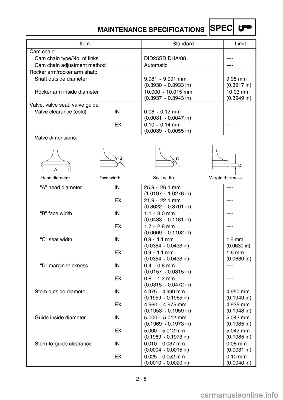
Valve dimensions:
“A” head diameter IN 25.9 ~ 26.1 mm
(1.0197 ~ 1.0276 in)----
EX 21.9 ~ 22.1 mm
(0.8622 ~ 0.8701 in)----
“B” face width IN 1.1 ~ 3.0 mm
(0.0433 ~ 0.1181 in)----
EX 1.7 ~ 2.8 mm
(0.0669 ~ 0.1102 in)----
“C” seat width IN0.9 ~ 1.1 mm
(0.0354 ~ 0.0433 in)1.6 mm
(0.0630 in)
EX 0.9 ~ 1.1 mm
(0.0354 ~ 0.0433 in)1.6 mm
(0.0630 in)
“D” margin thickness IN 0.4 ~ 0.8 mm
(0.0157 ~ 0.0315 in)----
EX 0.8 ~ 1.2 mm
(0.0315 ~ 0.0472 in)----
Stem outside diameter IN4.975 ~ 4.990 mm
(0.1959 ~ 0.1965 in)4.950 mm
(0.1949 in)
EX 4.960 ~ 4.975 mm
(0.1953 ~ 0.1959 in)4.935 mm
(0.1943 in)
Guide inside diameter IN 5.000 ~ 5.012 mm
(0.1969 ~ 0.1973 in)5.042 mm
(0.1985 in)
EX 5.000 ~ 5.012 mm
(0.1969 ~ 0.1973 in)5.042 mm
(0.1985 in)
Stem-to-guide clearance IN0.010 ~ 0.037 mm
(0.0004 ~ 0.0015 in)0.08 mm
(0.0031 in)
EX 0.025 ~ 0.052 mm
(0.0010 ~ 0.0020 in)0.10 mm
(0.0040 in) Item Standard Limit
Head diameter
B
Face widthC
Seat width
D
Margin thicknessA
Page 82 of 610
SPEC
2 - 9
MAINTENANCE SPECIFICATIONS
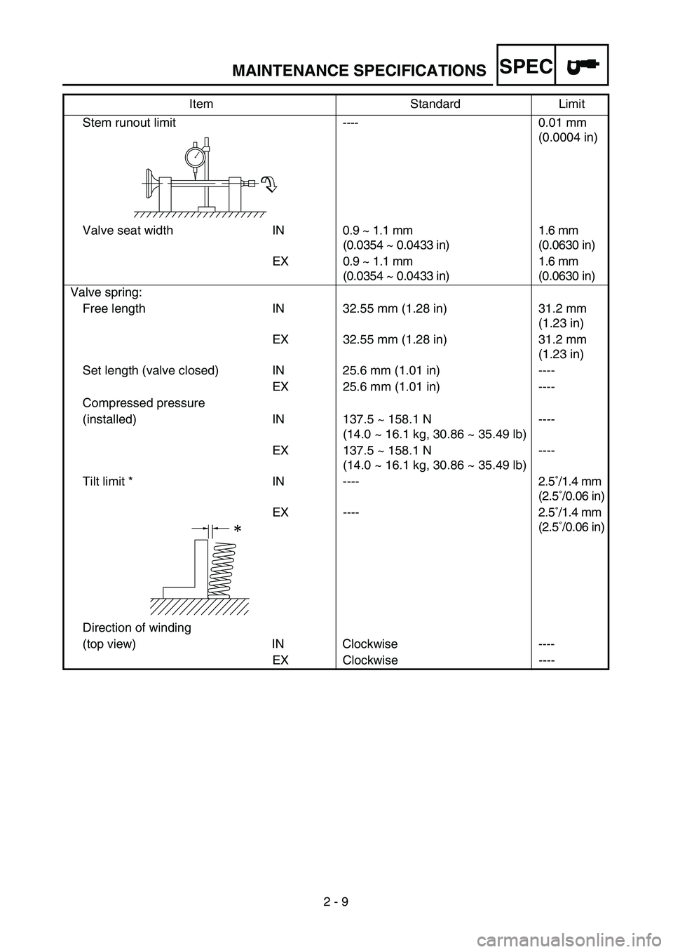
Stem runout limit----0.01 mm
(0.0004 in)
Valve seat width IN0.9 ~ 1.1 mm
(0.0354 ~ 0.0433 in)1.6 mm
(0.0630 in)
EX 0.9 ~ 1.1 mm
(0.0354 ~ 0.0433 in)1.6 mm
(0.0630 in)
Valve spring:
Free length IN 32.55 mm (1.28 in) 31.2 mm
(1.23 in)
EX 32.55 mm (1.28 in) 31.2 mm
(1.23 in)
Set length (valve closed) IN 25.6 mm (1.01 in) ----
EX 25.6 mm (1.01 in) ----
Compressed pressure
(installed) IN 137.5 ~ 158.1 N
(14.0 ~ 16.1 kg, 30.86 ~ 35.49 lb)----
EX 137.5 ~ 158.1 N
(14.0 ~ 16.1 kg, 30.86 ~ 35.49 lb)----
Tilt limit * IN ---- 2.5˚/1.4 mm
(2.5˚/0.06 in)
EX ---- 2.5˚/1.4 mm
(2.5˚/0.06 in)
Direction of winding
(top view) IN Clockwise ----
EX Clockwise ---- Item Standard Limit
Page 83 of 610
SPEC
2 - 10
MAINTENANCE SPECIFICATIONS
Piston:
Piston to cylinder clearance 0.020 ~ 0.026 mm
(0.0008 ~ 0.0010 in)0.15 mm
(0.0059 in)
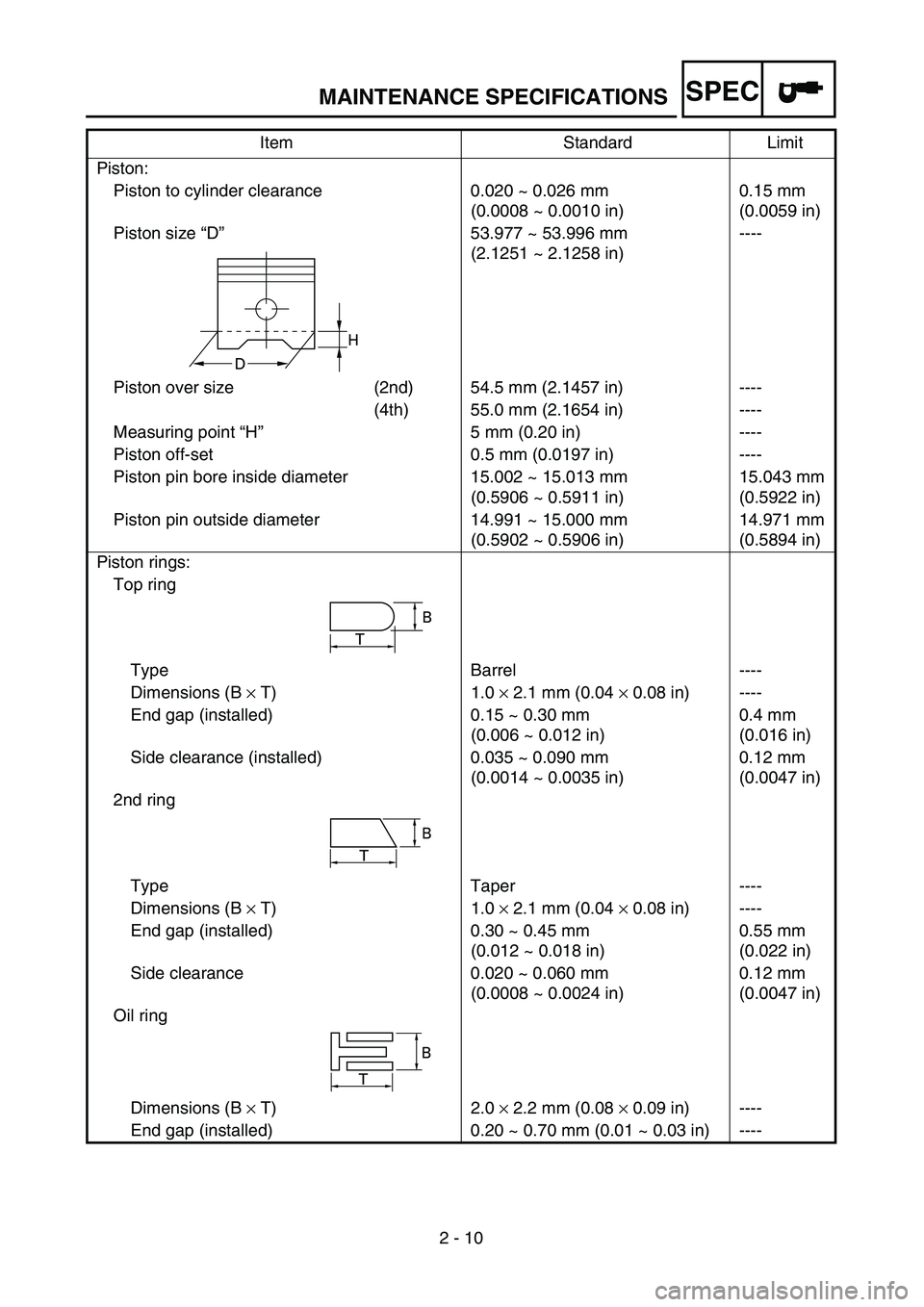
Piston size “D”53.977 ~ 53.996 mm
(2.1251 ~ 2.1258 in)----
Piston over size (2nd) 54.5 mm (2.1457 in) ----
(4th) 55.0 mm (2.1654 in) ----
Measuring point “H”5 mm (0.20 in) ----
Piston off-set 0.5 mm (0.0197 in) ----
Piston pin bore inside diameter 15.002 ~ 15.013 mm
(0.5906 ~ 0.5911 in)15.043 mm
(0.5922 in)
Piston pin outside diameter 14.991 ~ 15.000 mm
(0.5902 ~ 0.5906 in)14.971 mm
(0.5894 in)
Piston rings:
Top ring
Type Barrel ----
Dimensions (B × T) 1.0 × 2.1 mm (0.04 × 0.08 in) ----
End gap (installed) 0.15 ~ 0.30 mm
(0.006 ~ 0.012 in)0.4 mm
(0.016 in)
Side clearance (installed) 0.035 ~ 0.090 mm
(0.0014 ~ 0.0035 in)0.12 mm
(0.0047 in)
2nd ring
Type Taper ----
Dimensions (B × T) 1.0 × 2.1 mm (0.04 × 0.08 in) ----
End gap (installed) 0.30 ~ 0.45 mm
(0.012 ~ 0.018 in)0.55 mm
(0.022 in)
Side clearance 0.020 ~ 0.060 mm
(0.0008 ~ 0.0024 in)0.12 mm
(0.0047 in)
Oil ring
Dimensions (B × T) 2.0 × 2.2 mm (0.08 × 0.09 in) ----
End gap (installed) 0.20 ~ 0.70 mm (0.01 ~ 0.03 in) ----Item Standard Limit
H
D
T
B
B
T
B
T
Page 84 of 610
SPEC
2 - 11
MAINTENANCE SPECIFICATIONS
Crankshaft:
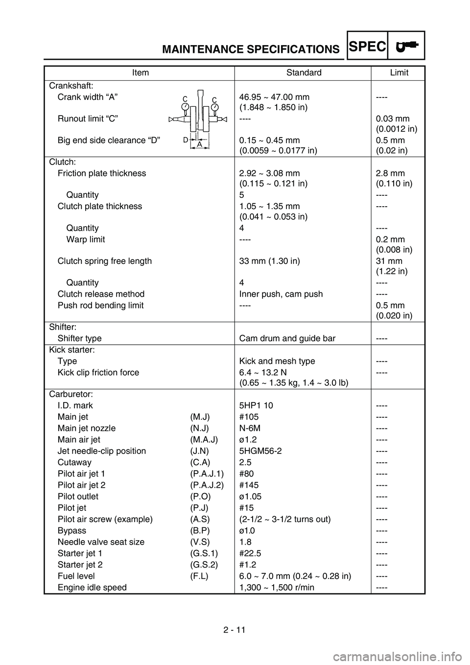
Crank width “A”46.95 ~ 47.00 mm
(1.848 ~ 1.850 in)----
Runout limit “C”---- 0.03 mm
(0.0012 in)
Big end side clearance “D”0.15 ~ 0.45 mm
(0.0059 ~ 0.0177 in)0.5 mm
(0.02 in)
Clutch:
Friction plate thickness 2.92 ~ 3.08 mm
(0.115 ~ 0.121 in)2.8 mm
(0.110 in)
Quantity 5 ----
Clutch plate thickness 1.05 ~ 1.35 mm
(0.041 ~ 0.053 in)----
Quantity 4 ----
Warp limit ---- 0.2 mm
(0.008 in)
Clutch spring free length 33 mm (1.30 in) 31 mm
(1.22 in)
Quantity 4 ----
Clutch release method Inner push, cam push ----
Push rod bending limit ---- 0.5 mm
(0.020 in)
Shifter:
Shifter type Cam drum and guide bar ----
Kick starter:
Type Kick and mesh type ----
Kick clip friction force 6.4 ~ 13.2 N
(0.65 ~ 1.35 kg, 1.4 ~ 3.0 lb)----
Carburetor:
I.D. mark 5HP1 10 ----
Main jet (M.J) #105 ----
Main jet nozzle (N.J) N-6M ----
Main air jet (M.A.J)ø1.2 ----
Jet needle-clip position (J.N) 5HGM56-2 ----
Cutaway (C.A) 2.5 ----
Pilot air jet 1 (P.A.J.1) #80 ----
Pilot air jet 2 (P.A.J.2) #145 ----
Pilot outlet (P.O)ø1.05 ----
Pilot jet (P.J) #15 ----
Pilot air screw (example) (A.S) (2-1/2 ~ 3-1/2 turns out) ----
Bypass (B.P)ø1.0 ----
Needle valve seat size (V.S) 1.8 ----
Starter jet 1 (G.S.1) #22.5 ----
Starter jet 2 (G.S.2) #1.2 ----
Fuel level (F.L) 6.0 ~ 7.0 mm (0.24 ~ 0.28 in) ----
Engine idle speed 1,300 ~ 1,500 r/min ----Item Standard Limit
Page 85 of 610
SPEC
2 - 12
MAINTENANCE SPECIFICATIONS
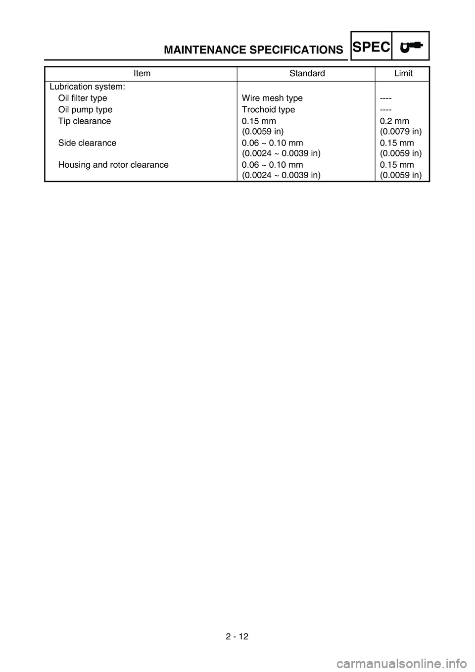
Lubrication system:
Oil filter type Wire mesh type ----
Oil pump type Trochoid type ----
Tip clearance 0.15 mm
(0.0059 in)0.2 mm
(0.0079 in)
Side clearance 0.06 ~ 0.10 mm
(0.0024 ~ 0.0039 in)0.15 mm
(0.0059 in)
Housing and rotor clearance 0.06 ~ 0.10 mm
(0.0024 ~ 0.0039 in)0.15 mm
(0.0059 in) Item Standard Limit
Page 86 of 610
SPEC
2 - 13
MAINTENANCE SPECIFICATIONS
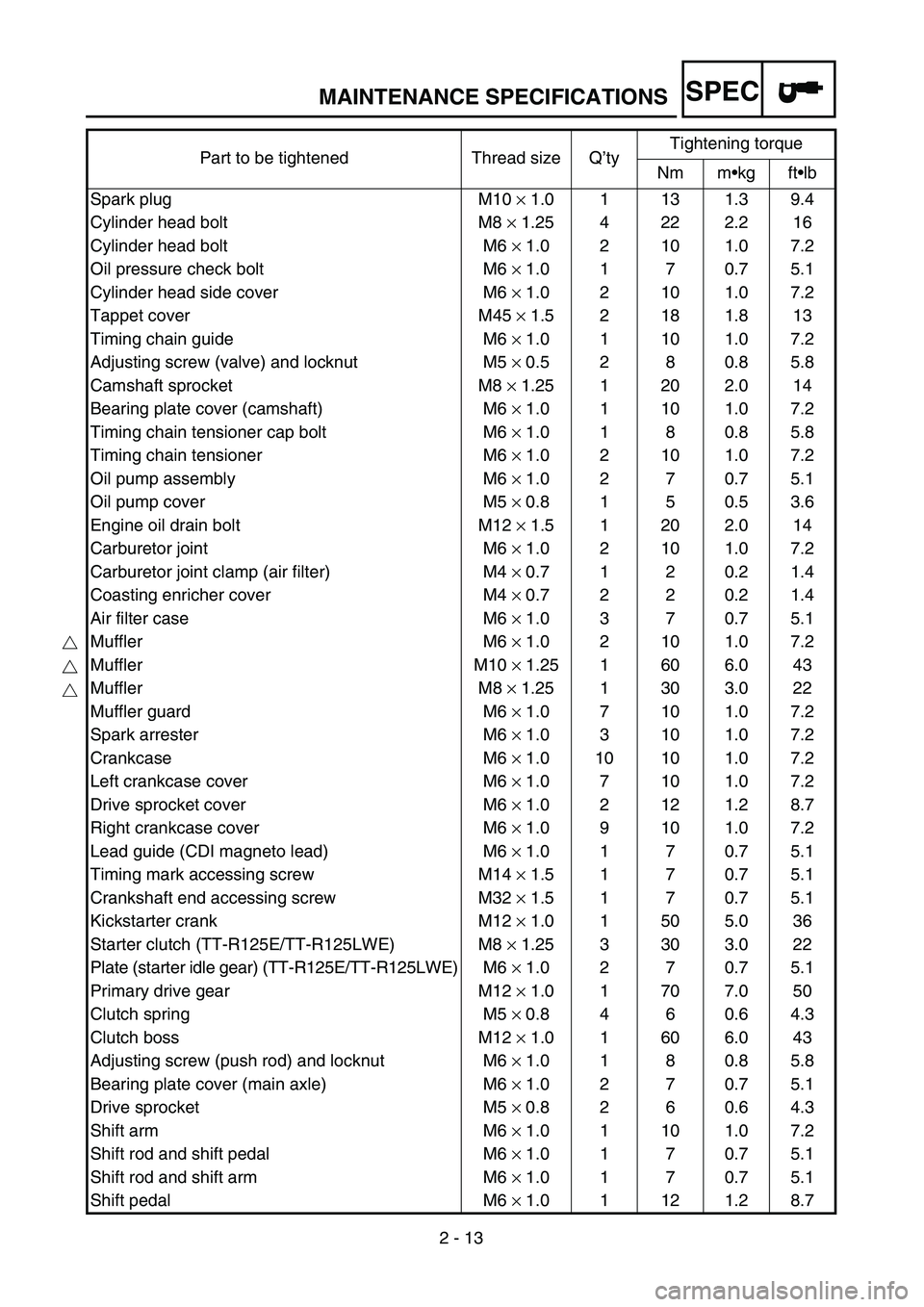
Part to be tightened Thread size Q’tyTightening torque
Nm m•kg ft•lb
Spark plug M10 × 1.0 1 13 1.3 9.4
Cylinder head bolt M8 × 1.25 4 22 2.2 16
Cylinder head bolt M6 × 1.0 2 10 1.0 7.2
Oil pressure check bolt M6 × 1.0 1 7 0.7 5.1
Cylinder head side cover M6 × 1.0 2 10 1.0 7.2
Tappet cover M45 × 1.5 2 18 1.8 13
Timing chain guide M6 × 1.0 1 10 1.0 7.2
Adjusting screw (valve) and locknut M5 × 0.5 2 8 0.8 5.8
Camshaft sprocket M8 × 1.25 1 20 2.0 14
Bearing plate cover (camshaft) M6 × 1.0 1 10 1.0 7.2
Timing chain tensioner cap bolt M6 × 1.0 1 8 0.8 5.8
Timing chain tensioner M6 × 1.0 2 10 1.0 7.2
Oil pump assembly M6 × 1.0 2 7 0.7 5.1
Oil pump cover M5 × 0.8 1 5 0.5 3.6
Engine oil drain bolt M12 × 1.5 1 20 2.0 14
Carburetor joint M6 × 1.0 2 10 1.0 7.2
Carburetor joint clamp (air filter) M4 × 0.7 1 2 0.2 1.4
Coasting enricher cover M4 × 0.7 2 2 0.2 1.4
Air filter case M6 × 1.0 3 7 0.7 5.1
Muffler M6 × 1.0 2 10 1.0 7.2
Muffler M10 × 1.25 1 60 6.0 43
Muffler M8 × 1.25 1 30 3.0 22
Muffler guard M6 × 1.0 7 10 1.0 7.2
Spark arrester M6 × 1.0 3 10 1.0 7.2
Crankcase M6 × 1.0 10 10 1.0 7.2
Left crankcase cover M6 × 1.0 7 10 1.0 7.2
Drive sprocket cover M6 × 1.0 2 12 1.2 8.7
Right crankcase cover M6 × 1.0 9 10 1.0 7.2
Lead guide (CDI magneto lead) M6 × 1.0 1 7 0.7 5.1
Timing mark accessing screw M14 × 1.5 1 7 0.7 5.1
Crankshaft end accessing screw M32 × 1.5 1 7 0.7 5.1
Kickstarter crank M12 × 1.0 1 50 5.0 36
Starter clutch (TT-R125E/TT-R125LWE) M8 × 1.25 3 30 3.0 22
Plate (starter idle gear) (TT-R125E/TT-R125LWE) M6 × 1.0 2 7 0.7 5.1
Primary drive gear M12 × 1.0 1 70 7.0 50
Clutch spring M5 × 0.8 4 6 0.6 4.3
Clutch boss M12 × 1.0 1 60 6.0 43
Adjusting screw (push rod) and locknut M6 × 1.0 1 8 0.8 5.8
Bearing plate cover (main axle) M6 × 1.0 2 7 0.7 5.1
Drive sprocket M5 × 0.8 2 6 0.6 4.3
Shift arm M6 × 1.0 1 10 1.0 7.2
Shift rod and shift pedal M6 × 1.0 1 7 0.7 5.1
Shift rod and shift arm M6 × 1.0 1 7 0.7 5.1
Shift pedal M6 × 1.0 1 12 1.2 8.7
Page 87 of 610
SPEC
2 - 14
MAINTENANCE SPECIFICATIONS
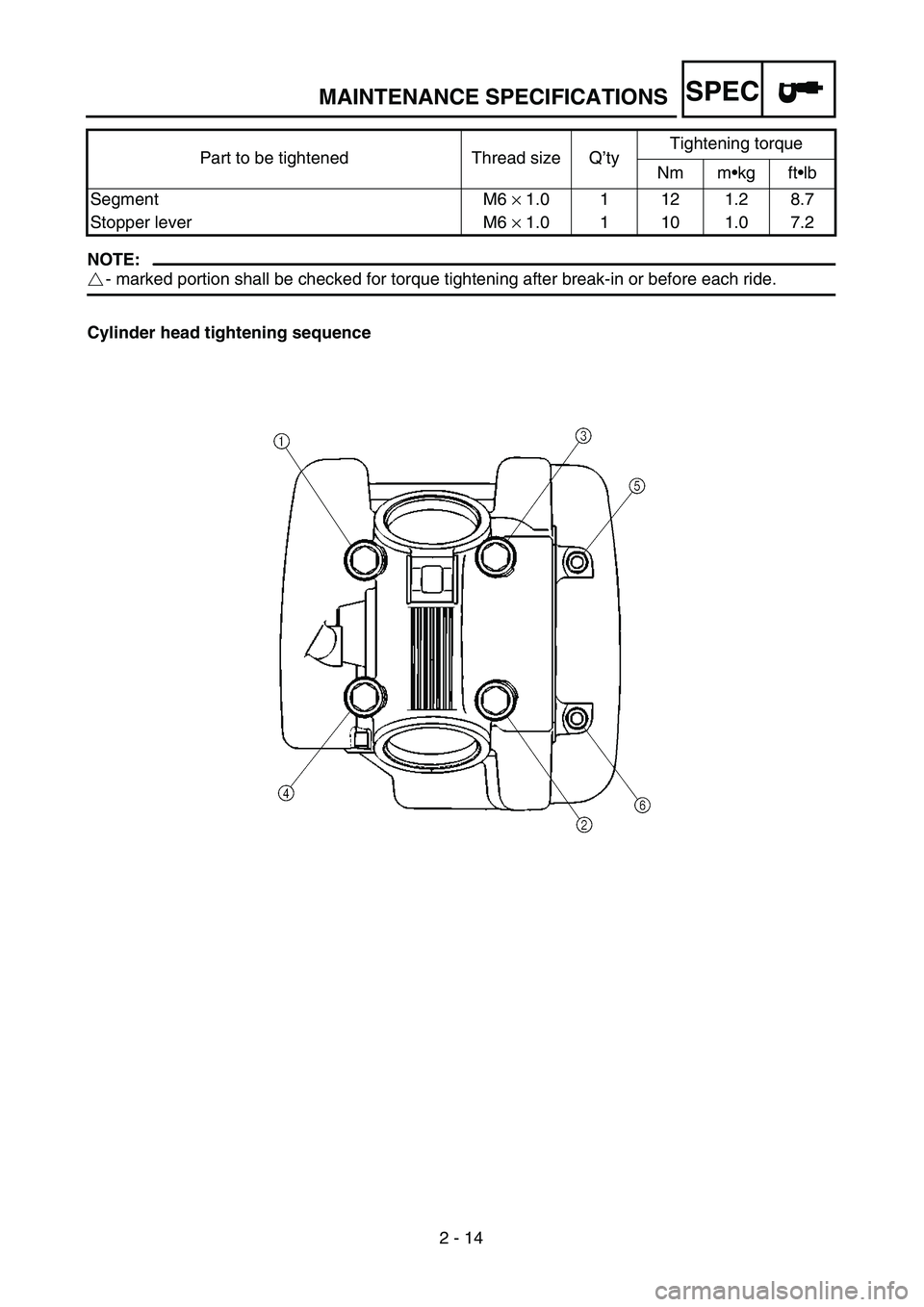
NOTE:
- marked portion shall be checked for torque tightening after break-in or before each ride.
Cylinder head tightening sequenceSegment M6 × 1.0 1 12 1.2 8.7
Stopper lever M6 × 1.0 1 10 1.0 7.2 Part to be tightened Thread size Q’tyTightening torque
Nm m•kg ft•lb
Page 88 of 610
SPEC
2 - 15
MAINTENANCE SPECIFICATIONS
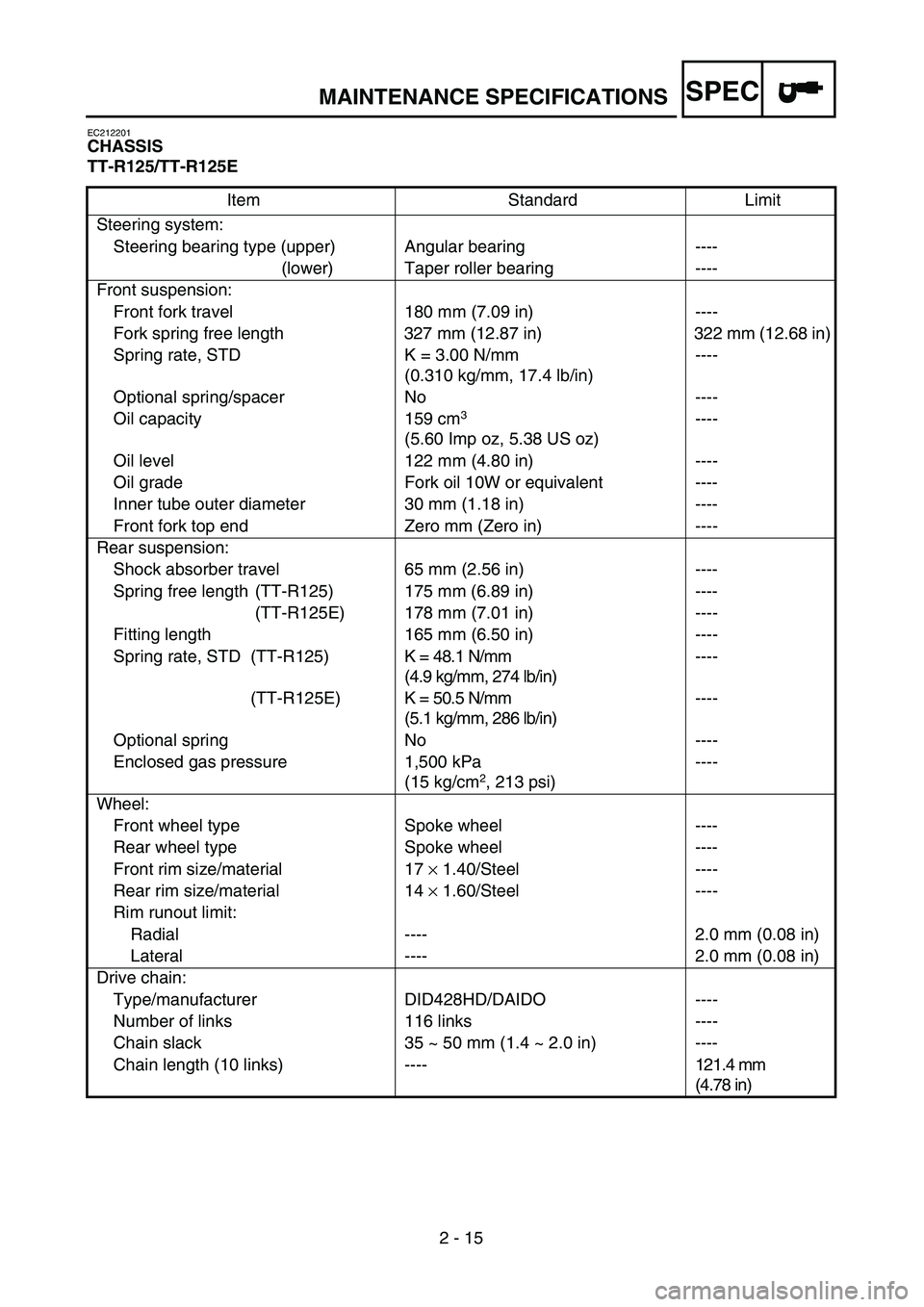
EC212201
CHASSIS
TT-R125/TT-R125E
Item Standard Limit
Steering system:
Steering bearing type (upper) Angular bearing ----
(lower) Taper roller bearing ----
Front suspension:
Front fork travel 180 mm (7.09 in) ----
Fork spring free length 327 mm (12.87 in) 322 mm (12.68 in)
Spring rate, STD K = 3.00 N/mm
(0.310 kg/mm, 17.4 lb/in)----
Optional spring/spacer No ----
Oil capacity 159 cm
3
(5.60 Imp oz, 5.38 US oz)----
Oil level 122 mm (4.80 in) ----
Oil grade Fork oil 10W or equivalent ----
Inner tube outer diameter 30 mm (1.18 in) ----
Front fork top end Zero mm (Zero in) ----
Rear suspension:
Shock absorber travel 65 mm (2.56 in) ----
Spring free length (TT-R125) 175 mm (6.89 in) ----
(TT-R125E) 178 mm (7.01 in) ----
Fitting length 165 mm (6.50 in) ----
Spring rate, STD (TT-R125) K = 48.1 N/mm
(4.9 kg/mm, 274 lb/in)----
(TT-R125E) K = 50.5 N/mm
(5.1 kg/mm, 286 lb/in)----
Optional spring No ----
Enclosed gas pressure 1,500 kPa
(15 kg/cm
2, 213 psi)----
Wheel:
Front wheel type Spoke wheel ----
Rear wheel type Spoke wheel ----
Front rim size/material 17 × 1.40/Steel ----
Rear rim size/material 14 × 1.60/Steel ----
Rim runout limit:
Radial ---- 2.0 mm (0.08 in)
Lateral ---- 2.0 mm (0.08 in)
Drive chain:
Type/manufacturer DID428HD/DAIDO ----
Number of links 116 links ----
Chain slack 35 ~ 50 mm (1.4 ~ 2.0 in) ----
Chain length (10 links) ----121.4 mm
(4.78 in)
Page 89 of 610
SPEC
2 - 16
MAINTENANCE SPECIFICATIONS
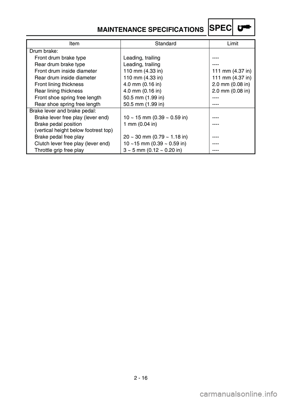
Drum brake:
Front drum brake type Leading, trailing ----
Rear drum brake type Leading, trailing ----
Front drum inside diameter 110 mm (4.33 in) 111 mm (4.37 in)
Rear drum inside diameter 110 mm (4.33 in) 111 mm (4.37 in)
Front lining thickness 4.0 mm (0.16 in) 2.0 mm (0.08 in)
Rear lining thickness 4.0 mm (0.16 in) 2.0 mm (0.08 in)
Front shoe spring free length 50.5 mm (1.99 in) ----
Rear shoe spring free length 50.5 mm (1.99 in) ----
Brake lever and brake pedal:
Brake lever free play (lever end) 10 ~ 15 mm (0.39 ~ 0.59 in) ----
Brake pedal position
(vertical height below footrest top)1 mm (0.04 in) ----
Brake pedal free play 20 ~ 30 mm (0.79 ~ 1.18 in) ----
Clutch lever free play (lever end) 10 ~15 mm (0.39 ~ 0.59 in) ----
Throttle grip free play 3 ~ 5 mm (0.12 ~ 0.20 in) ----Item Standard Limit
Page 90 of 610
SPEC
2 - 17
MAINTENANCE SPECIFICATIONS
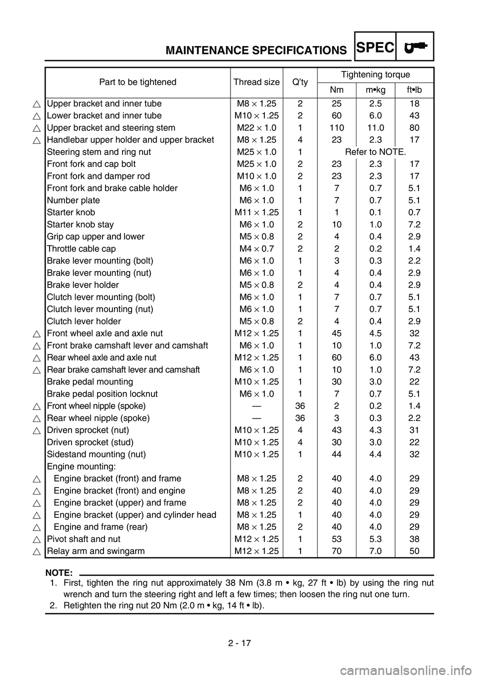
NOTE:
1. First, tighten the ring nut approximately 38 Nm (3.8 m • kg, 27 ft • lb) by using the ring nut
wrench and turn the steering right and left a few times; then loosen the ring nut one turn.
2. Retighten the ring nut 20 Nm (2.0 m • kg, 14 ft • lb). Part to be tightened Thread size Q’tyTightening torque
Nm m•kg ft•lb
Upper bracket and inner tube M8 × 1.25 2 25 2.5 18
Lower bracket and inner tube M10 × 1.25 2 60 6.0 43
Upper bracket and steering stem M22 × 1.0 1 110 11.0 80
Handlebar upper holder and upper bracket M8 × 1.25 4 23 2.3 17
Steering stem and ring nut M25 × 1.0 1 Refer to NOTE.
Front fork and cap bolt M25 × 1.0 2 23 2.3 17
Front fork and damper rod M10 × 1.0 2 23 2.3 17
Front fork and brake cable holder M6 × 1.0 1 7 0.7 5.1
Number plate M6 × 1.0 1 7 0.7 5.1
Starter knob M11 × 1.25 1 1 0.1 0.7
Starter knob stay M6 × 1.0 2 10 1.0 7.2
Grip cap upper and lower M5 × 0.8 2 4 0.4 2.9
Throttle cable cap M4 × 0.7 2 2 0.2 1.4
Brake lever mounting (bolt) M6 × 1.0 1 3 0.3 2.2
Brake lever mounting (nut) M6 × 1.0 1 4 0.4 2.9
Brake lever holder M5 × 0.8 2 4 0.4 2.9
Clutch lever mounting (bolt) M6 × 1.0 1 7 0.7 5.1
Clutch lever mounting (nut) M6 × 1.0 1 7 0.7 5.1
Clutch lever holder M5 × 0.8 2 4 0.4 2.9
Front wheel axle and axle nut M12 × 1.25 1 45 4.5 32
Front brake camshaft lever and camshaft M6 × 1.0 1 10 1.0 7.2
Rear wheel axle and axle nut M12 × 1.25 1 60 6.0 43
Rear brake camshaft lever and camshaft M6 × 1.0 1 10 1.0 7.2
Brake pedal mounting M10 × 1.25 1 30 3.0 22
Brake pedal position locknut M6 × 1.0 1 7 0.7 5.1
Front wheel nipple (spoke)—36 2 0.2 1.4
Rear wheel nipple (spoke)—36 3 0.3 2.2
Driven sprocket (nut) M10 × 1.25 4 43 4.3 31
Driven sprocket (stud) M10 × 1.25 4 30 3.0 22
Sidestand mounting (nut) M10 × 1.25 1 44 4.4 32
Engine mounting:
Engine bracket (front) and frame M8 × 1.25 2 40 4.0 29
Engine bracket (front) and engine M8 × 1.25 2 40 4.0 29
Engine bracket (upper) and frame M8 × 1.25 2 40 4.0 29
Engine bracket (upper) and cylinder head M8 × 1.25 1 40 4.0 29
Engine and frame (rear) M8 × 1.25 2 40 4.0 29
Pivot shaft and nut M12 × 1.25 1 53 5.3 38
Relay arm and swingarm M12 × 1.25 1 70 7.0 50