engine YAMAHA TTR50 2006 Owner's Manual
[x] Cancel search | Manufacturer: YAMAHA, Model Year: 2006, Model line: TTR50, Model: YAMAHA TTR50 2006Pages: 390, PDF Size: 9.69 MB
Page 59 of 390
SPEC
2 - 4
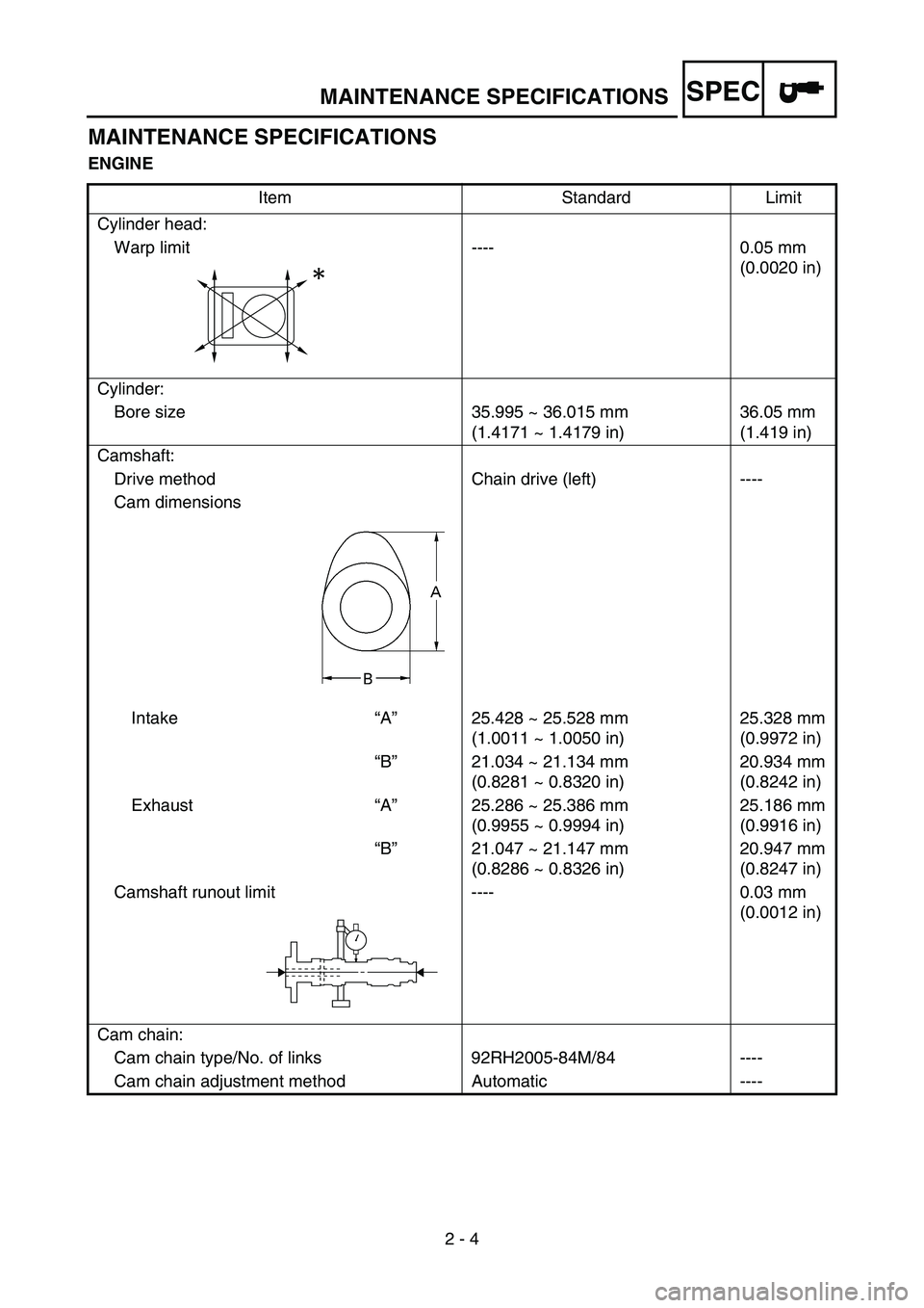
MAINTENANCE SPECIFICATIONS
ENGINEItem Standard Limit
Cylinder head: Warp limit ---- 0.05 mm (0.0020 in)
Cylinder: Bore size 35.995 ~ 36.015 mm (1.4171 ~ 1.4179 in)36.05 mm
(1.419 in)
Camshaft: Drive method Chain drive (left) ----
Cam dimensions
Intake “A ” 25.428 ~ 25.528 mm
(1.0011 ~ 1.0050 in) 25.328 mm
(0.9972 in)
“ B ” 21.034 ~ 21.134 mm
(0.8281 ~ 0.8320 in) 20.934 mm
(0.8242 in)
Exhaust “A ” 25.286 ~ 25.386 mm
(0.9955 ~ 0.9994 in) 25.186 mm
(0.9916 in)
“ B ” 21.047 ~ 21.147 mm
(0.8286 ~ 0.8326 in) 20.947 mm
(0.8247 in)
Camshaft runout limit ---- 0.03 mm (0.0012 in)
Cam chain: Cam chain type/No. of links 92RH2005-84M/84 ----
Cam chain adjustment method Automatic ----
MAINTENANCE SPECIFICATIONS
Page 64 of 390
SPEC
2 - 9
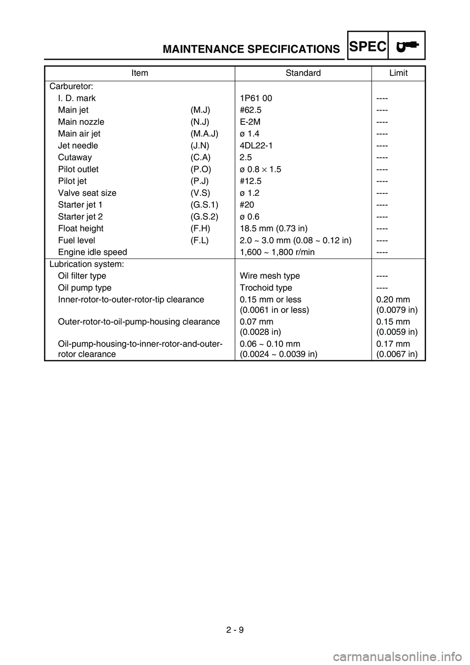
Carburetor:
I. D. mark 1P61 00 ----
Main jet (M.J) #62.5 ----
Main nozzle (N.J) E-2M ----
Main air jet (M.A.J) ø 1.4 ----
Jet needle (J.N) 4DL22-1 ----
Cutaway (C.A) 2.5 ----
Pilot outlet (P.O) ø 0.8 × 1.5 ----
Pilot jet (P.J) #12.5 ----
Valve seat size (V.S) ø 1.2 ----
Starter jet 1 (G.S.1) #20 ----
Starter jet 2 (G.S.2) ø 0.6 ----
Float height (F.H) 18.5 mm (0.73 in) ----
Fuel level (F.L) 2.0 ~ 3.0 mm (0.08 ~ 0.12 in) ----
Engine idle speed 1,600 ~ 1,800 r/min ----
Lubrication system: Oil filter type Wire mesh type ----
Oil pump type Trochoid type ----
Inner-rotor-to-outer-rotor-tip clearance 0.15 mm or less (0.0061 in or less)0.20 mm
(0.0079 in)
Outer-rotor-to-oil-pump-housing clearance 0.07 mm (0.0028 in)0.15 mm
(0.0059 in)
Oil-pump-housing-to-inner-rotor-and-outer-
rotor clearance 0.06 ~ 0.10 mm
(0.0024 ~ 0.0039 in)0.17 mm
(0.0067 in)
Item Standard Limit
MAINTENANCE SPECIFICATIONS
Page 65 of 390
SPEC
2 - 10
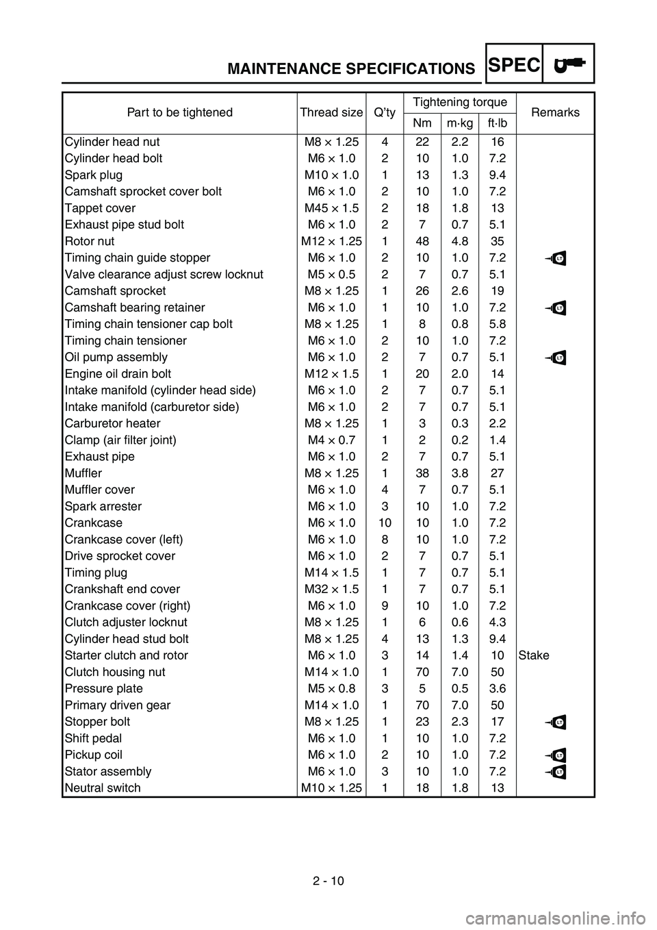
Part to be tightened Thread size Q
’ty Tightening torque
Remarks
Nm m ·kg ft ·lb
Cylinder head nut M8 × 1.25 4 22 2.2 16
Cylinder head bolt M6 × 1.0 2 10 1.0 7.2
Spark plug M10 × 1.0 1 13 1.3 9.4
Camshaft sprocket cover bolt M6 × 1.0 2 10 1.0 7.2
Tappet cover M45 × 1.5 2 18 1.8 13
Exhaust pipe stud bolt M6 × 1.0 2 7 0.7 5.1
Rotor nut M12 × 1.25 1 48 4.8 35
Timing chain guide stopper M6 × 1.0 2 10 1.0 7.2
LT
Valve clearance adjust screw locknut M5 × 0.5 2 7 0.7 5.1
Camshaft sprocket M8 × 1.25 1 26 2.6 19
Camshaft bearing retainer M6 × 1.0 1 10 1.0 7.2
LT
Timing chain tensioner cap bolt M8 × 1.25 1 8 0.8 5.8
Timing chain tensioner M6 × 1.0 2 10 1.0 7.2
Oil pump assembly M6 × 1.0 2 7 0.7 5.1
LT
Engine oil drain bolt M12 × 1.5 1 20 2.0 14
Intake manifold (cylinder head side) M6 × 1.0 2 7 0.7 5.1
Intake manifold (carburetor side) M6 × 1.0 2 7 0.7 5.1
Carburetor heater M8 × 1.25 1 3 0.3 2.2
Clamp (air filter joint) M4 × 0.7 1 2 0.2 1.4
Exhaust pipe M6 × 1.0 2 7 0.7 5.1
Muffler M8 × 1.25 1 38 3.8 27
Muffler cover M6 × 1.0 4 7 0.7 5.1
Spark arrester M6 × 1.0 3 10 1.0 7.2
Crankcase M6 × 1.0 10 10 1.0 7.2
Crankcase cover (left) M6 × 1.0 8 10 1.0 7.2
Drive sprocket cover M6 × 1.0 2 7 0.7 5.1
Timing plug M14 × 1.5 1 7 0.7 5.1
Crankshaft end cover M32 × 1.5 1 7 0.7 5.1
Crankcase cover (right) M6 × 1.0 9 10 1.0 7.2
Clutch adjuster locknut M8 × 1.25 1 6 0.6 4.3
Cylinder head stud bolt M8 × 1.25 4 13 1.3 9.4
Starter clutch and rotor M6 × 1.0 3 14 1.4 10 Stake
Clutch housing nut M14 × 1.0 1 70 7.0 50
Pressure plate M5 × 0.8 3 5 0.5 3.6
Primary driven gear M14 × 1.0 1 70 7.0 50
Stopper bolt M8 × 1.25 1 23 2.3 17
LT
Shift pedal M6 × 1.0 1 10 1.0 7.2
Pickup coil M6 × 1.0 2 10 1.0 7.2
LT
Stator assembly M6 × 1.0 3 10 1.0 7.2LT
Neutral switch M10 × 1.25 1 18 1.8 13
MAINTENANCE SPECIFICATIONS
Page 68 of 390
SPEC
2 - 13
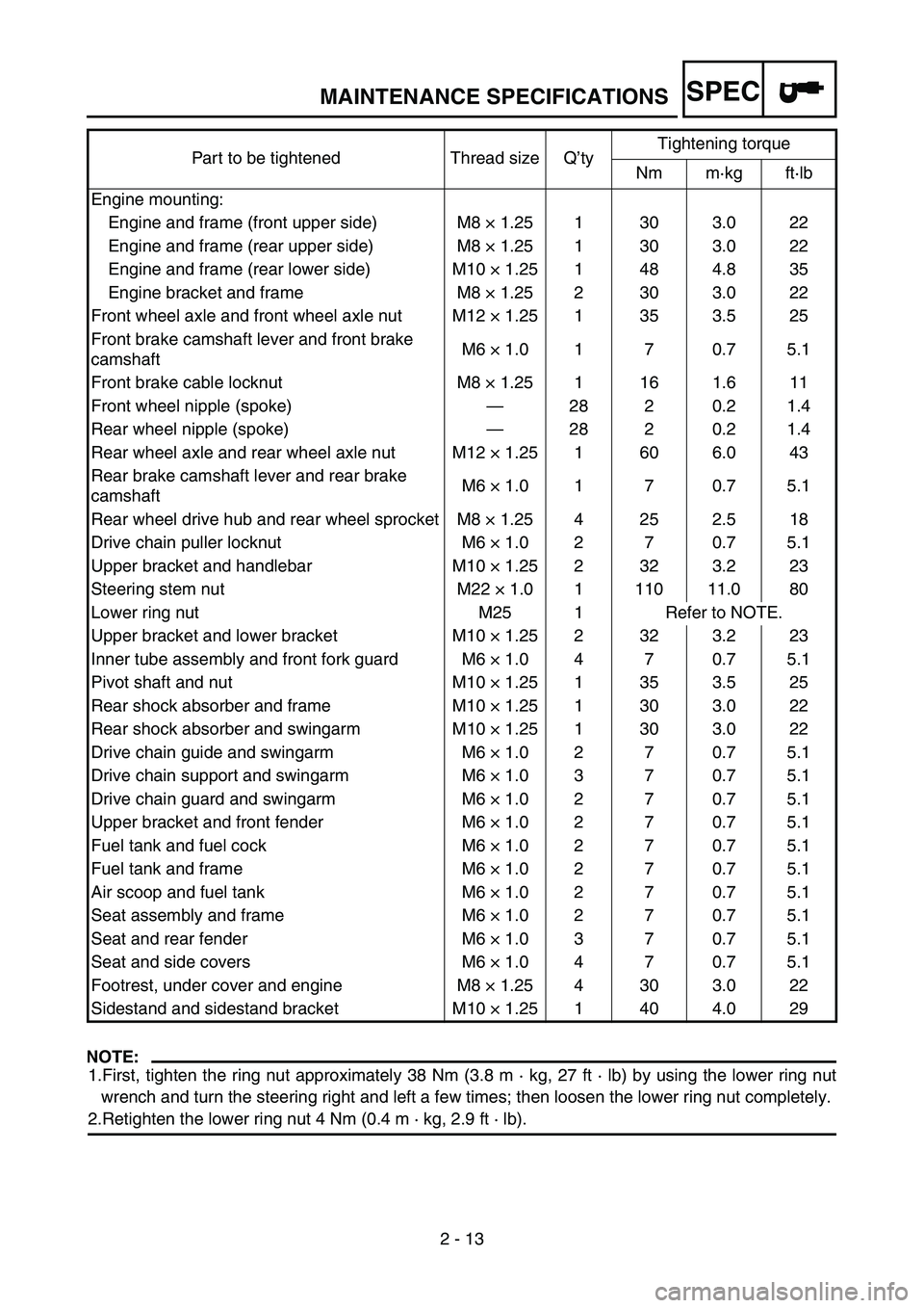
NOTE:
1.First, tighten the ring nut approximately 38 Nm (3.8 m · kg, 27 ft · lb) by using the lower ring nut
wrench and turn the steering right and left a few times; then loosen the lower ring nut completely.
2.Retighten the lower ring nut 4 Nm (0.4 m · kg, 2.9 ft · lb).
Part to be tightened Thread size Q
’ty Tightening torque
Nm m ·kg ft ·lb
Engine mounting: Engine and frame (front upper side) M8 × 1.25 1 30 3.0 22
Engine and frame (rear upper side) M8 × 1.25 1 30 3.0 22
Engine and frame (rear lower side) M10 × 1.25 1 48 4.8 35
Engine bracket and frame M8 × 1.25 2 30 3.0 22
Front wheel axle and front wheel axle nut M12 × 1.25 1 35 3.5 25
Front brake camshaft lever and front brake
camshaft M6
× 1.0 1 7 0.7 5.1
Front brake cable locknut M8 × 1.25 1 16 1.6 11
Front wheel nipple (spoke) —28 2 0.2 1.4
Rear wheel nipple (spoke) —28 2 0.2 1.4
Rear wheel axle and rear wheel axle nut M12 × 1.25 1 60 6.0 43
Rear brake camshaft lever and rear brake
camshaft M6
× 1.0 1 7 0.7 5.1
Rear wheel drive hub and rear wheel sprocket M8 × 1.25 4 25 2.5 18
Drive chain puller locknut M6 × 1.0 2 7 0.7 5.1
Upper bracket and handlebar M10 × 1.25 2 32 3.2 23
Steering stem nut M22 × 1.0 1 110 11.0 80
Lower ring nut M25 1 Refer to NOTE.
Upper bracket and lower bracket M10 × 1.25 2 32 3.2 23
Inner tube assembly and front fork guard M6 × 1.0 4 7 0.7 5.1
Pivot shaft and nut M10 × 1.25 1 35 3.5 25
Rear shock absorber and frame M10 × 1.25 1 30 3.0 22
Rear shock absorber and swingarm M10 × 1.25 1 30 3.0 22
Drive chain guide and swingarm M6 × 1.0 2 7 0.7 5.1
Drive chain support and swingarm M6 × 1.0 3 7 0.7 5.1
Drive chain guard and swingarm M6 × 1.0 2 7 0.7 5.1
Upper bracket and front fender M6 × 1.0 2 7 0.7 5.1
Fuel tank and fuel cock M6 × 1.0 2 7 0.7 5.1
Fuel tank and frame M6 × 1.0 2 7 0.7 5.1
Air scoop and fuel tank M6 × 1.0 2 7 0.7 5.1
Seat assembly and frame M6 × 1.0 2 7 0.7 5.1
Seat and rear fender M6 × 1.0 3 7 0.7 5.1
Seat and side covers M6 × 1.0 4 7 0.7 5.1
Footrest, under cover and engine M8 × 1.25 4 30 3.0 22
Sidestand and sidestand bracket M10 × 1.25 1 40 4.0 29
MAINTENANCE SPECIFICATIONS
Page 71 of 390
SPEC
2 - 16
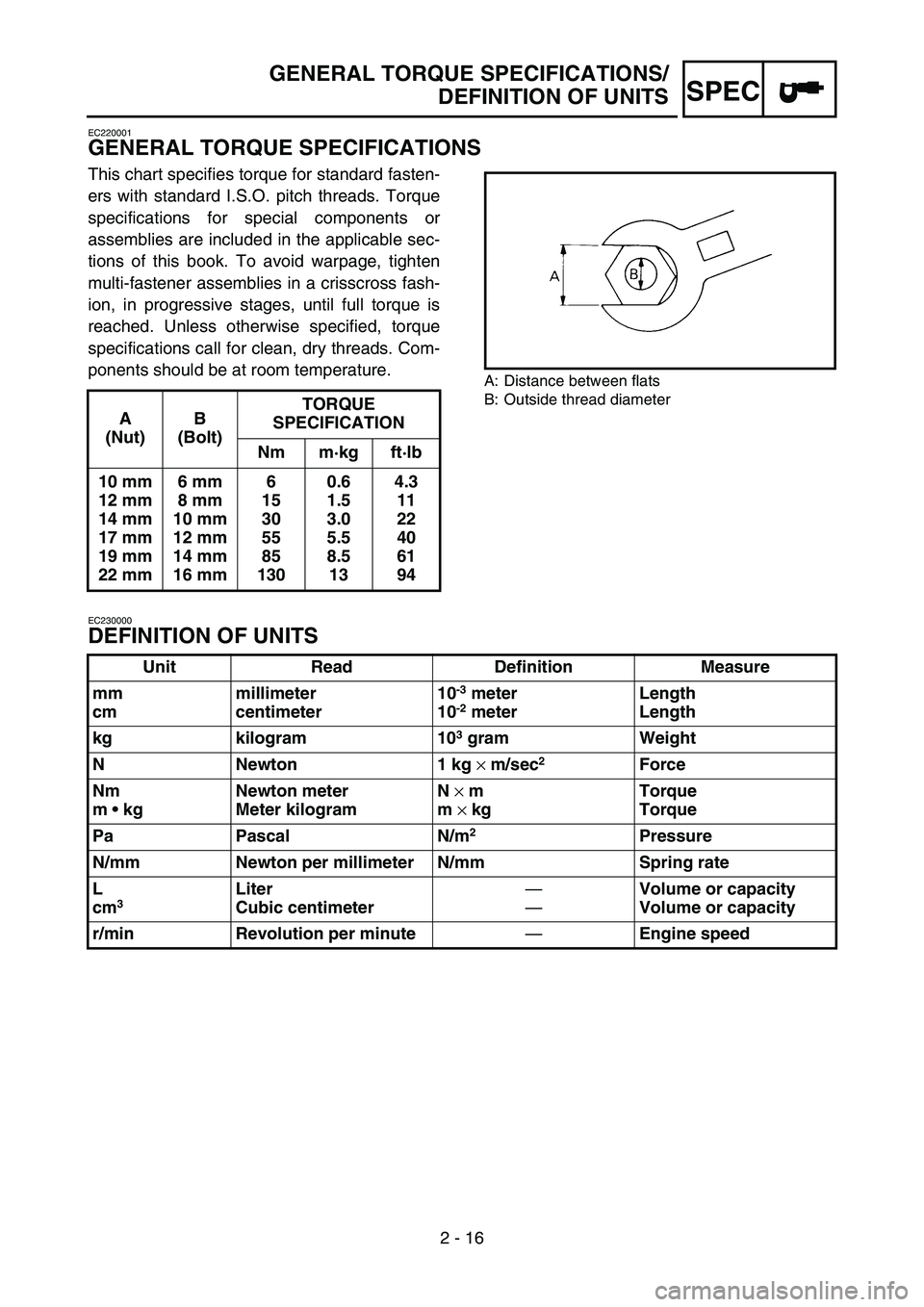
EC220001
GENERAL TORQUE SPECIFICATIONS
This chart specifies torque for standard fasten-
ers with standard I.S.O. pitch threads. Torque
specifications for special components or
assemblies are included in the applicable sec-
tions of this book. To avoid warpage, tighten
multi-fastener assemblies in a crisscross fash-
ion, in progressive stages, until full torque is
reached. Unless otherwise specified, torque
specifications call for clean, dry threads. Com-
ponents should be at room temperature.
A: Distance between flats
B: Outside thread diameter
EC230000
DEFINITION OF UNITS
A
(Nut) B
(Bolt) TORQUE
SPECIFICATION
Nm m ·kg ft ·lb
10 mm
12 mm
14 mm
17 mm
19 mm
22 mm 6 mm
8 mm
10 mm
12 mm
14 mm
16 mm 6
15
30
55
85
130 0.6
1.5
3.0
5.5
8.5
13 4.3
11
22
40
61
94
Unit Read Definition Measure
mm
cm millimeter
centimeter 10
-3 meter
10-2 meter Length
Length
kg kilogram 10
3 gram Weight
N Newton 1 kg × m/sec
2 Force
Nm
m kg Newton meter
Meter kilogram N
× m
m × kg Torque
Torque
Pa Pascal N/m
2Pressure
N/mm Newton per millimeter N/mm Spring rate
L
cm
3 Liter
Cubic centimeter
—
—Volume or capacity
Volume or capacity
r/min Revolution per minute —Engine speed
GENERAL TORQUE SPECIFICATIONS/
DEFINITION OF UNITS
Page 104 of 390

2 - 17
SPECCABLE ROUTING DIAGRAM
CABLE ROUTING DIAGRAM
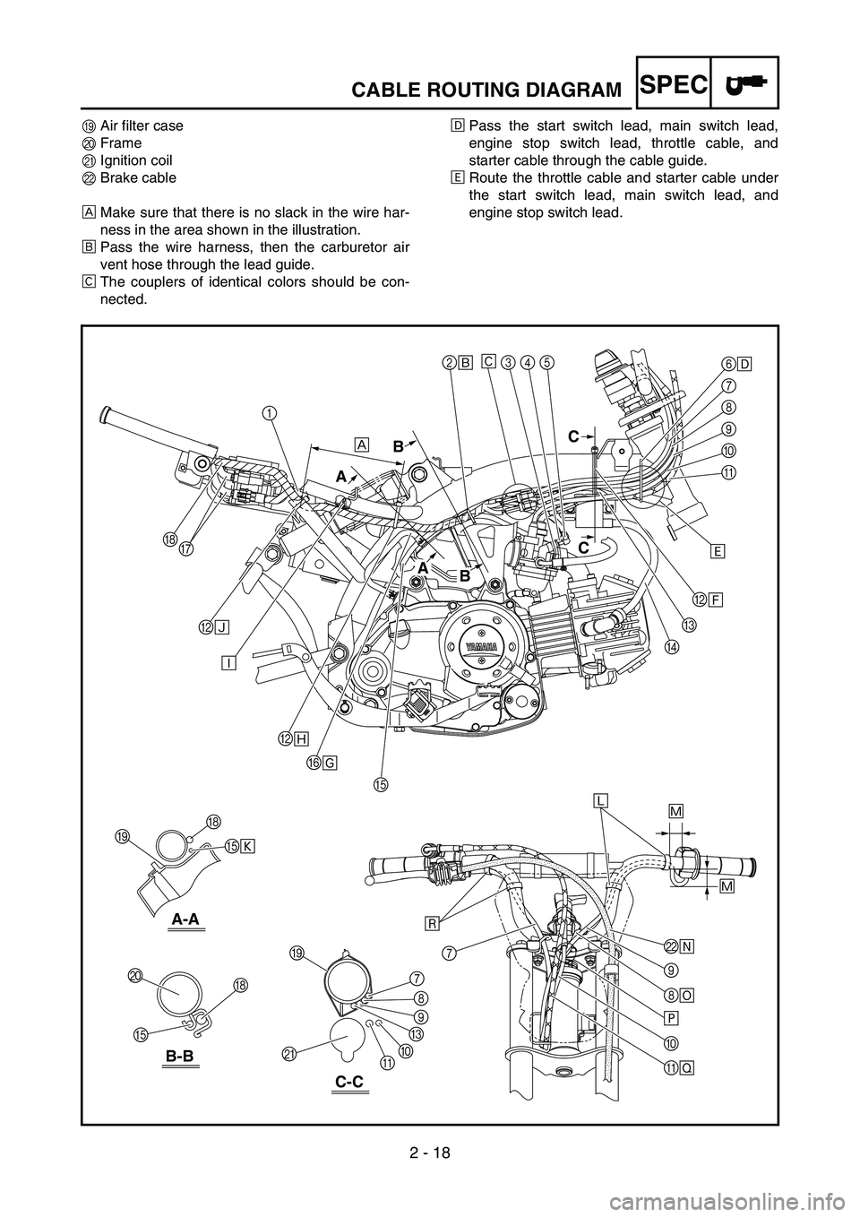
1 CDI unit lead
2 Lead guide
3 Carburetor heater
4 Carburetor heater lead flat terminal
5 Carburetor heater lead L-shaped terminal
6 Cable guide
7 Start switch lead
8 Main switch lead
9 Engine stop switch lead 0
Starter cable
A Throttle cable
B Plastic locking tie
C Thermo switch lead
D Spark plug lead
E Carburetor air vent hose
F Crankcase breather hose
G AC magneto leads
H Wire harness
2
É
BÍ
B Ñ
BÏ
F Î
LÕ
\b
8 \b
×
0
\f Ø
E
E Ò 6
\f
7
8
\b
0
\f
C
D
H
H
7
J
I
I
K 8
7
\b
C
0
\f
E H
G 345
Ê
Ì
Ð
ÙÓ
Ô
Ô
È
B
A C
C
B
A
B-B
A-A
C-C
1
Page 106 of 390
2 - 18
SPECCABLE ROUTING DIAGRAM
IAir filter case
J Frame
K Ignition coil
L Brake cable
È Make sure that there is no slack in the wire har-
ness in the area shown in the illustration.
É Pass the wire harness, then the carburetor air
vent hose through the lead guide.
Ê The couplers of identical colors should be con-
nected. Ë
Pass the start switch lead, main switch lead,
engine stop switch lead, throttle cable, and
starter cable through the cable guide.
Ì Route the throttle cable and starter cable under
the start switch lead, main switch lead, and
engine stop switch lead.
2
É
BÍ
B Ñ
BÏ
F Î
LÕ
\b
8 \b
×
0
\f Ø
E
E Ò 6
\f
7
8
\b
0
\f
C
D
H
H
7
J
I
I
K 8
7
\b
C
0
\f
E H
G 345
Ê
Ì
Ð
ÙÓ
Ô
Ô
È
B
A C
C
B
A
B-B
A-A
C-C
1
Page 108 of 390
2 - 19
SPECCABLE ROUTING DIAGRAM
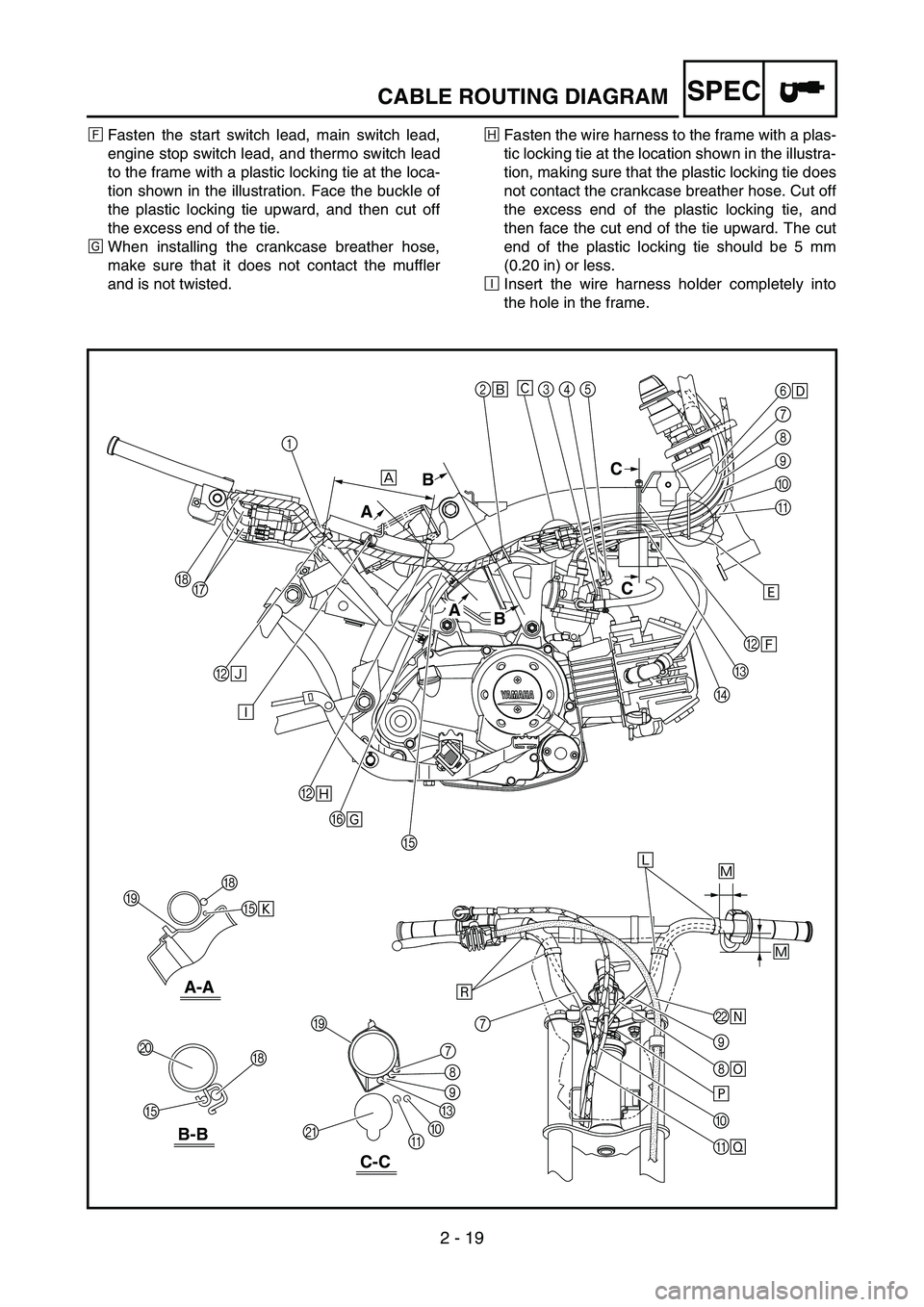
ÍFasten the start switch lead, main switch lead,
engine stop switch lead, and thermo switch lead
to the frame with a plastic locking tie at the loca-
tion shown in the illustration. Face the buckle of
the plastic locking tie upward, and then cut off
the excess end of the tie.
Î When installing the crankcase breather hose,
make sure that it does not contact the muffler
and is not twisted. Ï
Fasten the wire harness to the frame with a plas-
tic locking tie at the location shown in the illustra-
tion, making sure that the plastic locking tie does
not contact the crankcase breather hose. Cut off
the excess end of the plastic locking tie, and
then face the cut end of the tie upward. The cut
end of the plastic locking tie should be 5 mm
(0.20 in) or less.
Ð Insert the wire harness holder completely into
the hole in the frame.
2
É
BÍ
B Ñ
BÏ
F Î
LÕ
\b
8 \b
×
0
\f Ø
E
E Ò 6
\f
7
8
\b
0
\f
C
D
H
H
7
J
I
I
K 8
7
\b
C
0
\f
E H
G 345
Ê
Ì
Ð
ÙÓ
Ô
Ô
È
B
A C
C
B
A
B-B
A-A
C-C
1
Page 110 of 390
2 - 20
SPECCABLE ROUTING DIAGRAM
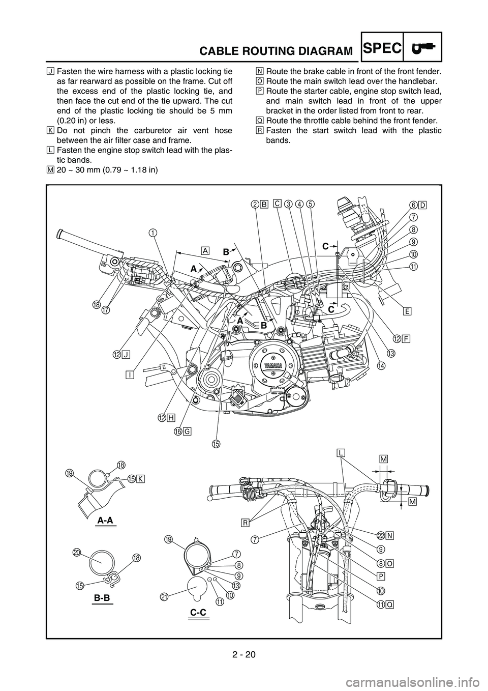
ÑFasten the wire harness with a plastic locking tie
as far rearward as possible on the frame. Cut off
the excess end of the plastic locking tie, and
then face the cut end of the tie upward. The cut
end of the plastic locking tie should be 5 mm
(0.20 in) or less.
Ò Do not pinch the carburetor air vent hose
between the air filter case and frame.
Ó Fasten the engine stop switch lead with the plas-
tic bands.
Ô 20 ~ 30 mm (0.79 ~ 1.18 in) Õ
Route the brake cable in front of the front fender.
Ö Route the main switch lead over the handlebar.
× Route the starter cable, engine stop switch lead,
and main switch lead in front of the upper
bracket in the order listed from front to rear.
Ø Route the throttle cable behind the front fender.
Ù Fasten the start switch lead with the plastic
bands.
2
É
BÍ
B Ñ
BÏ
F Î
LÕ
\b
8 \b
×
0
\f Ø
E
E Ò 6
\f
7
8
\b
0
\f
C
D
H
H
7
J
I
I
K 8
7
\b
C
0
\f
E H
G 345
Ê
Ì
Ð
ÙÓ
Ô
Ô
È
B
A C
C
B
A
B-B
A-A
C-C
1
Page 120 of 390
3 - 1
INSPADJ
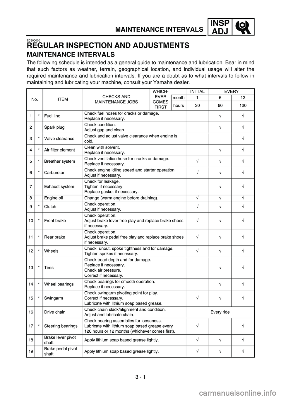
MAINTENANCE INTERVALS
EC300000
REGULAR INSPECTION AND ADJUSTMENTS
MAINTENANCE INTERVALS
The following schedule is intended as a general guide to maintenance and lubrication. Bear in mind
that such factors as weather, terrain, geographical location, and individual usage will alter the
required maintenance and lubrication intervals. If you are a doubt as to what intervals to follow in
maintaining and lubricating your machine, consult your Yamaha dealer.
No. ITEM CHECKS AND
MAINTENANCE JOBS WHICH-
EVER
COMES
FIRST INITIAL EVERY
month 1 6 12
hours 30 60 120
1 * Fuel line Check fuel hoses for cracks or damage.
Replace if necessary.
√
√
2 Spark plug Check condition.
Adjust gap and clean.
√
√
3 * Valve clearance Check and adjust valve clearance when engine is
cold.
√
4 * Air filter element Clean with solvent.
Replace if necessary.
√
√
5 * Breather system Check ventilation hose for cracks or damage.
Replace if necessary.
√
√
√
6 * Carburetor Check engine idling speed and starter operation.
Adjust if necessary.
√
√
√
7 Exhaust system Check for leakage.
Tighten if necessary.
Replace gasket if necessary.
√
√
8 Engine oil Change (warm engine before draining). √
√
√
9 * Clutch Check operation.
Adjust if necessary.
√
√
√
10 * Front brake Check operation.
Adjust brake lever free play and replace brake shoes
if necessary.
√
√
√
11 * Rear brake Check operation.
Adjust brake pedal free play and replace brake shoes
if necessary. √
√
√
12 * Wheels Check runout, spoke tightness and for damage.
Tighten spokes if necessary.
√
√
√
13 * Tires Check tread depth and for damage.
Replace if necessary.
Check air pressure.
Correct if necessary.
√
√
14 * Wheel bearings Check bearings for smooth operation.
Replace if necessary.
√
√
15 * Swingarm Check swingarm pivoting point for play.
Correct if necessary.
Lubricate with lithium soap based grease. √
√
√
16 Drive chain Check chain slack/alignment and condition.
Adjust and lubricate chain. Every ride
17 * Steering bearings Check bearing assemblies for looseness.
Lubricate with lithium soap based grease every
120 hours or 12 months (whichever comes first).
√
√
18 Brake lever pivot
shaft Apply lithium soap based grease lightly.
√
√
√
19 Brake pedal pivot
shaft Apply lithium soap based grease lightly.
√
√
√
3