engine YAMAHA TTR50 2006 Owner's Guide
[x] Cancel search | Manufacturer: YAMAHA, Model Year: 2006, Model line: TTR50, Model: YAMAHA TTR50 2006Pages: 390, PDF Size: 9.69 MB
Page 121 of 390
3 - 2
INSPADJ
MAINTENANCE INTERVALS
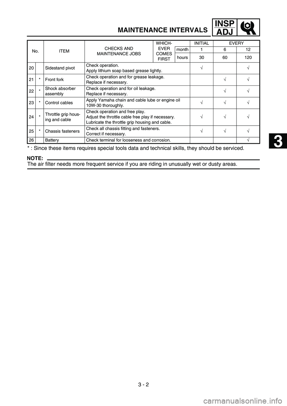
* : Since these items requires special tools data and technical skills, they should be serviced.
NOTE:
The air filter needs more frequent service if you are riding in unusually wet or dusty areas.
20 Sidestand pivot Check operation.
Apply lithium soap based grease lightly.
√
√
21 * Front fork Check operation and for grease leakage.
Replace if necessary.
√
√
22 * Shock absorber
assembly Check operation and for oil leakage.
Replace if necessary.
√
√
23 * Control cables Apply Yamaha chain and cable lube or engine oil
10W-30 thoroughly.
√
√
√
24 * Throttle grip hous-
ing and cable Check operation and free play.
Adjust the throttle cable free play if necessary.
Lubricate the throttle grip housing and cable.
√
√
√
25 * Chassis fasteners Check all chassis fitting and fasteners.
Correct if necessary.
√
√
√
26 Battery Check terminal for looseness and corrosion. √
No. ITEM
CHECKS AND
MAINTENANCE JOBS WHICH-
EVER
COMES FIRST INITIAL EVERY
month 1 6 12
hours 30 60 120
1
2
3
4
5
6
Page 126 of 390
3 - 3
INSPADJ
PRE-OPERATION INSPECTION AND MAINTENANCE
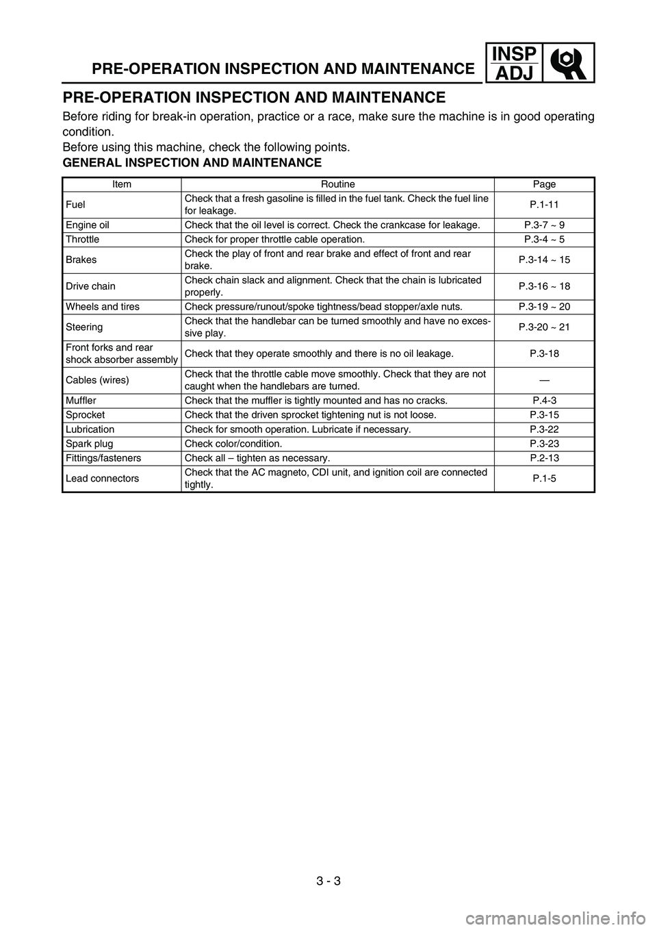
PRE-OPERATION INSPECTION AND MAINTENANCE
Before riding for break-in operation, practice or a race, make sure the machine is in good operating
condition.
Before using this machine, check the following points.
GENERAL INSPECTION AND MAINTENANCE
Item Routine Page
Fuel Check that a fresh gasoline is filled in the fuel tank. Check the fuel line
for leakage. P.1-11
Engine oil Check that the oil level is correct. Check the crankcase for leakage. P.3-7 ~ 9
Throttle Check for proper throttle cable operation. P.3-4 ~ 5
Brakes Check the play of front and rear brake and effect of front and rear
brake. P.3-14 ~ 15
Drive chain Check chain slack and alignment. Check that the chain is lubricated
properly. P.3-16 ~ 18
Wheels and tires Check pressure/runout/spoke tightness/bead stopper/axle nuts. P.3-19 ~ 20
Steering Check that the handlebar can be turned smoothly and have no exces-
sive play. P.3-20 ~ 21
Front forks and rear
shock absorber assembly Check that they operate smoothly and there is no oil leakage. P.3-18
Cables (wires) Check that the throttle cable move smoothly. Check that they are not
caught when the handlebars are turned. —
Muffler Check that the muffler is tightly mounted and has no cracks. P.4-3
Sprocket Check that the driven sprocket tightening nut is not loose. P.3-15
Lubrication Check for smooth operation. Lubricate if necessary. P.3-22
Spark plug Check color/condition. P.3-23
Fittings/fasteners Check all – tighten as necessary. P.2-13
Lead connectors Check that the AC magneto, CDI unit, and ignition coil are connected
tightly. P.1-5
Page 130 of 390

3 - 4
INSPADJ
ENGINE/THROTTLE CABLE ADJUSTMENT
EC350000
ENGINE
THROTTLE CABLE ADJUSTMENT
1. Check:
Throttle grip free play a
Out of specification → Adjust.
Throttle grip free play
a:
3 ~ 5 mm (0.12 ~ 0.20 in)
2. Adjust:
Throttle grip free play
Throttle grip free play adjustment steps:
Carburetor side
NOTE:
Before adjusting the throttle cable free play,
the engine idle speed should be adjusted.
Remove the seat assembly and air scoop
(right).
Refer to “FRONT FENDER, SEAT
ASSEMBLY AND FUEL TANK ” section in
the CHAPTER 4.
Pull back the adjuster cover.
Loosen the locknut 1 on throttle cable.
Turn the adjuster 2 in or out until the
specified free play is obtained.
Turning in b → Free play is increased.
Turning out c → Free play is decreased.
Tighten the locknut.
Slide the adjuster cover to its original posi-
tion.
Install the seat assembly and air scoop
(right).
NOTE:
If the specified throttle cable free play can-
not be obtained on the carburetor side of the
cable, use the adjusting nut on the handle-
bar side.
WARNING
After adjusting, turn the handlebar to
right and left and make sure that the
engine idling does not run faster.
c
b
1
2
Page 132 of 390
3 - 5
INSPADJTHROTTLE CABLE ADJUSTMENT/
SPEED LIMITER ADJUSTMENT
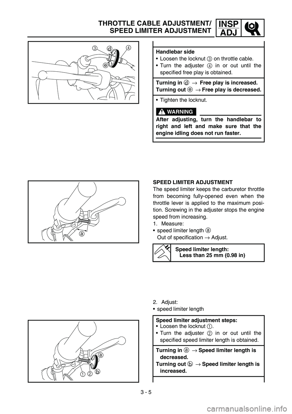
Handlebar side
Loosen the locknut 3 on throttle cable.
Turn the adjuster 4 in or out until the
specified free play is obtained.
Turning in d → Free play is increased.
Turning out e → Free play is decreased.
Tighten the locknut.
WARNING
After adjusting, turn the handlebar to
right and left and make sure that the
engine idling does not run faster.
4
d
e
3
SPEED LIMITER ADJUSTMENT
The speed limiter keeps the carburetor throttle
from becoming fully-opened even when the
throttle lever is applied to the maximum posi-
tion. Screwing in the adjuster stops the engine
speed from increasing.
1. Measure:
speed limiter length a
Out of specification → Adjust.
2. Adjust:
speed limiter length
Speed limiter length:
Less than 25 mm (0.98 in)
Speed limiter adjustment steps:
Loosen the locknut 1.
Turn the adjuster 2 in or out until the
specified speed limiter length is obtained.
Turning in a → Speed limiter length is
decreased.
Turning out b → Speed limiter length is
increased.
a
1 2
a
b
Page 134 of 390
3 - 6
INSPADJ
Tighten the locknut.
WARNING
Particularly for a beginner rider, the
speed limiter should be screwed in
completely. Screw it out little by little as
their riding technique improves. Never
remove the speed limiter for a begin-
ning rider.
For proper throttle lever operation do
not turn out the adjuster more than
25.0 mm (0.98 in). Also, always adjust
the throttle lever free play to 3 ~ 5 mm
(0.12 ~ 0.20 in).
AIR FILTER CLEANING
NOTE:
Proper air filter maintenance is the biggest key
to preventing premature engine wear and
damage.
CAUTION:
Never run the engine without the air filter
element in place; this would allow dirt and
dust to enter the engine and cause rapid
wear and possible engine damage.
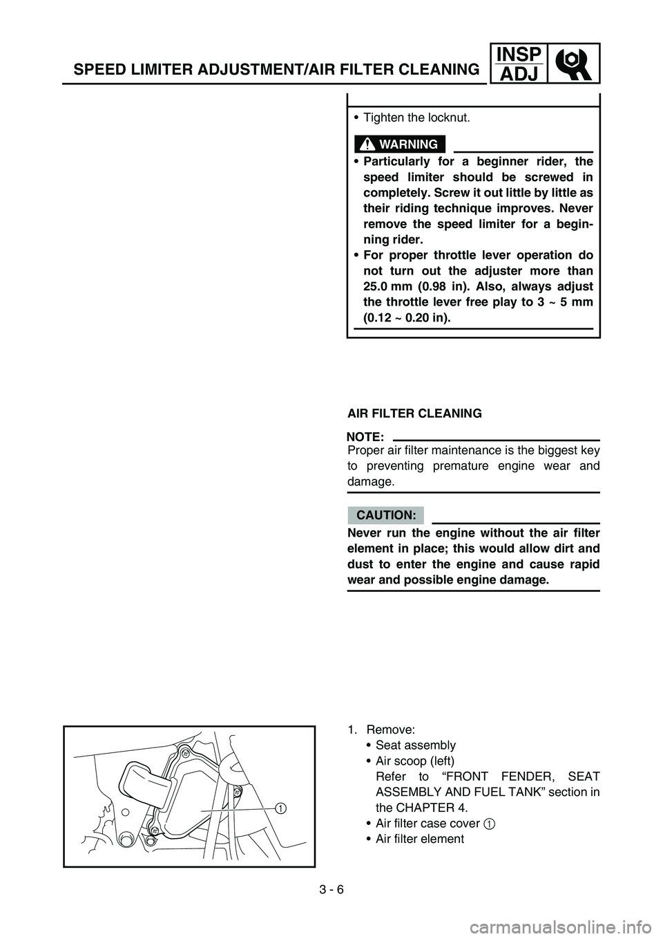
1. Remove: Seat assembly
Air scoop (left)
Refer to “FRONT FENDER, SEAT
ASSEMBLY AND FUEL TANK ” section in
the CHAPTER 4.
Air filter case cover 1
Air filter element
1
SPEED LIMITER ADJUSTMENT/AIR FILTER CLEANING
Page 136 of 390
3 - 7
INSPADJ
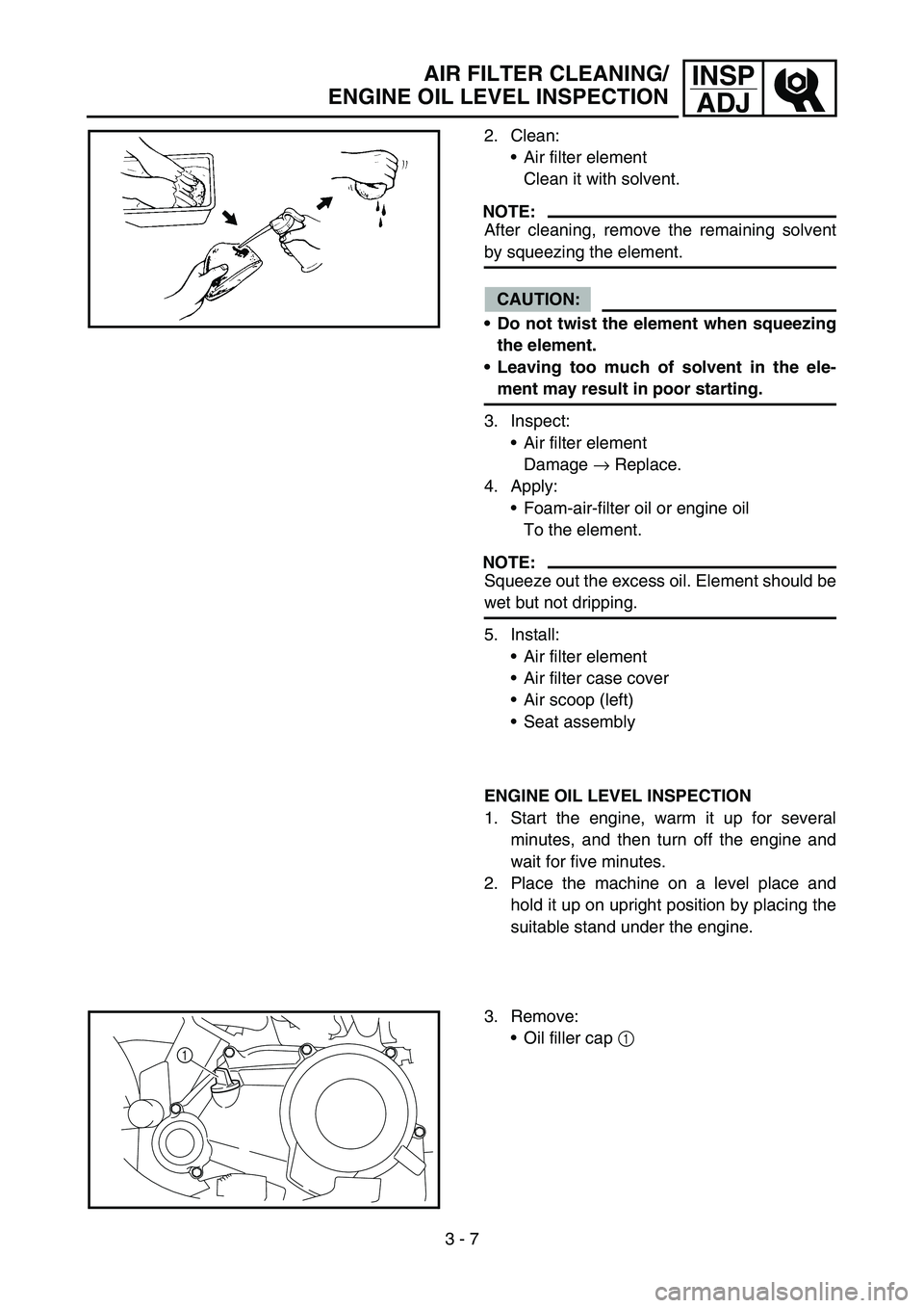
2. Clean:
Air filter element
Clean it with solvent.
NOTE:
After cleaning, remove the remaining solvent
by squeezing the element.
CAUTION:
Do not twist the element when squeezing
the element.
Leaving too much of solvent in the ele-
ment may result in poor starting.
3. Inspect: Air filter element
Damage → Replace.
4. Apply: Foam-air-filter oil or engine oil
To the element.
NOTE:
Squeeze out the excess oil. Element should be
wet but not dripping.
5. Install:
Air filter element
Air filter case cover
Air scoop (left)
Seat assembly
ENGINE OIL LEVEL INSPECTION
1. Start the engine, warm it up for several
minutes, and then turn off the engine and
wait for five minutes.
2. Place the machine on a level place and hold it up on upright position by placing the
suitable stand under the engine.
3. Remove: Oil filler cap 1
1
AIR FILTER CLEANING/
ENGINE OIL LEVEL INSPECTION
Page 138 of 390
3 - 8
INSPADJ
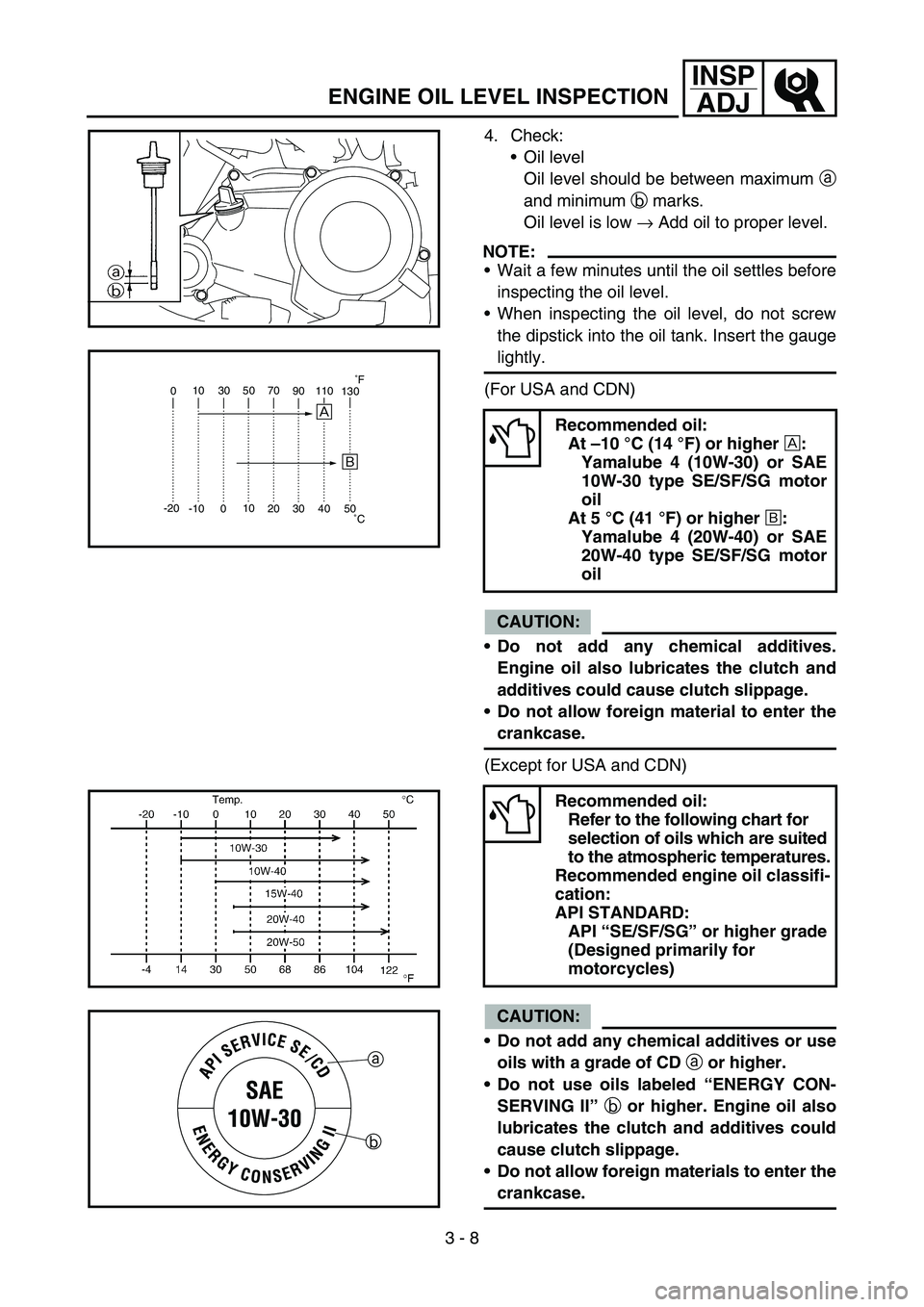
4. Check:
Oil level
Oil level should be between maximum a
and minimum b marks.
Oil level is low → Add oil to proper level.
NOTE:
Wait a few minutes until the oil settles before
inspecting the oil level.
When inspecting the oil level, do not screw
the dipstick into the oil tank. Insert the gauge
lightly.
(For USA and CDN)
CAUTION:
Do not add any chemical additives.
Engine oil also lubricates the clutch and
additives could cause clutch slippage.
Do not allow foreign material to enter the
crankcase.
(Except for USA and CDN)
CAUTION:
Do not add any chemical additives or use
oils with a grade of CD a or higher.
Do not use oils labeled “ENERGY CON-
SERVING II ” b or higher. Engine oil also
lubricates the clutch and additives could
cause clutch slippage.
Do not allow foreign materials to enter the
crankcase.
Recommended oil:
At –10 °C (14 °F) or higher È:
Yamalube 4 (10W-30) or SAE
10W-30 type SE/SF/SG motor
oil
At 5 °C (41 °F) or higher É:
Yamalube 4 (20W-40) or SAE
20W-40 type SE/SF/SG motor
oil
Recommended oil: Refer to the following chart for
selection of oils which are suited
to the atmospheric temperatures.
Recommended engine oil classifi-
cation:
API STANDARD: API “SE/SF/SG ” or higher grade
(Designed primarily for
motorcycles)
0 10 30 50 70
90110
130
-20 -10 010
20 30 40 50
È
É
˚C
˚
F
a
b
ENGINE OIL LEVEL INSPECTION
Page 140 of 390
3 - 9
INSPADJENGINE OIL LEVEL INSPECTION/
ENGINE OIL REPLACEMENT
5. Install:
Oil filler cap
6. Start the engine and let it warm up for sev-
eral minutes.
7. Turn off the engine and inspect the oil level once again.
NOTE:
Wait a few minutes until the oil settles before
inspecting the oil level.
ENGINE OIL REPLACEMENT
1. Start the engine and warm it up for severalminutes, and then turn off the engine and
wait for five minutes.
2. Place the machine on a level place and hold it on upright position by placing the
suitable stand under the engine.
3. Place a suitable container under the engine.
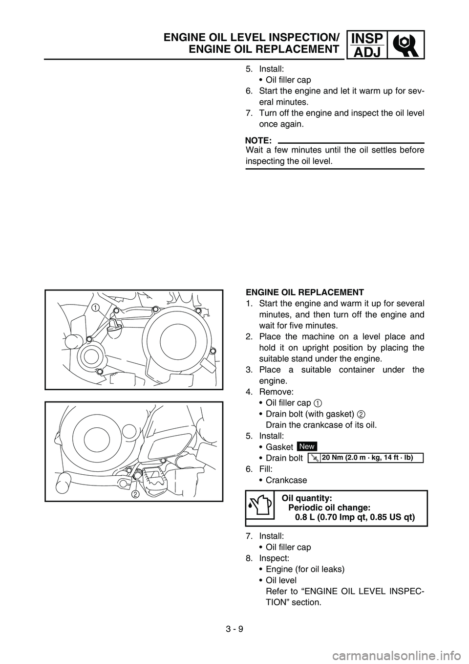
4. Remove:
Oil filler cap 1
Drain bolt (with gasket) 2
Drain the crankcase of its oil.
5. Install: Gasket
Drain bolt
6. Fill: Crankcase
7. Install: Oil filler cap
8. Inspect: Engine (for oil leaks)
Oil level
Refer to “ENGINE OIL LEVEL INSPEC-
TION ” section.
Oil quantity:
Periodic oil change: 0.8 L (0.70 Imp qt, 0.85 US qt)
1
2
New
T R..20 Nm (2.0 m · kg, 14 ft · lb)
Page 142 of 390

3 - 10
INSPADJIDLE SPEED ADJUSTMENT/
VALVE CLEARANCE ADJUSTMENT
IDLE SPEED ADJUSTMENT
1. Start the engine and thoroughly warm it up.
2. Attach:
Tachometer
To spark plug lead.
3. Adjust:
Idle speed
Adjustment steps:
Turn the throttle stop screw 1 until the
engine runs at the lowest possible speed.
To increase idle speed → Turn the throt-
tle stop screw 1 in
a.
To decrease idle speed → Turn the throt-
tle stop screw 1 out
b.
Engine idling speed:
1,600 ~ 1,800 r/min
1
a
b
VALVE CLEARANCE ADJUSTMENT
NOTE:
The valve clearance should be adjusted
when the engine is cool to the touch.
The piston must be at Top Dead Center
(T.D.C.) on compression stroke to check or
adjust the valve clearance.
1. Remove: Spark plug cap 1
Spark plug
Tappet cover (intake side) 2
Tappet cover (exhaust side) 3
Camshaft sprocket cover 4
3
4
1
2
2. Remove:
Timing plug 1
Crankshaft end cover 2
O-rings
1
2
Page 148 of 390
3 - 13
INSPADJVALVE CLEARANCE ADJUSTMENT/
SPARK ARRESTER CLEANING (For USA)
6. Install:
Spark plug
Spark plug cap
Timing plug
Crankshaft end cover
NOTE:
Apply the engine oil on the O-ring.
T R..13 Nm (1.3 m · kg, 9.4 ft · lb)
T R..7 Nm (0.7 m · kg, 5.1 ft · lb)
T R..7 Nm (0.7 m · kg, 5.1 ft · lb)
SPARK ARRESTER CLEANING (For USA)
WARNING
Be sure the exhaust pipe and muffler are
cool before cleaning the spark arrester.
Do not start the engine when cleaning the
exhaust system.
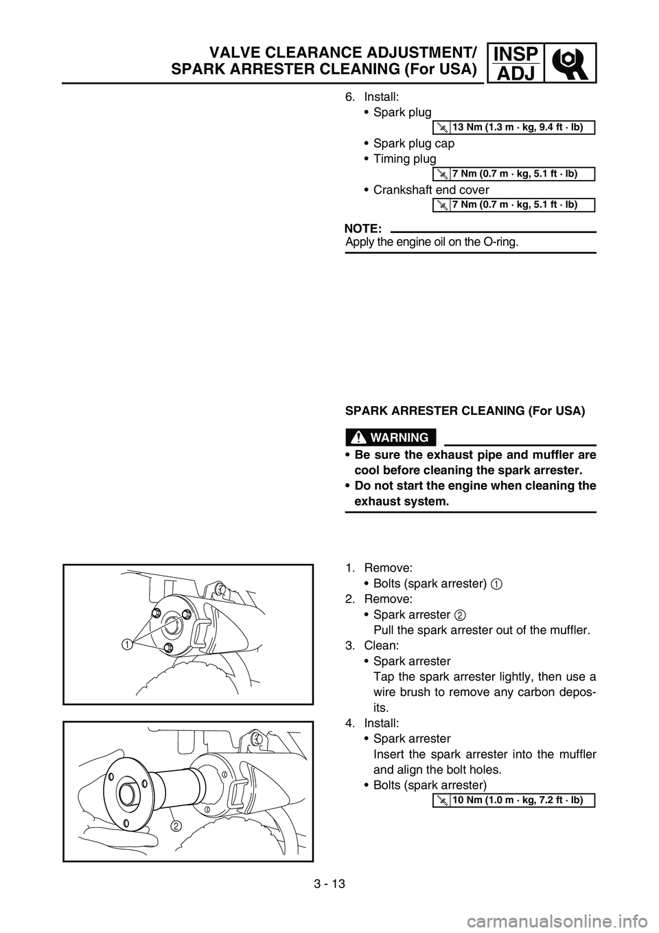
1. Remove: Bolts (spark arrester) 1
2. Remove:
Spark arrester 2
Pull the spark arrester out of the muffler.
3. Clean:
Spark arrester
Tap the spark arrester lightly, then use a
wire brush to remove any carbon depos-
its.
4. Install: Spark arrester
Insert the spark arrester into the muffler
and align the bolt holes.
Bolts (spark arrester)
1
2
T R..10 Nm (1.0 m · kg, 7.2 ft · lb)