engine YAMAHA TTR50 2006 Repair Manual
[x] Cancel search | Manufacturer: YAMAHA, Model Year: 2006, Model line: TTR50, Model: YAMAHA TTR50 2006Pages: 390, PDF Size: 9.69 MB
Page 320 of 390
5 - 10
CHASHANDLEBAR
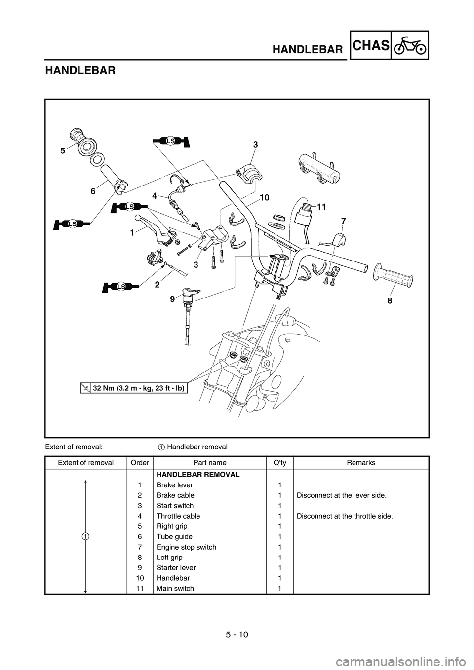
HANDLEBAR
Extent of removal: 1 Handlebar removal
Extent of removal Order Part name Q ’ty Remarks
HANDLEBAR REMOVAL
1Brake lever 1
2 Brake cable 1 Disconnect at the lever side.
3 Start switch 1
4 Throttle cable 1 Disconnect at the throttle side.
5 Right grip 1
6 Tube guide 1
7 Engine stop switch 1
8Left grip 1
9Starter lever 1
10 Handlebar 1
11 Main switch 1
1
Page 324 of 390
5 - 12
CHAS
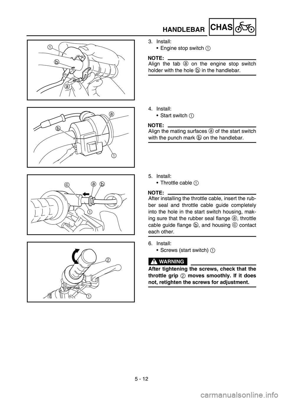
3. Install:Engine stop switch 1
NOTE:
Align the tab a on the engine stop switch
holder with the hole b in the handlebar.
a
b
1
4. Install:
Start switch 1
NOTE:
Align the mating surfaces a of the start switch
with the punch mark b on the handlebar.
1
b a
5. Install:
Throttle cable 1
NOTE:
After installing the throttle cable, insert the rub-
ber seal and throttle cable guide completely
into the hole in the start switch housing, mak-
ing sure that the rubber seal flange a, throttle
cable guide flange b, and housing c contact
each other.
a
c b
1
6. Install:
Screws (start switch) 1
WARNING
After tightening the screws, check that the
throttle grip 2 moves smoothly. If it does
not, retighten the screws for adjustment.
2
1
HANDLEBAR
Page 326 of 390
5 - 13
CHASSTEERING AND FRONT SUSPENSION
EC560000
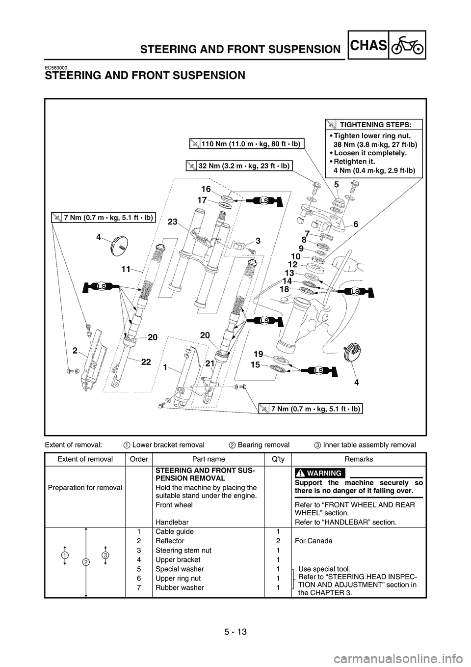
STEERING AND FRONT SUSPENSION
Extent of removal:1 Lower bracket removal
2 Bearing removal
3 Inner table assembly removal
Extent of removal Order Part name Q ’ty Remarks
STEERING AND FRONT SUS-
PENSION REMOVAL
WARNING
Support the machine securely so
there is no danger of it falling over.
Preparation for removal Hold the machine by placing the
suitable stand under the engine.
Front wheel Refer to “FRONT WHEEL AND REAR
WHEEL ” section.
Handlebar Refer to “HANDLEBAR ” section.
1 Cable guide 1
2 Reflector 2 For Canada
3 Steering stem nut 1
4 Upper bracket 1
5 Special washer 1 Use special tool. Refer to “STEERING HEAD INSPEC-
TION AND ADJUSTMENT ” section in
the CHAPTER 3.
6 Upper ring nut 1
7 Rubber washer 1
213
Page 334 of 390
5 - 17
CHASSWINGARM
EC570000
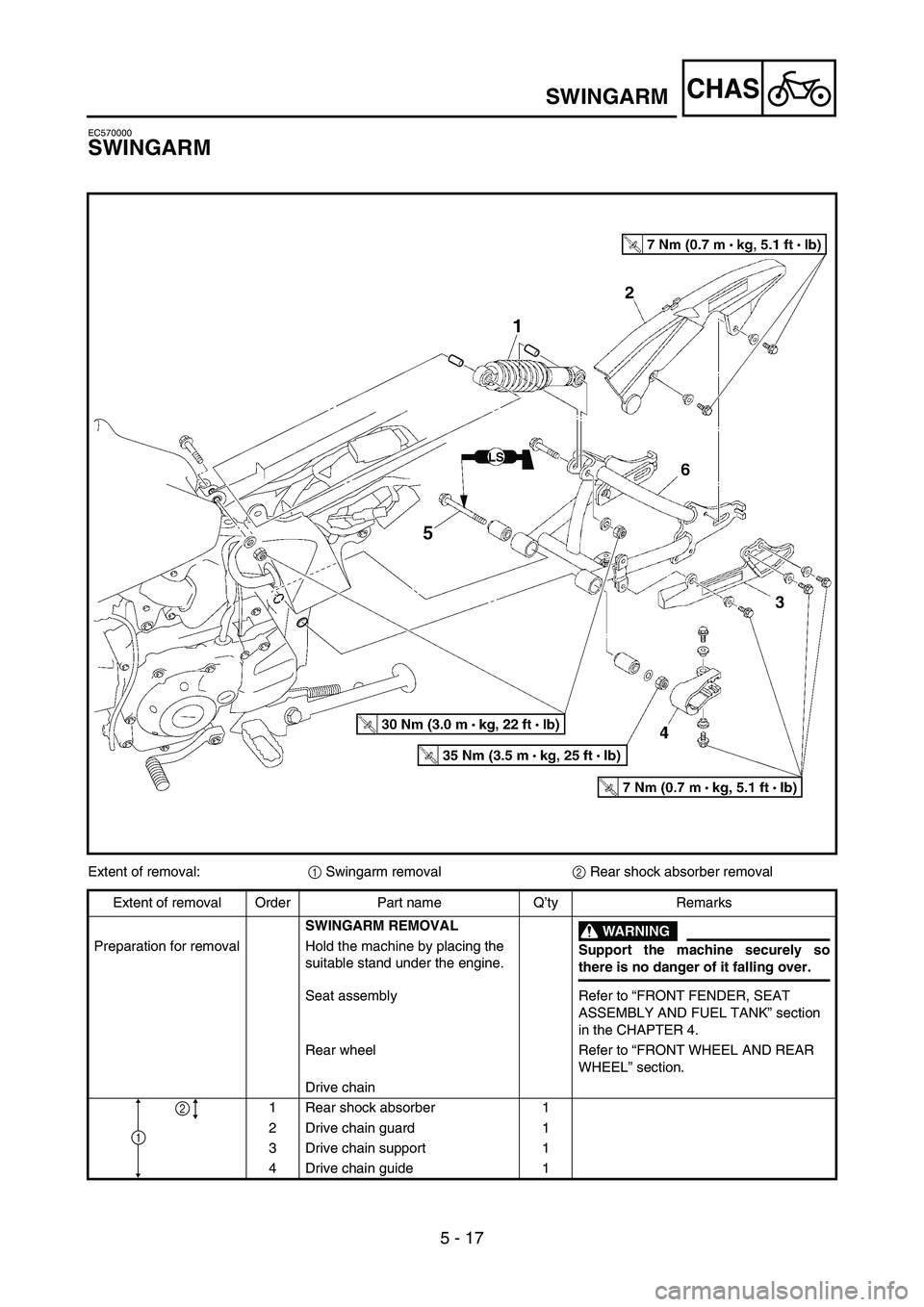
SWINGARM
Extent of removal:1 Swingarm removal
2 Rear shock absorber removal
Extent of removal Order Part name Q ’ty Remarks
SWINGARM REMOVAL
WARNING
Support the machine securely so
there is no danger of it falling over.
Preparation for removal Hold the machine by placing the
suitable stand under the engine.
Seat assembly Refer to “FRONT FENDER, SEAT
ASSEMBLY AND FUEL TANK ” section
in the CHAPTER 4.
Rear wheel Refer to “FRONT WHEEL AND REAR
WHEEL ” section.
Drive chain
1 Rear shock absorber 1
2 Drive chain guard 1
3 Drive chain support 1
4 Drive chain guide 1
1
2
Page 340 of 390

6 - 1
–+ELEC
345
6
78
\b0
B\f
2
1
ELECTRICAL COMPONENTS AND WIRING DIAGRAM
EC600000
ELECTRICAL
EC610000
ELECTRICAL COMPONENTS AND WIRING DIAGRAM
EC611000
ELECTRICAL COMPONENTS
1 Thermo switch
2 Main switch
3 Engine stop switch
4 Ignition coil
5 Ground lead
6 Fuse
7 Battery
8 CDI unit
9 Starter relay 0
Rectifier/regulator
A Neutral switch
B AC magneto
C Carburetor heater
D Start switch
E Spark plug
F Starter motorCOLOR CODE
B ...................... Black
Br .................... Brown
O ..................... Orange
R ..................... Red
Sb .................... Sky blue
W ..................... White
Y ...................... Yellow
EC612000
WIRING DIAGRAM
R
WR
W
BL /WSb B
RW
W
W
OO
B
B
Y /R
R
W
B
R
Y /RY /R
Y
ON
OFF
OFF ON
Y
B
BY
/RRB
SbY /RR B
W
B
B
RBrR
Br
R
/WBr
R /W
L /W
OFF
RUN
Sb
BrBr
Sb
WBY
/RW SbY
B
B
B
RR
RR
R
R
R
/W
L /W
RRRB
R /W
L
/WR
R
RR
B Br
BO
R
WB
\f
2 8
4
E
1
C
D
0
63
\b F
5 7
Br
L/W .................. Blue/White
R/W .................. Red/White
Y/R ................... Yellow/Red
E
F
D
C
Page 342 of 390
–+ELEC
6 - 2
IGNITION SYSTEM
EC620000
IGNITION SYSTEM
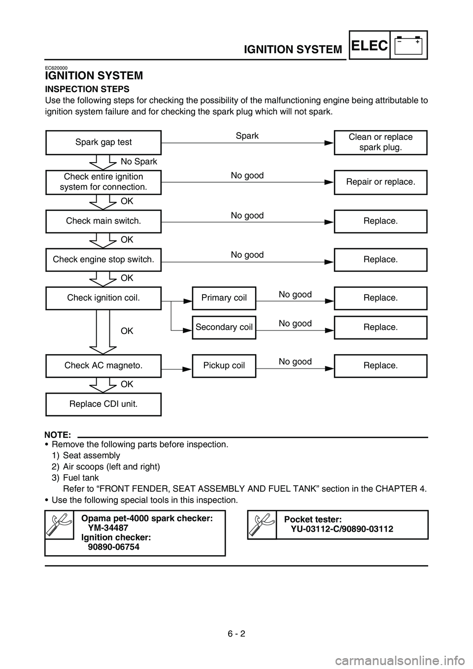
INSPECTION STEPS
Use the following steps for checking the possibility of the malfunctioning engine being attributable to
ignition system failure and for checking the spark plug which will not spark.
NOTE:
Remove the following parts before inspection.
1) Seat assembly
2) Air scoops (left and right)
3) Fuel tank
Refer to “FRONT FENDER, SEAT ASSEMBLY AND FUEL TANK ” section in the CHAPTER 4.
Use the following special tools in this inspection.
Opama pet-4000 spark checker:
YM-34487
Ignition checker: 90890-06754Pocket tester:YU-03112-C/90890-03112
Spark gap test Clean or replace
spark plug.
Check entire ignition
system for connection. Repair or replace.
Check main switch. Replace.
Check engine stop switch. Replace.
Check ignition coil. Primary coil Replace. Secondary coil Replace.
Check AC magneto. Pickup coil Replace. Replace CDI unit.
No Spark
OK
OK
OK
OK
OK
Spark
No good
No good
No good
No good
No good
No good
Page 346 of 390
6 - 3
–+ELECIGNITION SYSTEM
EC622001
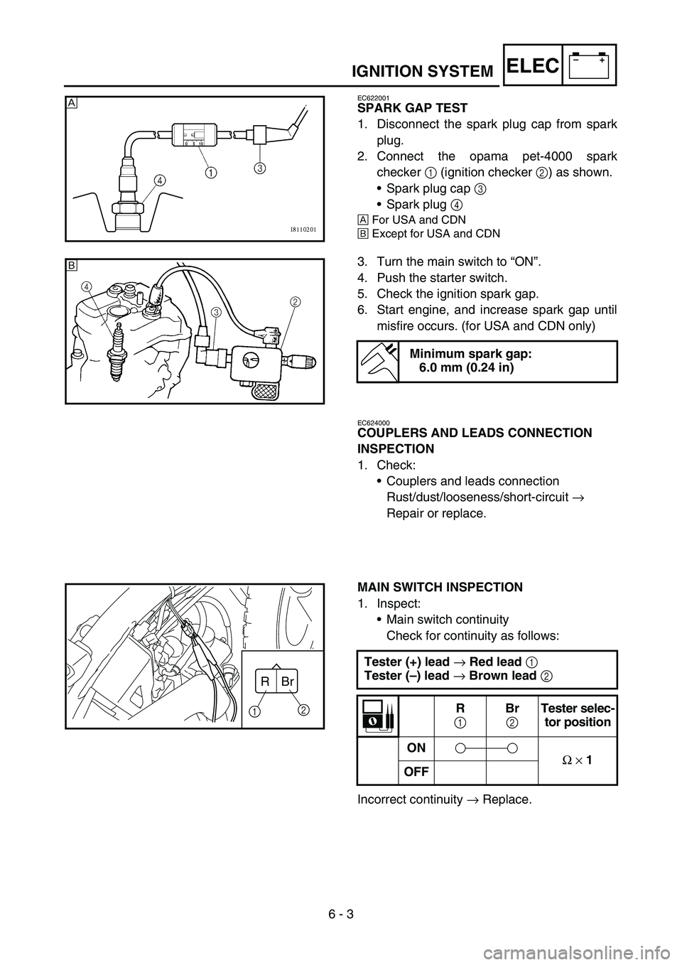
SPARK GAP TEST
1. Disconnect the spark plug cap from spark
plug.
2. Connect the opama pet-4000 spark
checker 1 (ignition checker 2) as shown.
Spark plug cap 3
Spark plug 4
È For USA and CDN
É Except for USA and CDN
3. Turn the main switch to
“ON ”.
4. Push the starter switch.
5. Check the ignition spark gap.
6. Start engine, and increase spark gap until misfire occurs. (for USA and CDN only)
Minimum spark gap:6.0 mm (0.24 in)
È
É
EC624000
COUPLERS AND LEADS CONNECTION
INSPECTION
1. Check:
Couplers and leads connection
Rust/dust/looseness/short-circuit →
Repair or replace.
MAIN SWITCH INSPECTION
1. Inspect: Main switch continuity
Check for continuity as follows:
Incorrect continuity → Replace.
Tester (+) lead
→ Red lead
1
Tester ( –) lead
→ Brown lead
2
R
1 Br
2 Tester selec-
tor position
ON Ω
× 1
OFF
Br
R
1 2
Page 348 of 390
6 - 4
–+ELECIGNITION SYSTEM
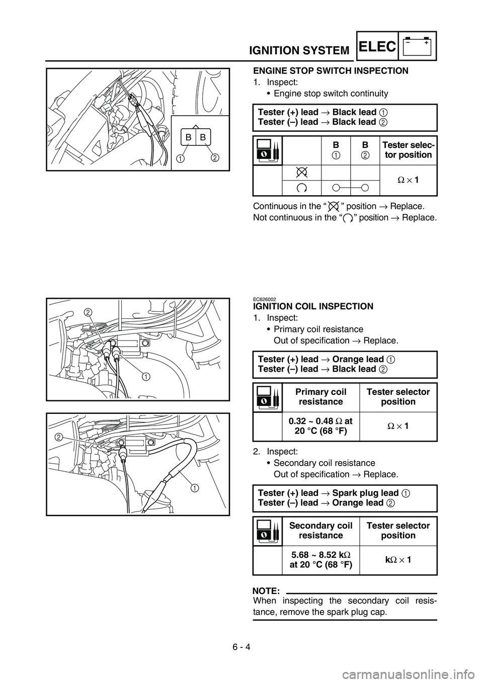
ENGINE STOP SWITCH INSPECTION
1. Inspect:
Engine stop switch continuity
Continuous in the “” position → Replace.
Not continuous in the “” position → Replace.
Tester (+) lead
→ Black lead
1
Tester ( –) lead
→ Black lead
2
B
1 B
2 Tester selec-
tor position
Ω
× 1B
B
1 2
EC626002
IGNITION COIL INSPECTION
1. Inspect:
Primary coil resistance
Out of specification → Replace.
2. Inspect: Secondary coil resistance
Out of specification → Replace.
NOTE:
When inspecting the secondary coil resis-
tance, remove the spark plug cap.Tester (+) lead
→ Orange lead
1
Tester ( –) lead
→ Black lead
2
Primary coil
resistance Tester selector
position
0.32 ~ 0.48 Ω at
20 °C (68 °F) Ω
× 1
Tester (+) lead → Spark plug lead
1
Tester ( –) lead
→ Orange lead
2
Secondary coil
resistance Tester selector
position
5.68 ~ 8.52 k Ω
at 20 °C (68 °F) k
Ω
× 1
1
2
1
2
Page 352 of 390
–+ELEC
6 - 6
ELECTRIC STARTING SYSTEM
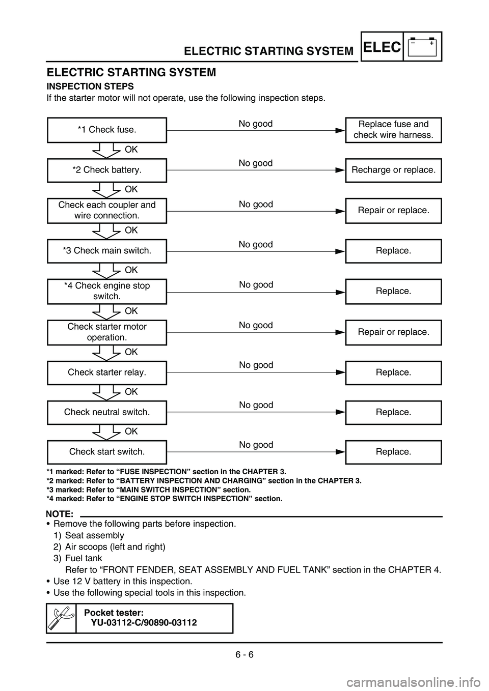
INSPECTION STEPS
If the starter motor will not operate, use the following inspection steps.
*1 marked: Refer to “FUSE INSPECTION ” section in the CHAPTER 3.
*2 marked: Refer to “BATTERY INSPECTION AND CHARGING ” section in the CHAPTER 3.
*3 marked: Refer to “MAIN SWITCH INSPECTION ” section.
*4 marked: Refer to “ENGINE STOP SWITCH INSPECTION ” section.
NOTE:
Remove the following parts before inspection.
1) Seat assembly
2) Air scoops (left and right)
3) Fuel tank
Refer to “FRONT FENDER, SEAT ASSEMBLY AND FUEL TANK ” section in the CHAPTER 4.
Use 12 V battery in this inspection.
Use the following special tools in this inspection.
Pocket tester:
YU-03112-C/90890-03112
*1 Check fuse. Replace fuse and
check wire harness.
*2 Check battery. Recharge or replace.
Check each coupler and wire connection. Repair or replace.
*3 Check main switch. Replace. *4 Check engine stop switch. Replace.
Check starter motor operation. Repair or replace.
Check starter relay. Replace.
Check neutral switch. Replace. Check start switch. Replace.
OK
OK
OK
OK
OK
OK
OK
OK
No good
No good
No good
No good
No good
No good
ELECTRIC STARTING SYSTEM
No good
No good
No good
Page 362 of 390
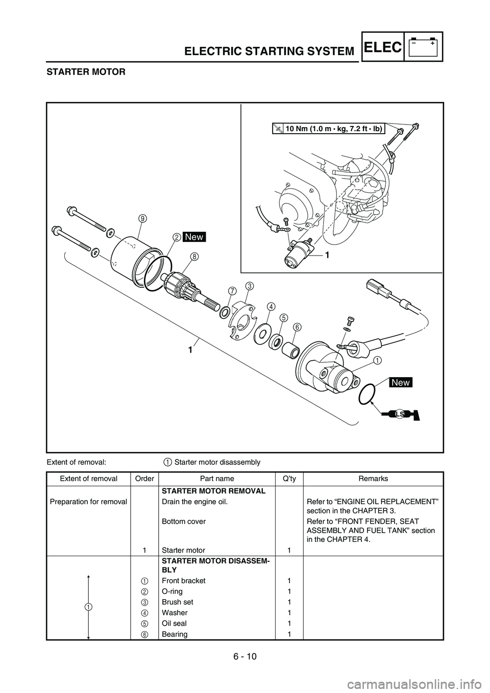
6 - 10
–+ELEC
STARTER MOTOR
1
3
45 6
8
2
\b
1
1
LS
New
New
T R..10 Nm (1.0 m •
kg, 7.2 ft • Ib)
7
Extent of removal:1 Starter motor disassembly
Extent of removal Order Part name Q ’ty Remarks
STARTER MOTOR REMOVAL
Preparation for removal Drain the engine oil. Refer to “ENGINE OIL REPLACEMENT ”
section in the CHAPTER 3.
Bottom cover Refer to “FRONT FENDER, SEAT
ASSEMBLY AND FUEL TANK ” section
in the CHAPTER 4.
1 Starter motor 1 STARTER MOTOR DISASSEM-
BLY
1 Front bracket 1
2 O-ring 1
3 Brush set 1
4 Washer 1
5 Oil seal 1
6 Bearing 1
1
ELECTRIC STARTING SYSTEM