YAMAHA TTR90 2006 User Guide
Manufacturer: YAMAHA, Model Year: 2006, Model line: TTR90, Model: YAMAHA TTR90 2006Pages: 390, PDF Size: 9.12 MB
Page 11 of 390
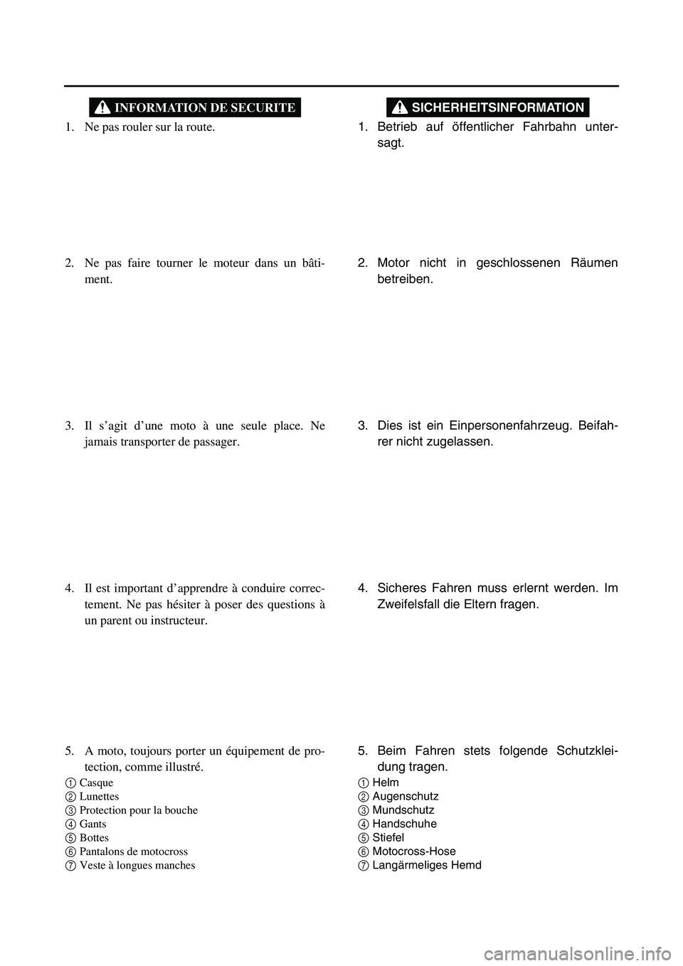
1. Betrieb auf öffentlicher Fahrbahn unter-
sagt.
SICHERHEITSINFORMATION
2. Motor nicht in geschlossenen Räumen
betreiben.
3. Dies ist ein Einpersonenfahrzeug. Beifah-
rer nicht zugelassen.
4. Sicheres Fahren muss erlernt werden. Im
Zweifelsfall die Eltern fragen.
5. Beim Fahren stets folgende Schutzklei-
dung tragen.
1Helm
2Augenschutz
3Mundschutz
4Handschuhe
5Stiefel
6Motocross-Hose
7Langärmeliges Hemd
1. Ne pas rouler sur la route.
INFORMATION DE SECURITE
2. Ne pas faire tourner le moteur dans un bâti-
ment.
3. Il s’agit d’une moto à une seule place. Ne
jamais transporter de passager.
4. Il est important d’apprendre à conduire correc-
tement. Ne pas hésiter à poser des questions à
un parent ou instructeur.
5. A moto, toujours porter un équipement de pro-
tection, comme illustré.
1Casque
2Lunettes
3Protection pour la bouche
4Gants
5Bottes
6Pantalons de motocross
7Veste à longues manches
Page 12 of 390
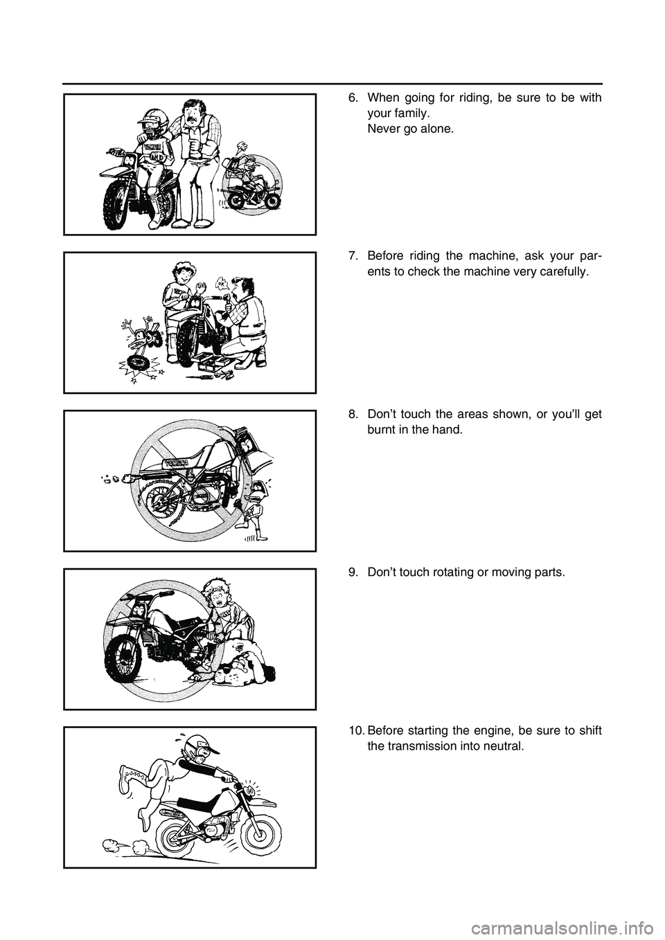
6. When going for riding, be sure to be with
your family.
Never go alone.
7. Before riding the machine, ask your par-
ents to check the machine very carefully.
8. Don’t touch the areas shown, or you’ll get
burnt in the hand.
9. Don’t touch rotating or moving parts.
10. Before starting the engine, be sure to shift
the transmission into neutral.
Page 13 of 390
6. Niemals ohne Aufsicht der Eltern fahren.
Niemals alleine fahren.
7. Vor der Fahrt das Motorrad sorgfältig von
den Eltern prüfen lassen.
8. Die abgebildeten Teile nicht berühren, um
Verbrennungen zu vermeiden.
9. Keine drehenden oder sich bewegenden
Teile berühren.
10. Vor dem Anlassen sicherstellen, dass das
Getriebe in der Leerlaufstellung ist. 6. Toujours partir à moto avec un parent ou ins-
tructeur.
Ne jamais partir seul.
7. Avant de rouler, demander à ce qu’un instruc-
teur ait contrôlé attentivement la moto.
8. Ne jamais toucher les endroits indiqués, car ils
peuvent être chauds. Il y a risque de brûlures.
9. Ne pas toucher les pièces mobiles ou qui tour-
nent.
10. Avant de mettre le moteur en marche, bien
veiller à être au point mort.
Page 14 of 390
EC080000
HOW TO USE
THIS MANUAL
EC081000
PARTICULARLY IMPORTANT
INFORMATION
The Safety Alert Symbol means ATTENTION!
BECOME ALERT! YOUR SAFETY IS
INVOLVED!
Failure to follow WARNING instructions could
result in severe injury or death to the machine
operator, a bystander, or a person inspecting
or repairing the machine.
A CAUTION indicates special precautions that
must be taken to avoid damage to the
machine.
NOTE:
A NOTE provides key information to make pro-
cedures easier or clearer.
WARNING
CAUTION:
EC082000
FINDING THE REQUIRED PAGE
1. This manual consists of six chapters; “Gen-
eral Information”, “Specifications”, “Regular
inspection and adjustments”, “Engine”,
“Chassis” and “Electrical”.
2. The table of contents is at the beginning of
the manual. Look over the general layout of
the book before finding then required chap-
ter and item.
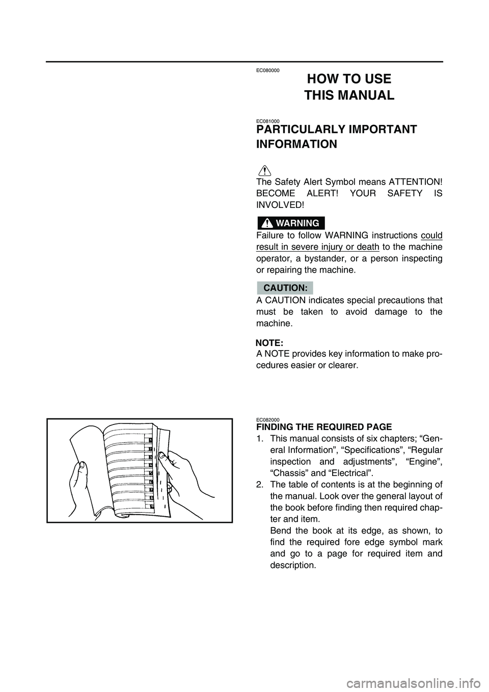
Bend the book at its edge, as shown, to
find the required fore edge symbol mark
and go to a page for required item and
description.
Page 15 of 390
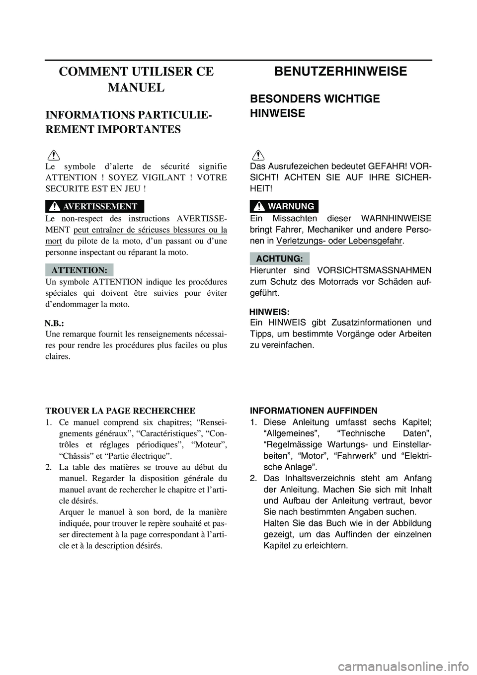
BENUTZERHINWEISE
BESONDERS WICHTIGE
HINWEISE
Das Ausrufezeichen bedeutet GEFAHR! VOR-
SICHT! ACHTEN SIE AUF IHRE SICHER-
HEIT!
Ein Missachten dieser WARNHINWEISE
bringt Fahrer, Mechaniker und andere Perso-
nen in Verletzungs- oder Lebensgefahr
.
Hierunter sind VORSICHTSMASSNAHMEN
zum Schutz des Motorrads vor Schäden auf-
geführt.
HINWEIS:
Ein HINWEIS gibt Zusatzinformationen und
Tipps, um bestimmte Vorgänge oder Arbeiten
zu vereinfachen.
WARNUNG
ACHTUNG:
INFORMATIONEN AUFFINDEN
1. Diese Anleitung umfasst sechs Kapitel;
“Allgemeines”, “Technische Daten”,
“Regelmässige Wartungs- und Einstellar-
beiten”, “Motor”, “Fahrwerk” und “Elektri-
sche Anlage”.
2. Das Inhaltsverzeichnis steht am Anfang
der Anleitung. Machen Sie sich mit Inhalt
und Aufbau der Anleitung vertraut, bevor
Sie nach bestimmten Angaben suchen.
Halten Sie das Buch wie in der Abbildung
gezeigt, um das Auffinden der einzelnen
Kapitel zu erleichtern.
COMMENT UTILISER CE
MANUEL
INFORMATIONS PARTICULIE-
REMENT IMPORTANTES
Le symbole d’alerte de sécurité signifie
ATTENTION ! SOYEZ VIGILANT ! VOTRE
SECURITE EST EN JEU !
Le non-respect des instructions AVERTISSE-
MENT peut entraîner de sérieuses blessures ou la
mort du pilote de la moto, d’un passant ou d’une
personne inspectant ou réparant la moto.
Un symbole ATTENTION indique les procédures
spéciales qui doivent être suivies pour éviter
d’endommager la moto.
N.B.:
Une remarque fournit les renseignements nécessai-
res pour rendre les procédures plus faciles ou plus
claires.
AVERTISSEMENT
ATTENTION:
TROUVER LA PAGE RECHERCHEE
1. Ce manuel comprend six chapitres; “Rensei-
gnements généraux”, “Caractéristiques”, “Con-
trôles et réglages périodiques”, “Moteur”,
“Châssis” et “Partie électrique”.
2. La table des matières se trouve au début du
manuel. Regarder la disposition générale du
manuel avant de rechercher le chapitre et l’arti-
cle désirés.
Arquer le manuel à son bord, de la manière
indiquée, pour trouver le repère souhaité et pas-
ser directement à la page correspondant à l’arti-
cle et à la description désirés.
Page 16 of 390
EC083000
MANUAL FORMAT
All of the procedures in this manual are organized in a sequential, step-by-step format. The informa-
tion has been complied to provide the mechanic with an easy to read, handy reference that contains
comprehensive explanations of all disassembly, repair, assembly, and inspection operations.
In this revised format, the condition of a faulty component will precede an arrow symbol and the
course of action required will follow the symbol, e.g.
Bearings
Pitting/damage →
Replace.
EC084002
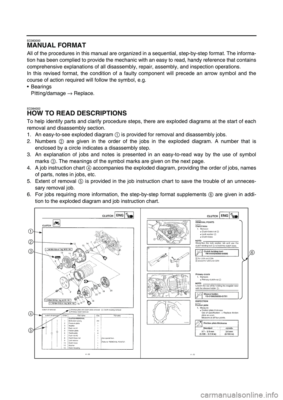
HOW TO READ DESCRIPTIONS
To help identify parts and clarify procedure steps, there are exploded diagrams at the start of each
removal and disassembly section.
1. An easy-to-see exploded diagram 1
is provided for removal and disassembly jobs.
2. Numbers 2
are given in the order of the jobs in the exploded diagram. A number that is
enclosed by a circle indicates a disassembly step.
3. An explanation of jobs and notes is presented in an easy-to-read way by the use of symbol
marks 3
. The meanings of the symbol marks are given on the next page.
4. A job instruction chart 4
accompanies the exploded diagram, providing the order of jobs, names
of parts, notes in jobs, etc.
5. Extent of removal 5
is provided in the job instruction chart to save the trouble of an unneces-
sary removal job.
6. For jobs requiring more information, the step-by-step format supplements 6
are given in addi-
tion to the exploded diagram and job instruction chart.
Page 17 of 390
AUFBAU DER ANLEITUNG
Sämtliche Arbeitsvorgänge in dieser Anleitung
sind in der entsprechenden Reihenfolge dar-
gestellt. Diese Anleitung wurde zusammenge-
stellt, um dem Benutzer ein leicht
verständliches Nachschlagewerk in die Hand
zu geben, in dem Ein- und Ausbau, Zerlegung
und Zusammenbau, Prüfung und Reparatur
detailliert beschrieben sind.
Je nach Zustand eines fehlerhaften Bauteils
weist ein Pfeilsymbol auf die erforderliche
Maßnahme hin. Beispiel:
Lager
Angefressen/beschädigt → Erneuern.
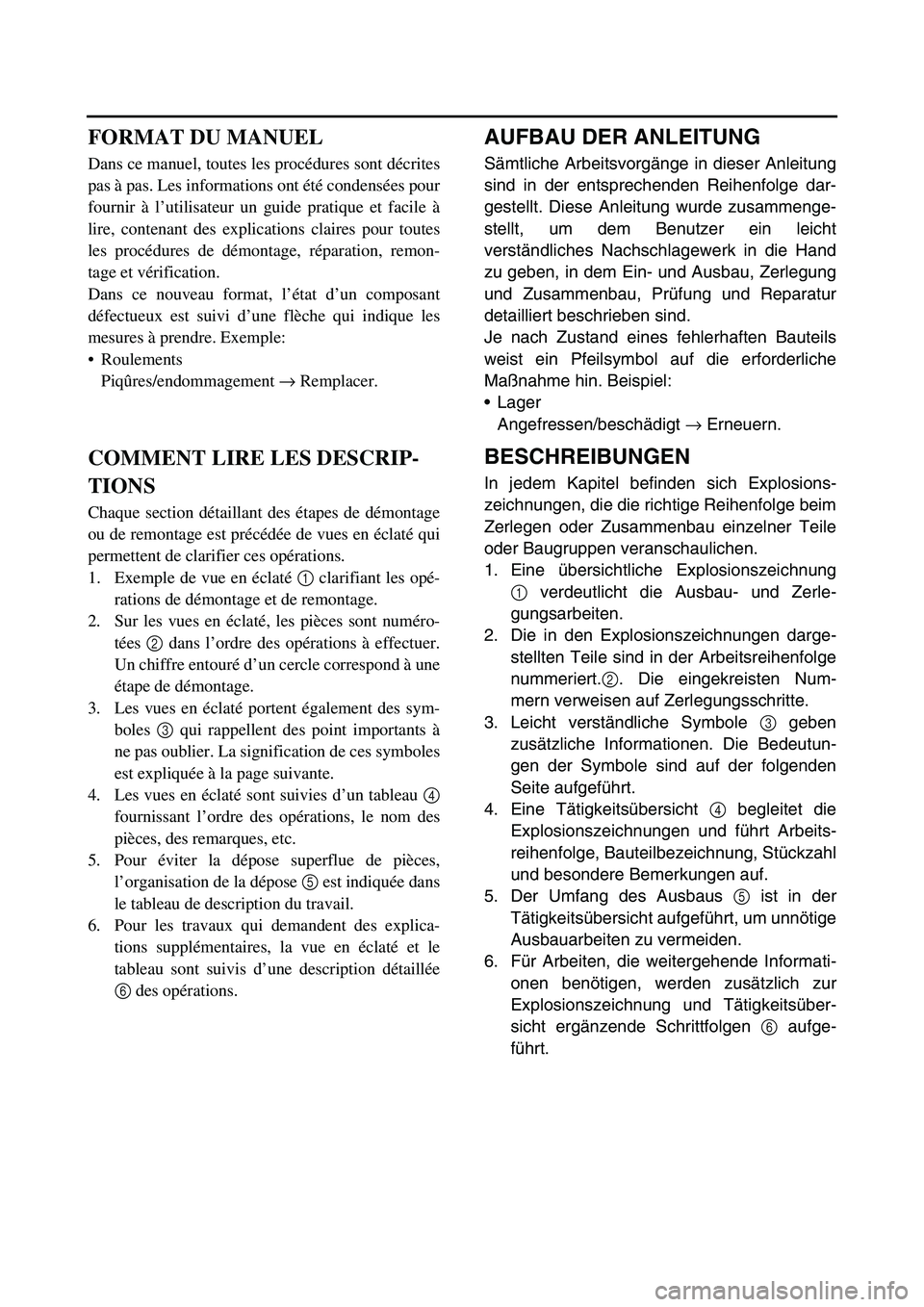
BESCHREIBUNGEN
In jedem Kapitel befinden sich Explosions-
zeichnungen, die die richtige Reihenfolge beim
Zerlegen oder Zusammenbau einzelner Teile
oder Baugruppen veranschaulichen.
1. Eine übersichtliche Explosionszeichnung
1 verdeutlicht die Ausbau- und Zerle-
gungsarbeiten.
2. Die in den Explosionszeichnungen darge-
stellten Teile sind in der Arbeitsreihenfolge
nummeriert.2. Die eingekreisten Num-
mern verweisen auf Zerlegungsschritte.
3. Leicht verständliche Symbole 3 geben
zusätzliche Informationen. Die Bedeutun-
gen der Symbole sind auf der folgenden
Seite aufgeführt.
4. Eine Tätigkeitsübersicht 4 begleitet die
Explosionszeichnungen und führt Arbeits-
reihenfolge, Bauteilbezeichnung, Stückzahl
und besondere Bemerkungen auf.
5. Der Umfang des Ausbaus 5 ist in der
Tätigkeitsübersicht aufgeführt, um unnötige
Ausbauarbeiten zu vermeiden.
6. Für Arbeiten, die weitergehende Informati-
onen benötigen, werden zusätzlich zur
Explosionszeichnung und Tätigkeitsüber-
sicht ergänzende Schrittfolgen 6 aufge-
führt.
FORMAT DU MANUEL
Dans ce manuel, toutes les procédures sont décrites
pas à pas. Les informations ont été condensées pour
fournir à l’utilisateur un guide pratique et facile à
lire, contenant des explications claires pour toutes
les procédures de démontage, réparation, remon-
tage et vérification.
Dans ce nouveau format, l’état d’un composant
défectueux est suivi d’une flèche qui indique les
mesures à prendre. Exemple:
Roulements
Piqûres/endommagement → Remplacer.
COMMENT LIRE LES DESCRIP-
TIONS
Chaque section détaillant des étapes de démontage
ou de remontage est précédée de vues en éclaté qui
permettent de clarifier ces opérations.
1. Exemple de vue en éclaté 1 clarifiant les opé-
rations de démontage et de remontage.
2. Sur les vues en éclaté, les pièces sont numéro-
tées 2 dans l’ordre des opérations à effectuer.
Un chiffre entouré d’un cercle correspond à une
étape de démontage.
3. Les vues en éclaté portent également des sym-
boles 3 qui rappellent des point importants à
ne pas oublier. La signification de ces symboles
est expliquée à la page suivante.
4. Les vues en éclaté sont suivies d’un tableau 4
fournissant l’ordre des opérations, le nom des
pièces, des remarques, etc.
5. Pour éviter la dépose superflue de pièces,
l’organisation de la dépose 5 est indiquée dans
le tableau de description du travail.
6. Pour les travaux qui demandent des explica-
tions supplémentaires, la vue en éclaté et le
tableau sont suivis d’une description détaillée
6 des opérations.
Page 18 of 390
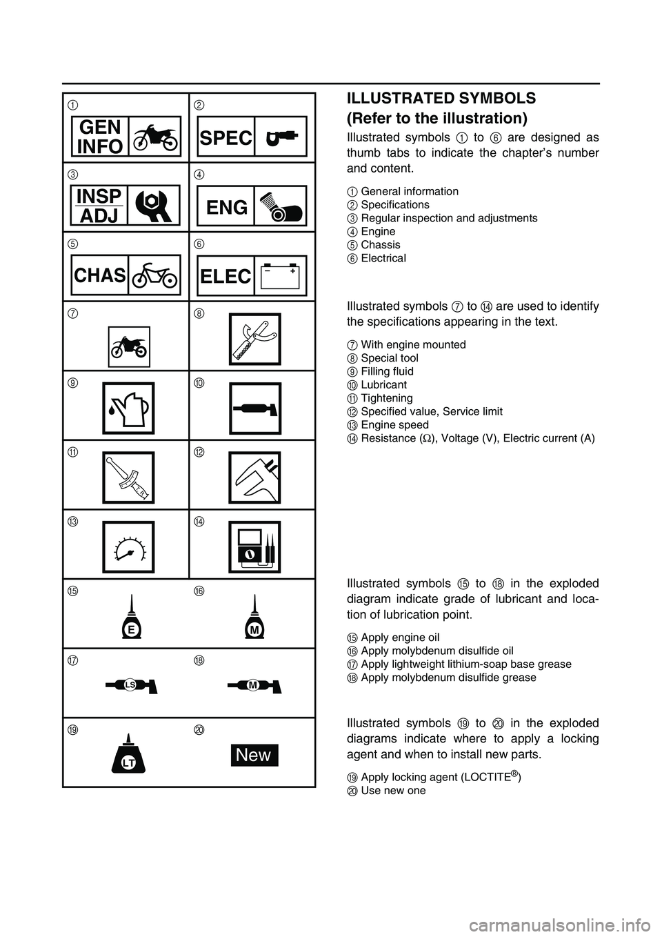
ILLUSTRATED SYMBOLS
(Refer to the illustration)
Illustrated symbols 1 to 6 are designed as
thumb tabs to indicate the chapter’s number
and content.
1General information
2Specifications
3Regular inspection and adjustments
4Engine
5Chassis
6Electrical
Illustrated symbols 7 to D are used to identify
the specifications appearing in the text.
7With engine mounted
8Special tool
9Filling fluid
0Lubricant
ATightening
BSpecified value, Service limit
CEngine speed
DResistance (
Ω), Voltage (V), Electric current (A)
Illustrated symbols E to H in the exploded
diagram indicate grade of lubricant and loca-
tion of lubrication point.
EApply engine oil
FApply molybdenum disulfide oil
GApply lightweight lithium-soap base grease
HApply molybdenum disulfide grease
Illustrated symbols I to J in the exploded
diagrams indicate where to apply a locking
agent and when to install new parts.
IApply locking agent (LOCTITE®)
JUse new one 12
34
56
78
90
AB
CD
E
F
G
H
IJ
GEN
INFOSPEC
INSP
ADJ
ENG
CHAS–+ELEC
T R..
EM
LSM
LTNew
Page 19 of 390
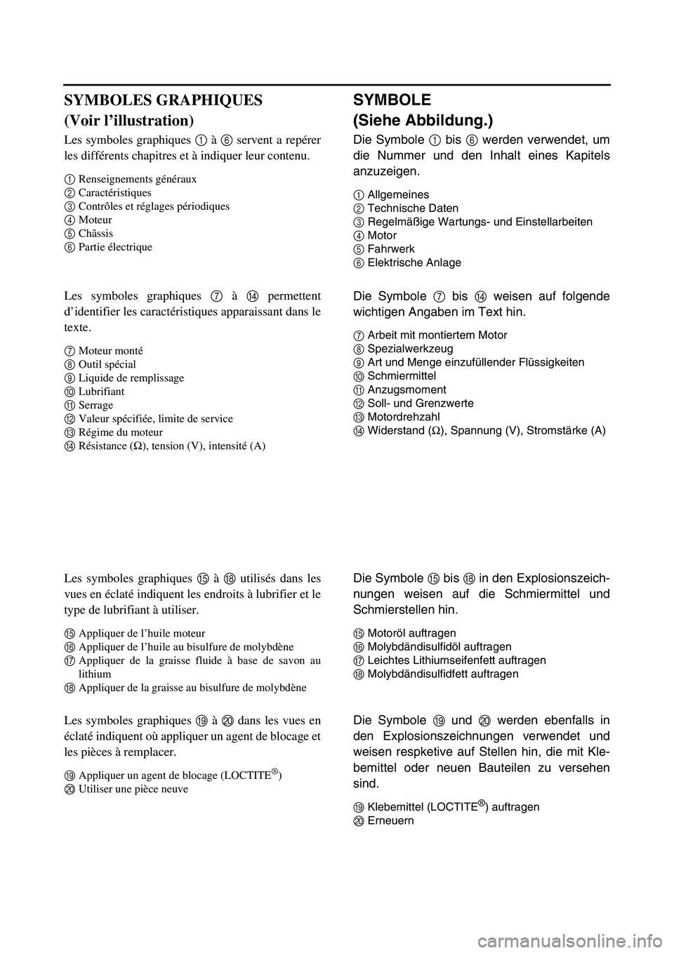
SYMBOLE
(Siehe Abbildung.)
Die Symbole 1 bis 6 werden verwendet, um
die Nummer und den Inhalt eines Kapitels
anzuzeigen.
1Allgemeines
2Technische Daten
3Regelmäßige Wartungs- und Einstellarbeiten
4Motor
5Fahrwerk
6Elektrische Anlage
Die Symbole 7 bis D weisen auf folgende
wichtigen Angaben im Text hin.
7Arbeit mit montiertem Motor
8Spezialwerkzeug
9Art und Menge einzufüllender Flüssigkeiten
0Schmiermittel
AAnzugsmoment
BSoll- und Grenzwerte
CMotordrehzahl
DWiderstand (
Ω), Spannung (V), Stromstärke (A)
Die Symbole E bis H in den Explosionszeich-
nungen weisen auf die Schmiermittel und
Schmierstellen hin.
EMotoröl auftragen
FMolybdändisulfidöl auftragen
GLeichtes Lithiumseifenfett auftragen
HMolybdändisulfidfett auftragen
Die Symbole I und J werden ebenfalls in
den Explosionszeichnungen verwendet und
weisen respketive auf Stellen hin, die mit Kle-
bemittel oder neuen Bauteilen zu versehen
sind.
IKlebemittel (LOCTITE®) auftragen
JErneuern
SYMBOLES GRAPHIQUES
(Voir l’illustration)
Les symboles graphiques 1 à 6 servent a repérer
les différents chapitres et à indiquer leur contenu.
1Renseignements généraux
2Caractéristiques
3Contrôles et réglages périodiques
4Moteur
5Châssis
6Partie électrique
Les symboles graphiques 7 à D permettent
d’identifier les caractéristiques apparaissant dans le
texte.
7Moteur monté
8Outil spécial
9Liquide de remplissage
0Lubrifiant
ASerrage
BValeur spécifiée, limite de service
CRégime du moteur
DRésistance (
Ω), tension (V), intensité (A)
Les symboles graphiques E à H utilisés dans les
vues en éclaté indiquent les endroits à lubrifier et le
type de lubrifiant à utiliser.
EAppliquer de l’huile moteur
FAppliquer de l’huile au bisulfure de molybdène
GAppliquer de la graisse fluide à base de savon au
lithium
HAppliquer de la graisse au bisulfure de molybdène
Les symboles graphiques I à J dans les vues en
éclaté indiquent où appliquer un agent de blocage et
les pièces à remplacer.
IAppliquer un agent de blocage (LOCTITE®)
JUtiliser une pièce neuve
Page 20 of 390
INDEX
GENERAL INFORMATION
SPECIFICATIONS
REGULAR INSPECTION AND ADJUSTMENTS
ENGINE
CHASSIS
ELECTRICAL