engine YAMAHA TTR90 2006 Owner's Manual
[x] Cancel search | Manufacturer: YAMAHA, Model Year: 2006, Model line: TTR90, Model: YAMAHA TTR90 2006Pages: 390, PDF Size: 9.12 MB
Page 56 of 390
GEN
INFO
ANLASSEN UND
INBETRIEBNAHME
ACHTUNG:
Vor dem Start muss die “Routinekontrolle
vor Fahrtbeginn” ausgeführt werden.
WARNUNG
Den Motor niemals in einem geschlosse-
nen Raum anlassen oder betreiben. Motor-
abgase sind äußerst giftig und führen in
kurzer Zeit zu Bewusstlosigkeit und Tod.
Daher den Motor nur an einem gut belüfte-
ten Ort betreiben.
KALTEN MOTOR ANLASSEN
TT-R90
WARNUNG
Vor dem Anlassen sicherstellen, dass das
Getriebe in der Leerlaufstellung ist.
1. Den Kraftstoffhahn auf “ON” stellen.
2. Den Choke betätigen und den Gasdrehgriff
ganz schließen.
3. Den Motorstoppschalter “ENGINE STOP”
auf “” stellen.
4. Den Kickstarterhebel kräftig durchtreten,
um den Motor anzulassen.
5. Nach dem Anlassen den Motor einige Minu-
ten lang warm laufen lassen. Vor dem Anfah-
ren sicherstellen, dass der Chokehebel in die
Ausgangsstellung zurückgebracht wird.
TT-R90E
WARNUNG
Vor dem Anlassen sicherstellen, dass das
Getriebe in der Leerlaufstellung ist.
HINWEIS:
Das Motorrad ist mit einem Zündunterbre-
chungs- und Anlasssperrschalter-System
ausgerüstet. Der Motor kann nur dann mit
dem E-Starter angelassen werden, wenn
das Getriebe in der Leerlaufstellung ist.
Falls der Motor bei Verwendung des Elektro-
starters nicht sofort anspringt, den Starterschal-
ter freigeben und einige Sekunden bis zum
nächsten Startversuch warten. Um die Batterie
zu schonen, darf der Starterschalter jeweils nur
kurzzeitig betätigt werden. Den Motor niemals
länger als 10 Sekunden drehen. Falls der Motor
nicht mit dem Elektrostarter angelassen werden
kann, den Kickstarter benutzen.1. Den Kraftstoffhahn auf “ON” stellen.
2. Den Zündschlüssel auf “ON” stellen.
3. Das Getriebe in die Leerlaufstellung schalten.
4. Den Choke betätigen und den Gasdrehgriff
ganz schließen.
5. Den Motorstoppschalter “ENGINE STOP”
auf “” stellen.
6. Den Starterschalter drücken oder den Kick-
starterhebel durchtreten, um den Motor
anzulassen.
7. Nach dem Anlassen den Motor einige Minu-
ten lang warm laufen lassen. Vor dem Anfah-
ren sicherstellen, dass der Chokehebel in die
Ausgangsstellung zurückgebracht wird.
WARMEN MOTOR ANLASSEN
Den warmen Motor wie im Abschnitt “Kalten
Motor anlassen” beschrieben anlassen. Aller-
dings sollte der Choke nicht betätigt werden.
Den Gasdrehgriff leicht öffnen.
ACHTUNG:
Vor der ersten Inbetriebnahme unbedingt den
Abschnitt “Einfahrvorschriften” beachten.
MOTOR WARM FAHREN
Den Motor stets warm fahren, um ihm eine lange
Lebensdauer zu gewähren. Bei kaltem Motor
niemals stark beschleunigen! Der Motor ist aus-
reichend warmgefahren, wenn er bei abgeschal-
tetem Choke willig auf Gasgeben anspricht.
WARNUNG
Vor dem Losfahren sicherstellen, dass der
Seitenständer hochgeklappt bzw. abge-
nommen ist.
Ein ausgeklappter Seitenständer kann in
Kurven schwere Stürze verursachen.
EINFAHRVORSCHRIFTEN
Die Einfahrzeit ist wichtig, weil sie den vielen
Bauteilen des Motors erlaubt, sich einzupas-
sen. Außerdem kann der Fahrer sich während
dessen mit seiner Maschine vertraut machen.
Während der ersten fünf Betriebsstunden
unbedingt Vollgas vermeiden.
Nach der Probefahrt die Maschine auf lockere
Schraubverbindungen, Öllecks und andere
Probleme untersuchen.
Die Maschine gründlich kontrollieren und einstel-
len, insbesondere Seilzüge, Antriebskette und
Radspeichen.
ACHTUNG:
Am Ende der Einfahrzeit sicherstellen, dass
sämtliche Schraubverbindungen fest sind.
Bei Lockerheit nachziehen.
ANLASSEN UND INBETRIEBNAHME
1 - 13
Page 57 of 390
GEN
INFO
1 - 14
CLEANING AND STORAGE
EC1B0000
CLEANING AND STORAGE
EC1B1000
CLEANING
Frequent cleaning of your machine will
enhance its appearance, maintain good overall
performance, and extend the life of many com-
ponents.
1. Before washing the machine, block off the
end of the exhaust pipe to prevent water
from entering.
2. If the engine is excessively greasy, apply
some degreaser to it with a paint brush. Do
not apply degreaser to the chain, sprock-
ets, or wheel axles.
3. Rinse the dirt and degreaser off with a gar-
den hose; use only enough pressure to do
the job.
CAUTION:
Excessive hose pressure may cause water
seepage and contamination of wheel bear-
ings, front forks, brakes and transmission
seals. Many expensive repair bills have
resulted from improper high pressure
detergent applications such as those avail-
able in coin-operated car washers.
4. After the majority of the dirt has been
hosed off, wash all surfaces with warm
water and a mild detergent. Use an old
toothbrush to clean hard-to-reach places.
5. Rinse the machine off immediately with
clean water, and dry all surfaces with a soft
towel or cloth.
6. Immediately after washing, remove excess
water from the chain with a paper towel
and lubricate the chain to prevent rust.
7. Clean the seat with a vinyl upholstery
cleaner to keep the cover pliable and
glossy.
8. Automotive wax may be applied to all
painted or chromed surfaces. Avoid combi-
nation cleaner-waxes, as they may contain
abrasives.
9. After completing the above, start the
engine and allow it to idle for several min-
utes.
EC182001
STORAGE
If your machine is to be stored for 60 days or
more, some preventive measures must be
taken to avoid deterioration. After cleaning the
machine thoroughly, prepare it for storage as
follows:
1. Drain the fuel tank, fuel lines, and the car-
buretor float bowl.
2. Remove the spark plug, pour a tablespoon
of SAE 10W-30 motor oil in the spark plug
hole, and reinstall the plug. With the engine
stop switch pushed in, kick the engine over
several times to coat the cylinder walls with
oil.
3. Remove the drive chain, clean it thoroughly
with solvent, and lubricate it. Reinstall the
chain or store it in a plastic bag tied to the
frame.
4. Lubricate all control cables.
5. Block the frame up to raise the wheels off
the ground.
6. Tie a plastic bag over the exhaust pipe out-
let to prevent moisture from entering.
7. If the machine is to be stored in a humid or
salt-air environment, coat all exposed
metal surfaces with a film of light oil. Do not
apply oil to rubber parts or the seat cover.
NOTE:
Make any necessary repairs before the
machine is stored.
Page 60 of 390
SPEC
2 - 1
EC200000
SPECIFICATIONS
EC211000
GENERAL SPECIFICATIONS
Model name: TT-R90V (CDN, AUS, NZ)
TT-R90 (Europe, ZA)
TT-R90EV (USA, CDN, AUS, NZ)
TT-R90E (Europe, ZA)
Model code number: TT-R90:
5HNW (Europe, AUS, NZ, ZA)
5HNX (CDN)
TT-R90E:
3P21 (USA)
3P22 (Europe, AUS, NZ, ZA)
3P23 (CDN)
Dimensions:
Overall length 1,525 mm (57.0 in)
Overall width 605 mm (23.8 in)
Overall height 865 mm (34.1 in)
Seat height 625 mm (24.6 in)
Wheelbase 1,040 mm (40.9 in)
Minimum ground clearance 160 mm (6.3 in)
Dry weight:
Without oil and fuel (TT-R90) 60.0 kg (132.3 lb)
(TT-R90E) 63.0 kg (138.9 lb)
Engine:
Engine type Air cooled 4-stroke, SOHC
Cylinder arrangement Single cylinder, forward inclined
Displacement 89 cm
3 (5.43 cu.in)
Bore × stroke 47.0 × 51.8 mm (1.85 × 2.04 in)
Compression ratio 8.5 : 1
Compression pressure (STD) 1,000 kPa (10 kg/cm
2, 145 psi) at 1,000 r/min
Starting system (TT-R90) Kick starter
(TT-R90E) Kick and electric starter
Lubrication system: Wet sump
GENERAL SPECIFICATIONS
Page 61 of 390
SPEC
2 - 2 Oil type or grade:
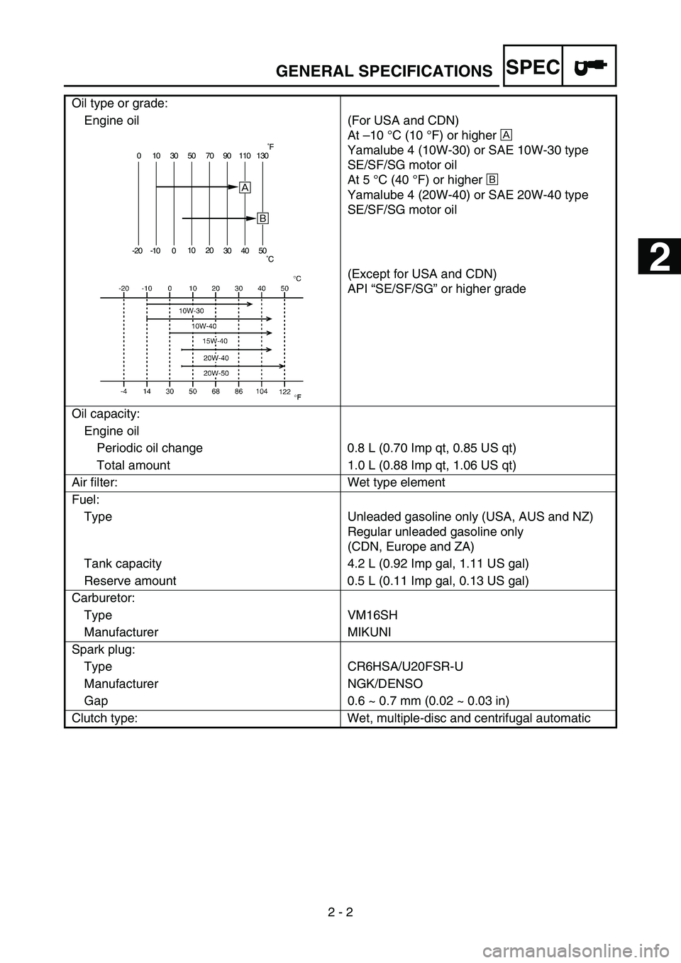
Engine oil
(For USA and CDN)
At –10 °C (10 °F) or higher È
Yamalube 4 (10W-30) or SAE 10W-30 type
SE/SF/SG motor oil
At 5 °C (40 °F) or higher É
Yamalube 4 (20W-40) or SAE 20W-40 type
SE/SF/SG motor oil
(Except for USA and CDN)
API “SE/SF/SG” or higher grade
Oil capacity:
Engine oil
Periodic oil change 0.8 L (0.70 Imp qt, 0.85 US qt)
Total amount 1.0 L (0.88 Imp qt, 1.06 US qt)
Air filter: Wet type element
Fuel:
Type Unleaded gasoline only (USA, AUS and NZ)
Regular unleaded gasoline only
(CDN, Europe and ZA)
Tank capacity 4.2 L (0.92 Imp gal, 1.11 US gal)
Reserve amount 0.5 L (0.11 Imp gal, 0.13 US gal)
Carburetor:
Type VM16SH
Manufacturer MIKUNI
Spark plug:
Type CR6HSA/U20FSR-U
Manufacturer NGK/DENSO
Gap 0.6 ~ 0.7 mm (0.02 ~ 0.03 in)
Clutch type: Wet, multiple-disc and centrifugal automatic
0 10 30 50 70 90 110 130
-20 -10 01020
30 40 50
È
É
˚F
˚C
GENERAL SPECIFICATIONS
1
2
Page 63 of 390
SPEC
2 - 4
MAINTENANCE SPECIFICATIONS
ENGINE
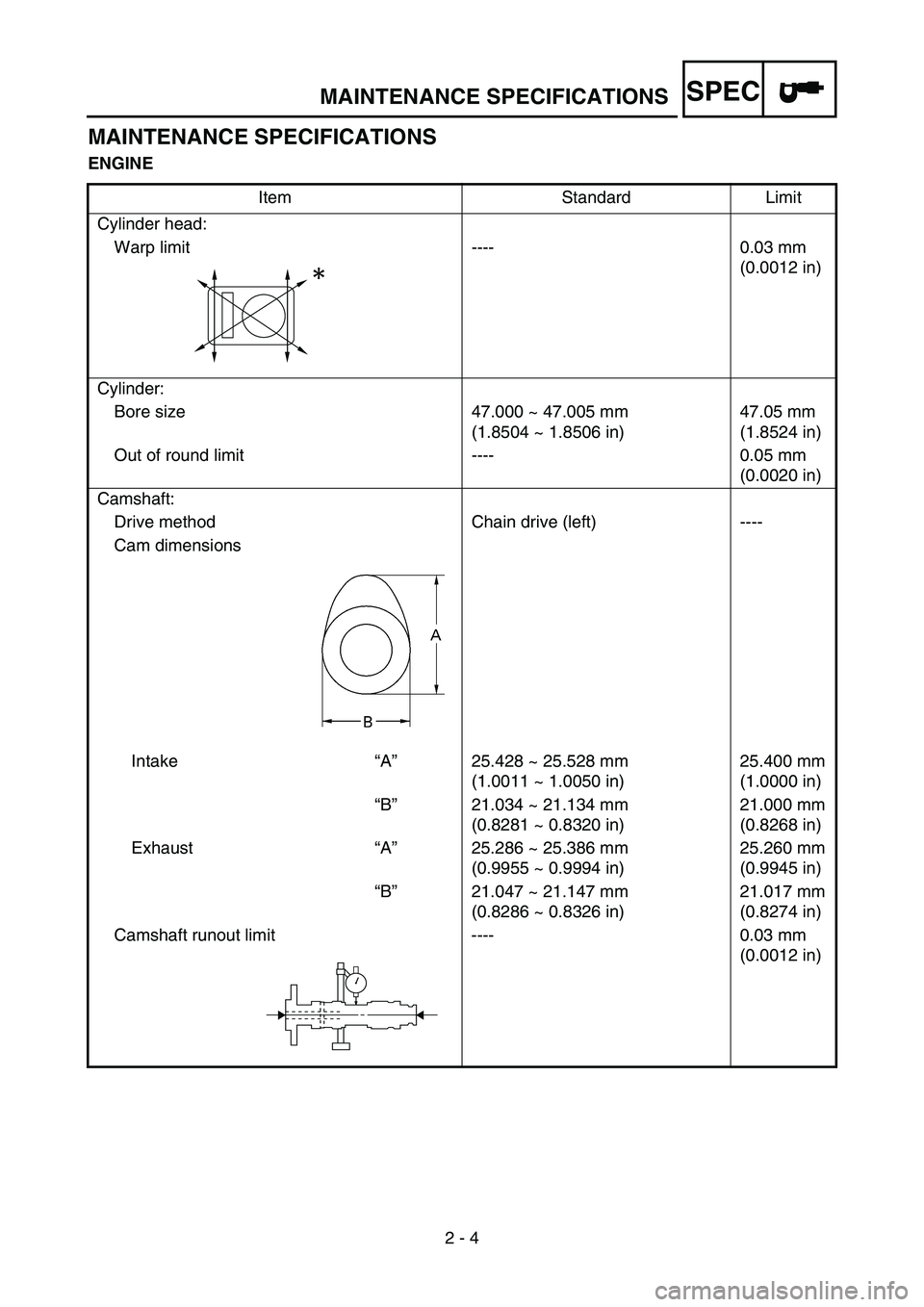
Item Standard Limit
Cylinder head:
Warp limit ---- 0.03 mm
(0.0012 in)
Cylinder:
Bore size 47.000 ~ 47.005 mm
(1.8504 ~ 1.8506 in)47.05 mm
(1.8524 in)
Out of round limit ---- 0.05 mm
(0.0020 in)
Camshaft:
Drive method Chain drive (left) ----
Cam dimensions
Intake“A”25.428 ~ 25.528 mm
(1.0011 ~ 1.0050 in)25.400 mm
(1.0000 in)
“B”21.034 ~ 21.134 mm
(0.8281 ~ 0.8320 in)21.000 mm
(0.8268 in)
Exhaust“A”25.286 ~ 25.386 mm
(0.9955 ~ 0.9994 in)25.260 mm
(0.9945 in)
“B”21.047 ~ 21.147 mm
(0.8286 ~ 0.8326 in)21.017 mm
(0.8274 in)
Camshaft runout limit ---- 0.03 mm
(0.0012 in)
MAINTENANCE SPECIFICATIONS
Page 67 of 390
SPEC
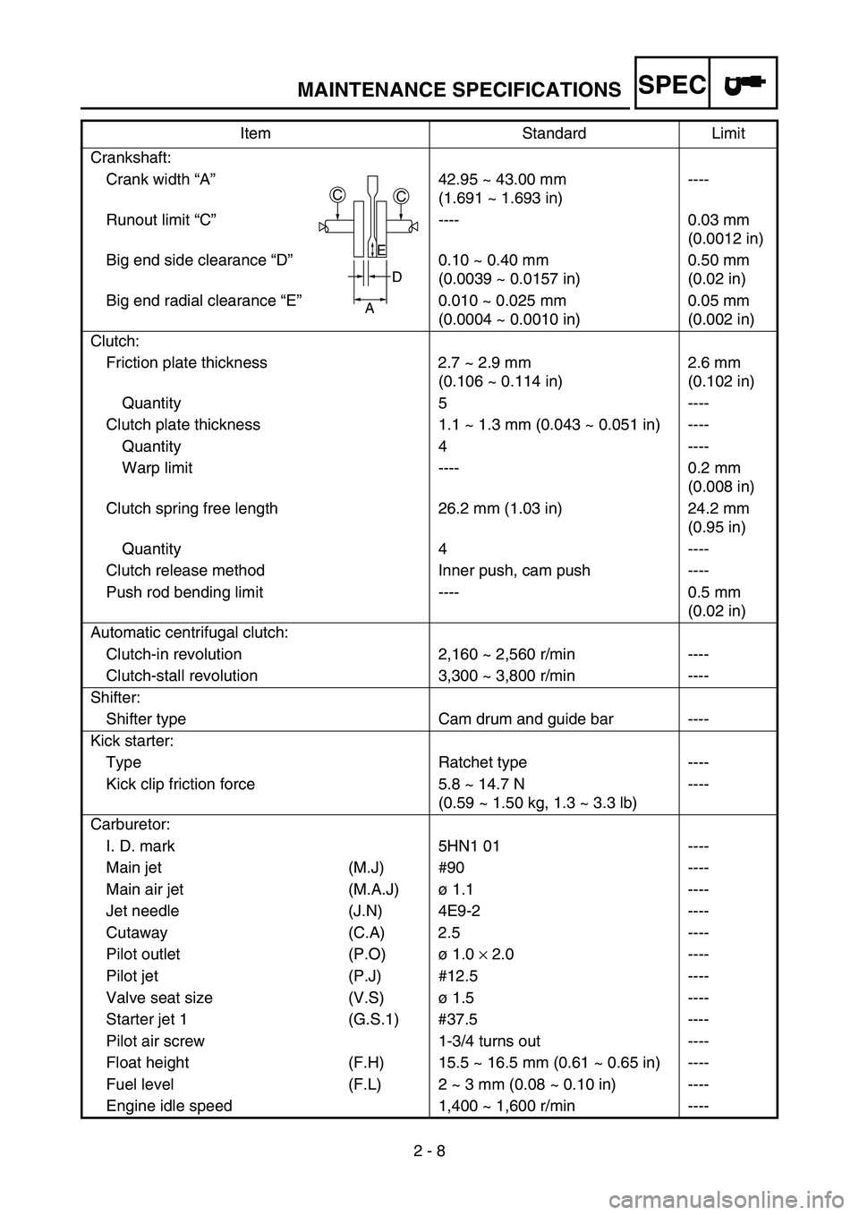
2 - 8 Crankshaft:
Crank width “A”42.95 ~ 43.00 mm
(1.691 ~ 1.693 in)----
Runout limit “C”---- 0.03 mm
(0.0012 in)
Big end side clearance “D”0.10 ~ 0.40 mm
(0.0039 ~ 0.0157 in)0.50 mm
(0.02 in)
Big end radial clearance “E”0.010 ~ 0.025 mm
(0.0004 ~ 0.0010 in)0.05 mm
(0.002 in)
Clutch:
Friction plate thickness 2.7 ~ 2.9 mm
(0.106 ~ 0.114 in)2.6 mm
(0.102 in)
Quantity 5 ----
Clutch plate thickness 1.1 ~ 1.3 mm (0.043 ~ 0.051 in) ----
Quantity 4 ----
Warp limit ---- 0.2 mm
(0.008 in)
Clutch spring free length 26.2 mm (1.03 in) 24.2 mm
(0.95 in)
Quantity 4 ----
Clutch release method Inner push, cam push ----
Push rod bending limit ---- 0.5 mm
(0.02 in)
Automatic centrifugal clutch:
Clutch-in revolution 2,160 ~ 2,560 r/min ----
Clutch-stall revolution 3,300 ~ 3,800 r/min ----
Shifter:
Shifter type Cam drum and guide bar ----
Kick starter:
Type Ratchet type ----
Kick clip friction force 5.8 ~ 14.7 N
(0.59 ~ 1.50 kg, 1.3 ~ 3.3 lb)----
Carburetor:
I. D. mark 5HN1 01 ----
Main jet (M.J) #90 ----
Main air jet (M.A.J)ø 1.1 ----
Jet needle (J.N) 4E9-2 ----
Cutaway (C.A) 2.5 ----
Pilot outlet (P.O)ø 1.0 × 2.0 ----
Pilot jet (P.J) #12.5 ----
Valve seat size (V.S)ø 1.5 ----
Starter jet 1 (G.S.1) #37.5 ----
Pilot air screw 1-3/4 turns out ----
Float height (F.H) 15.5 ~ 16.5 mm (0.61 ~ 0.65 in) ----
Fuel level (F.L) 2 ~ 3 mm (0.08 ~ 0.10 in) ----
Engine idle speed 1,400 ~ 1,600 r/min ----Item Standard Limit
CC
D
A
E
MAINTENANCE SPECIFICATIONS
Page 72 of 390
SPEC
2 - 13
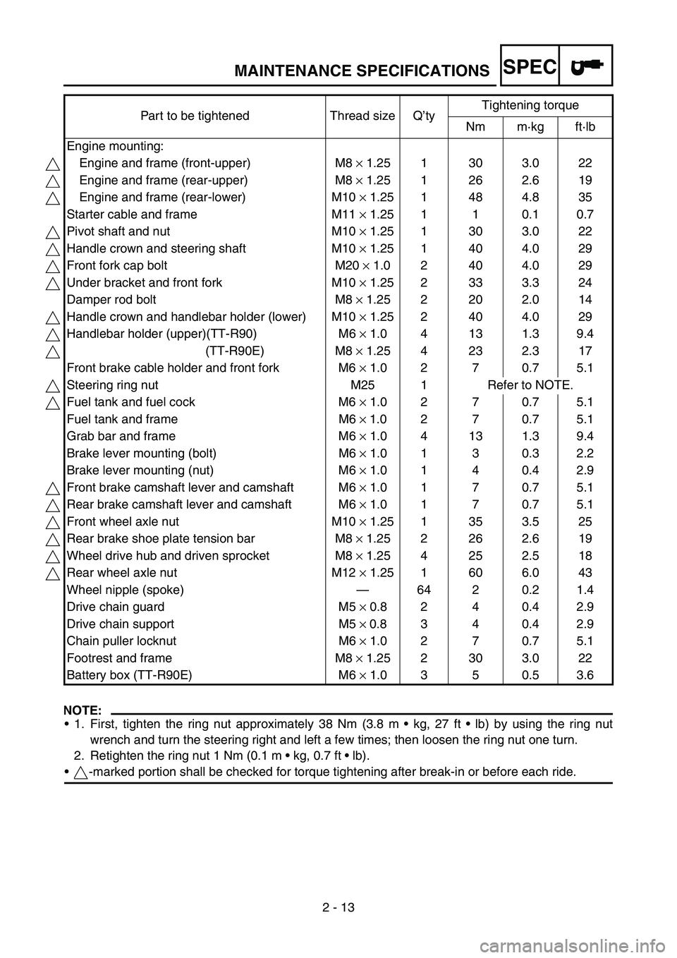
NOTE:
1. First, tighten the ring nut approximately 38 Nm (3.8 m kg, 27 ft lb) by using the ring nut
wrench and turn the steering right and left a few times; then loosen the ring nut one turn.
2. Retighten the ring nut 1 Nm (0.1 m kg, 0.7 ft lb).
-marked portion shall be checked for torque tightening after break-in or before each ride.Part to be tightened Thread size Q’tyTightening torque
Nm m·kg ft·lb
Engine mounting:
Engine and frame (front-upper) M8 × 1.25 1 30 3.0 22
Engine and frame (rear-upper) M8 × 1.25 1 26 2.6 19
Engine and frame (rear-lower) M10 × 1.25 1 48 4.8 35
Starter cable and frame M11 × 1.25 1 1 0.1 0.7
Pivot shaft and nut M10 × 1.25 1 30 3.0 22
Handle crown and steering shaft M10 × 1.25 1 40 4.0 29
Front fork cap bolt M20 × 1.0 2 40 4.0 29
Under bracket and front fork M10 × 1.25 2 33 3.3 24
Damper rod bolt M8 × 1.25 2 20 2.0 14
Handle crown and handlebar holder (lower) M10 × 1.25 2 40 4.0 29
Handlebar holder (upper)(TT-R90) M6 × 1.0 4 13 1.3 9.4
(TT-R90E) M8 × 1.25 4 23 2.3 17
Front brake cable holder and front fork M6 × 1.0 2 7 0.7 5.1
Steering ring nut M25 1 Refer to NOTE.
Fuel tank and fuel cock M6 × 1.0 2 7 0.7 5.1
Fuel tank and frame M6 × 1.0 2 7 0.7 5.1
Grab bar and frame M6 × 1.0 4 13 1.3 9.4
Brake lever mounting (bolt) M6 × 1.0 1 3 0.3 2.2
Brake lever mounting (nut) M6 × 1.0 1 4 0.4 2.9
Front brake camshaft lever and camshaft M6 × 1.0 1 7 0.7 5.1
Rear brake camshaft lever and camshaft M6 × 1.0 1 7 0.7 5.1
Front wheel axle nut M10 × 1.25 1 35 3.5 25
Rear brake shoe plate tension bar M8 × 1.25 2 26 2.6 19
Wheel drive hub and driven sprocket M8 × 1.25 4 25 2.5 18
Rear wheel axle nut M12 × 1.25 1 60 6.0 43
Wheel nipple (spoke)—64 2 0.2 1.4
Drive chain guard M5 × 0.8 2 4 0.4 2.9
Drive chain support M5 × 0.8 3 4 0.4 2.9
Chain puller locknut M6 × 1.0 2 7 0.7 5.1
Footrest and frame M8 × 1.25 2 30 3.0 22
Battery box (TT-R90E) M6 × 1.0 3 5 0.5 3.6
MAINTENANCE SPECIFICATIONS
Page 76 of 390
SPEC
2 - 17
EC220001
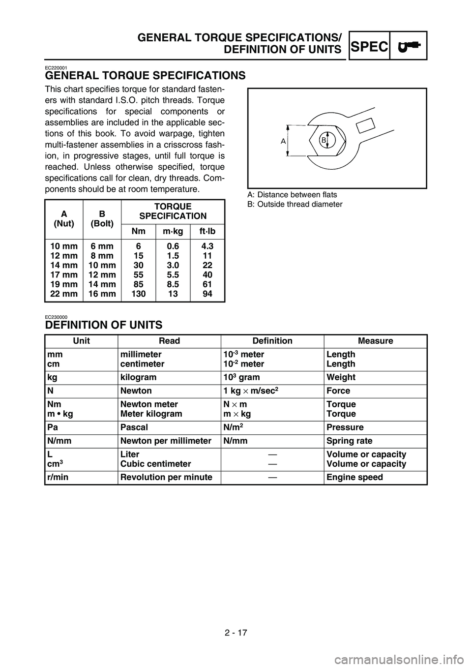
GENERAL TORQUE SPECIFICATIONS
This chart specifies torque for standard fasten-
ers with standard I.S.O. pitch threads. Torque
specifications for special components or
assemblies are included in the applicable sec-
tions of this book. To avoid warpage, tighten
multi-fastener assemblies in a crisscross fash-
ion, in progressive stages, until full torque is
reached. Unless otherwise specified, torque
specifications call for clean, dry threads. Com-
ponents should be at room temperature.
A: Distance between flats
B: Outside thread diameter
EC230000
DEFINITION OF UNITS
A
(Nut)B
(Bolt)TORQUE
SPECIFICATION
Nm m·kg ft·lb
10 mm
12 mm
14 mm
17 mm
19 mm
22 mm6 mm
8 mm
10 mm
12 mm
14 mm
16 mm6
15
30
55
85
1300.6
1.5
3.0
5.5
8.5
134.3
11
22
40
61
94
Unit Read Definition Measure
mm
cmmillimeter
centimeter10
-3 meter
10-2 meterLength
Length
kg kilogram 10
3 gram Weight
N Newton 1 kg
× m/sec
2 Force
Nm
m kgNewton meter
Meter kilogramN
× m
m
× kgTorque
Torque
Pa Pascal N/m
2Pressure
N/mm Newton per millimeter N/mm Spring rate
L
cm
3 Liter
Cubic centimeter—
—Volume or capacity
Volume or capacity
r/min Revolution per minute
—Engine speed
GENERAL TORQUE SPECIFICATIONS/
DEFINITION OF UNITS
Page 112 of 390
2 - 18
SPECCABLE ROUTING DIAGRAM
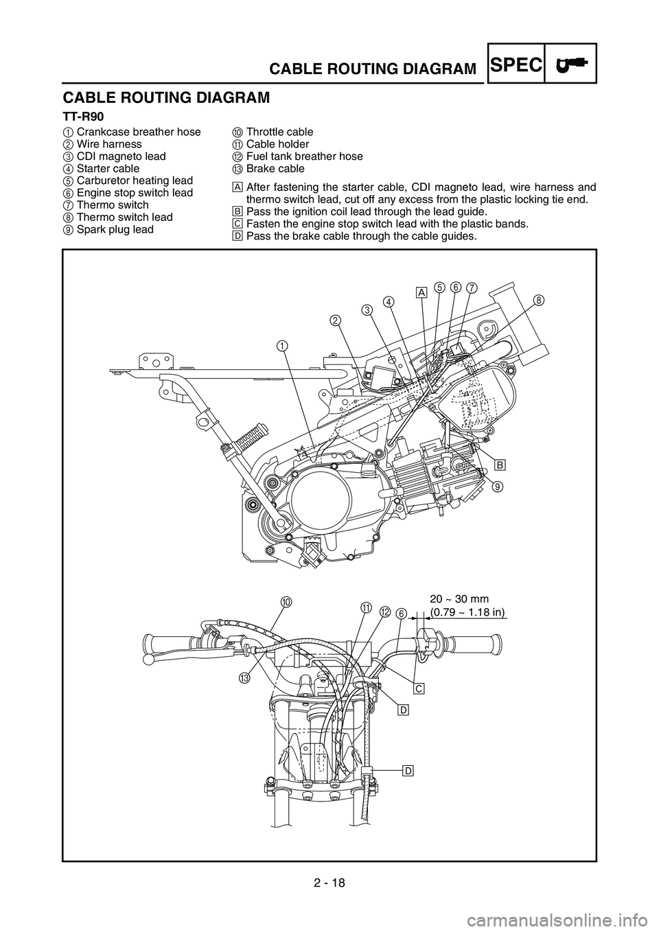
CABLE ROUTING DIAGRAM
TT-R90
1Crankcase breather hose
2Wire harness
3CDI magneto lead
4Starter cable
5Carburetor heating lead
6Engine stop switch lead
7Thermo switch
8Thermo switch lead
9Spark plug lead0Throttle cable
ACable holder
BFuel tank breather hose
CBrake cable
ÈAfter fastening the starter cable, CDI magneto lead, wire harness and
thermo switch lead, cut off any excess from the plastic locking tie end.
ÉPass the ignition coil lead through the lead guide.
ÊFasten the engine stop switch lead with the plastic bands.
ËPass the brake cable through the cable guides.
12345
9
0
B A
6
CÈ
É
Ê
Ë
Ë
67
8
20 ~ 30 mm
(0.79 ~ 1.18 in)
Page 114 of 390
2 - 19
SPECCABLE ROUTING DIAGRAM
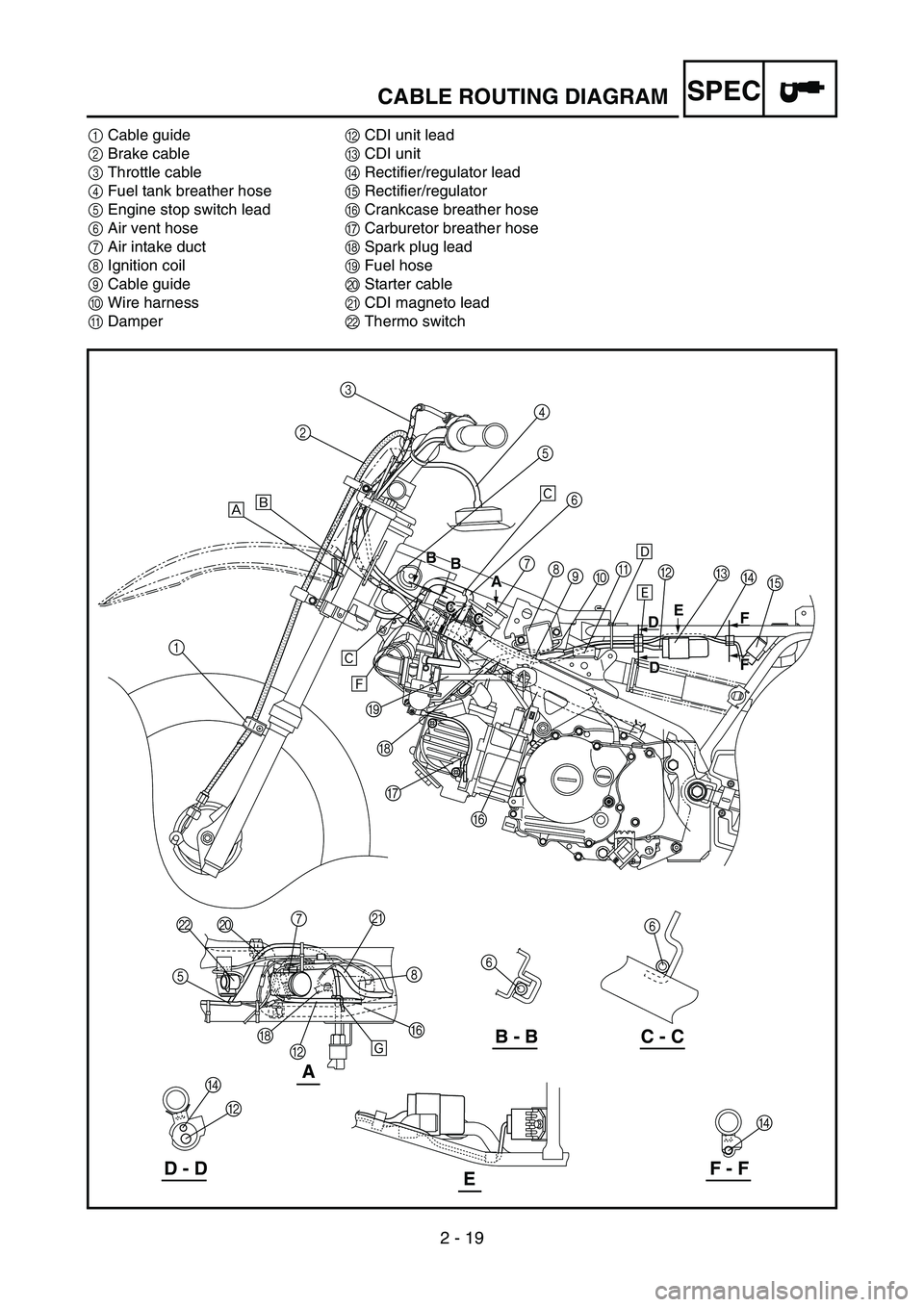
1Cable guide
2Brake cable
3Throttle cable
4Fuel tank breather hose
5Engine stop switch lead
6Air vent hose
7Air intake duct
8Ignition coil
9Cable guide
0Wire harness
ADamperBCDI unit lead
CCDI unit
DRectifier/regulator lead
ERectifier/regulator
FCrankcase breather hose
GCarburetor breather hose
HSpark plug lead
IFuel hose
JStarter cable
KCDI magneto lead
LThermo switch
A
123
4
5
6
7
8
9
0A
C
E B
F G H I
6
6 J L
5
H
B8
F K
7 ÈÊ
Ì
Ê
Í
ÎB - B C - C
D - DF - FE
É
Ë
D
D
B
D
A A B
B B
B
C
C C
CE
B D
B
D
F F F F