brake light YAMAHA TW125 2002 Owners Manual
[x] Cancel search | Manufacturer: YAMAHA, Model Year: 2002, Model line: TW125, Model: YAMAHA TW125 2002Pages: 88, PDF Size: 1.7 MB
Page 6 of 88

EAU00009
TABLE OF CONTENTS
GIVE SAFETY THE RIGHT OF WAY ............... 1-1
DESCRIPTION ................................................. 2-1
Left view ......................................................... 2-1
Right view ...................................................... 2-2
Controls and instruments ............................... 2-3
INSTRUMENT AND CONTROL FUNCTIONS . 3-1
Main switch .................................................... 3-1
Indicator lights ................................................ 3-1
Speedometer unit .......................................... 3-2
Handlebar switches ........................................ 3-2
Clutch lever .................................................... 3-4
Shift pedal ...................................................... 3-4
Brake lever ..................................................... 3-4
Brake pedal .................................................... 3-5
Fuel tank cap ................................................. 3-5
Fuel ................................................................ 3-6
Fuel cock ........................................................ 3-7
Starter (choke) knob ...................................... 3-8
Steering lock .................................................. 3-8
Seat ................................................................ 3-9
Helmet holder ................................................. 3-9
Shock absorber ............................................ 3-10
Carrier .......................................................... 3-10
Luggage strap holders ................................. 3-10
Sidestand ..................................................... 3-11Ignition circuit cut-off system ........................ 3-11
PRE-OPERATION CHECKS ............................ 4-1
Pre-operation check list ................................. 4-1
OPERATION AND IMPORTANT RIDING
POINTS ............................................................. 5-1
Starting the engine ......................................... 5-1
Starting a warm engine .................................. 5-2
Shifting ........................................................... 5-3
Recommended shift points
(for Switzerland only) .................................. 5-3
Tips for reducing fuel consumption ................ 5-4
Engine break-in .............................................. 5-4
Parking ........................................................... 5-5
PERIODIC MAINTENANCE AND MINOR
REPAIR ............................................................. 6-1
Owner’s tool kit .............................................. 6-1
Periodic maintenance and lubrication chart ... 6-2
Removing and installing panels ..................... 6-5
Checking the spark plug ................................ 6-7
Engine oil and oil filter element ...................... 6-9
Cleaning the air filter element and check
hose .......................................................... 6-12
Adjusting the carburetor ............................... 6-14
Adjusting the engine idling speed ................ 6-14
123
456
5RS-9-E0 (TW125) 7/30/01 6:02 PM Page 5
Page 7 of 88

Adjusting the throttle cable free play ............ 6-15
Adjusting the valve clearance ...................... 6-16
Tires ............................................................. 6-16
Spoke wheels ............................................... 6-18
Adjusting the clutch lever free play .............. 6-19
Adjusting the brake lever free play ............... 6-20
Adjusting the brake pedal position and
free play .................................................... 6-21
Adjusting the rear brake light switch ............ 6-22
Checking the front brake pads and
rear brake shoes ....................................... 6-23
Checking the brake fluid level ...................... 6-24
Changing the brake fluid .............................. 6-25
Drive chain slack .......................................... 6-25
Lubricating the drive chain ........................... 6-27
Checking and lubricating the cables ............ 6-27
Checking and lubricating the throttle grip
and cable .................................................. 6-28
Checking and lubricating the brake and
shift pedals ................................................ 6-28
Checking and lubricating the brake and
clutch levers .............................................. 6-29
Checking and lubricating the sidestand ....... 6-29
Lubricating the rear suspension ................... 6-30
Checking the front fork ................................. 6-30
Checking the steering .................................. 6-31
Checking the wheel bearings ....................... 6-31Battery .......................................................... 6-32
Replacing the fuse ....................................... 6-33
Replacing the headlight bulb ........................ 6-34
Replacing a turn signal light bulb ................. 6-36
Replacing the tail/brake light bulb ................ 6-36
Supporting the motorcycle ........................... 6-37
Front wheel .................................................. 6-38
Rear wheel ................................................... 6-40
Troubleshooting ........................................... 6-42
Troubleshooting chart .................................. 6-43
MOTORCYCLE CARE AND STORAGE .......... 7-1
Care ............................................................... 7-1
Storage .......................................................... 7-4
SPECIFICATIONS ............................................ 8-1
Conversion table ............................................ 8-5
CONSUMER INFORMATION ........................... 9-1
Identification numbers .................................... 9-1
Key identification number ............................... 9-1
Vehicle identification number ......................... 9-1
Model label ..................................................... 9-2
TABLE OF CONTENTS
789
5RS-9-E0 (TW125) 7/30/01 6:02 PM Page 6
Page 11 of 88

2-3
DESCRIPTION
2
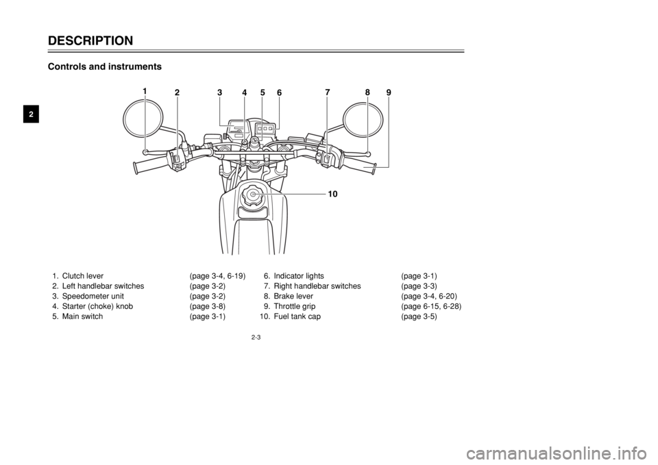
Controls and instruments1. Clutch lever (page 3-4, 6-19)
2. Left handlebar switches (page 3-2)
3. Speedometer unit (page 3-2)
4. Starter (choke) knob (page 3-8)
5. Main switch (page 3-1)6. Indicator lights (page 3-1)
7. Right handlebar switches (page 3-3)
8. Brake lever (page 3-4, 6-20)
9. Throttle grip (page 6-15, 6-28)
10. Fuel tank cap (page 3-5)
1
23
45
678
9
10
5RS-9-E0 (TW125) 7/30/01 6:02 PM Page 10
Page 35 of 88

6-4
PERIODIC MAINTENANCE AND MINOR REPAIR
6
EAU03541
NOTE:
8The air filter needs more frequent service if you are riding in unusually wet or dusty areas.
8Hydraulic brake service
9Regularly check and, if necessary, correct the brake fluid level.
9Every two years replace the internal components of the brake master cylinder and caliper, and change the brake
fluid.
9Replace the brake hoses every four years and if cracked or damaged.21
*Carburetor•Check starter (choke) operation.
•Adjust engine idling speed.√√√√√ √
22 Engine oil•Change.
•Check oil level and vehicle for oil leakage.√√√√√ √
23 Engine oil filter element•Clean.√√√
24*Engine oil strainer•Clean.√
25*Front and rear brake
switches•Check operation.√√√√√ √
26 Moving parts and cables•Lubricate.√√√√ √
27*Lights, signals and
switches•Check operation.
•Adjust headlight beam.√√√√√ √ NO. ITEM CHECK OR MAINTENANCE JOBODOMETER READING (× 1,000 km)
ANNUAL
CHECK
1 6 12 18 24
5RS-9-E0 (TW125) 7/30/01 6:03 PM Page 34
Page 53 of 88

6-22
PERIODIC MAINTENANCE AND MINOR REPAIR
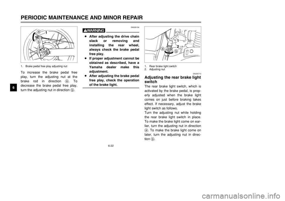
6To increase the brake pedal free
play, turn the adjusting nut at the
brake rod in direction a. To
decrease the brake pedal free play,
turn the adjusting nut in direction b.
ba
1
1. Brake pedal free play adjusting nut
EAU00713
Adjusting the rear brake light
switchThe rear brake light switch, which is
activated by the brake pedal, is prop-
erly adjusted when the brake light
comes on just before braking takes
effect. If necessary, adjust the brake
light switch as follows.
Turn the adjusting nut while holding
the rear brake light switch in place.
To make the brake light come on ear-
lier, turn the adjusting nut in direction
a. To make the brake light come on
later, turn the adjusting nut in direc-
tion b.
1
2
a
b
1. Rear brake light switch
2. Adjusting nut
EW000106
w8After adjusting the drive chain
slack or removing and
installing the rear wheel,
always check the brake pedal
free play.
8If proper adjustment cannot be
obtained as described, have a
Yamaha dealer make this
adjustment.
8After adjusting the brake pedal
free play, check the operation
of the brake light.
5RS-9-E0 (TW125) 7/30/01 6:03 PM Page 52
Page 57 of 88

6-26
PERIODIC MAINTENANCE AND MINOR REPAIR
6
EAU04369
To adjust the drive chain slack
1. Loosen the brake pedal free play
adjusting nut.
2. Loosen the axle nut.
3. To tighten the drive chain, turn
the adjusting plate on each side
of the swingarm in direction a.
To loosen the drive chain, turn
the adjusting plate on each side
of the swingarm in direction b,
and then push the rear wheel for-
ward.
NOTE:
Make sure that both adjusting plates
are in the same position for proper
wheel alignment.
EC000096
cCImproper drive chain slack will
overload the engine as well as
other vital parts of the motorcycle
and can lead to chain slippage or
breakage. To prevent this from
occurring, keep the drive chain
slack within the specified limits.4. Tighten the axle nut to the speci-
fied torque.5. Adjust the brake pedal free play.
(See page 6-21 for brake pedal
free play adjustment proce-
dures.)
EW000103
wAfter adjusting the brake pedal
free play, check the operation of
the brake light.
32
a
b
1
1. Brake pedal free play adjusting nut
2. Axle nut
3. Drive chain adjusting plate
Tightening torque:
Axle nut:
90 Nm (9.0 m·kgf)
5RS-9-E0 (TW125) 7/30/01 6:03 PM Page 56
Page 67 of 88

6-36
PERIODIC MAINTENANCE AND MINOR REPAIR
6
EAU03497
Replacing a turn signal light
bulb1. Remove the turn signal light lens
by removing the screw.
2. Remove the defective bulb by
pushing it in and turning it coun-
terclockwise.
3. Insert a new bulb into the socket,
push it in, and then turn it clock-
wise until it stops.
4. Install the lens by installing the
screw.
1
2
3
1. Screw
2. Lens
3. bulb
EAU01623
Replacing the tail/brake light
bulb1. Remove the tail/brake light lens
by removing the screws.
1
1. Screw (×2)
ECA00065
cCDo not overtighten the screw, oth-
erwise the lens may break.
5RS-9-E0 (TW125) 7/30/01 6:03 PM Page 66
Page 73 of 88

6-42
PERIODIC MAINTENANCE AND MINOR REPAIR
6
EW000103
wAfter adjusting the brake pedal
free play, check the operation of
the brake light.
EAU01008
TroubleshootingAlthough Yamaha motorcycles
receive a thorough inspection before
shipment from the factory, trouble
may occur during operation. Any
problem in the fuel, compression, or
ignition systems, for example, can
cause poor starting and loss of
power.
The following troubleshooting chart
represents a quick and easy proce-
dure for checking these vital systems
yourself. However, should your
motorcycle require any repair, take it
to a Yamaha dealer, whose skilled
technicians have the necessary tools,
experience, and know-how to service
the motorcycle properly.
Use only genuine Yamaha replace-
ment parts. Imitation parts may look
like Yamaha parts, but they are often
inferior, have a shorter service life
and can lead to expensive repair
bills.
5RS-9-E0 (TW125) 7/30/01 6:03 PM Page 72
Page 76 of 88

7-2
MOTORCYCLE CARE AND STORAGE
7 8Do not use any harsh chemical
products on plastic parts. Be
sure to avoid using cloths or
sponges which have been in
contact with strong or abra-
sive cleaning products, sol-
vent or thinner, fuel (gasoline),
rust removers or inhibitors,
brake fluid, antifreeze or elec-
trolyte.
8Do not use high-pressure
washers or steam-jet cleaners
since they cause water seep-
age and deterioration in the
following areas: seals (of
wheel and swingarm bearings,
fork and brakes), electric com-
ponents (couplers, connec-
tors, instruments, switches
and lights), breather hoses
and vents.8For motorcycles equipped
with a windshield: Do not use
strong cleaners or hard
sponges as they will cause
dulling or scratching. Some
cleaning compounds for plas-
tic may leave scratches on the
windshield. Test the product
on a small hidden part of the
windshield to make sure that it
does not leave any marks. If
the windshield is scratched,
use a quality plastic polishing
compound after washing.
After normal useRemove dirt with warm water, a mild
detergent, and a soft, clean sponge,
and then rinse thoroughly with clean
water. Use a toothbrush or bottle-
brush for hard-to-reach areas.
Stubborn dirt and insects will come
off more easily if the area is covered
with a wet cloth for a few minutes
before cleaning.After riding in the rain, near the sea
or on salt-sprayed roadsSince sea salt or salt sprayed on
roads during winter are extremely
corrosive in combination with water,
carry out the following steps after
each ride in the rain, near the sea or
on salt-sprayed roads.NOTE:
Salt sprayed on roads in the winter
may remain well into spring.1. Clean the motorcycle with cold
water and a mild detergent, after
the engine has cooled down.
ECA00012
cCDo not use warm water since it
increases the corrosive action of
the salt.2. Apply a corrosion protection
spray on all metal, including
chrome- and nickel-plated, sur-
faces to prevent corrosion.
5RS-9-E0 (TW125) 7/30/01 6:03 PM Page 75
Page 83 of 88

8-4
SPECIFICATIONS
8
Electrical
Ignition system C.D.I.
Charging system
Type A.C. magneto
Standard output 14 V, 170W @ 5,000 r/min
Battery
Type GT6B-3
Voltage, capacity 12 V, 6 Ah
Headlight bulb typeHalogen bulb
Bulb voltage, wattage ×quantity
Headlight 12 V, 60/55 W ×1
Tail/brake light 12 V, 5/21 W ×1
Front turn signal light 12 V, 21 W ×2
Rear turn signal light 12 V, 21 W ×2
Auxiliary light 12 V, 4 W ×1
Meter lighting 12 V, 3.4 W ×1
Neutral indicator light 12 V, 3.4 W ×1
High beam indicator light 12 V, 3.4 W ×1
Turn indicator light 12 V, 3.4 W ×1
Fuse20 A
5RS-9-E0 (TW125) 7/30/01 6:03 PM Page 82