YAMAHA VIKING 2015 Owner's Guide
Manufacturer: YAMAHA, Model Year: 2015, Model line: VIKING, Model: YAMAHA VIKING 2015Pages: 182, PDF Size: 3.82 MB
Page 31 of 182
3-1
1
23
4
5
6
7
8
9
10
11
12
13
14
EVU00080
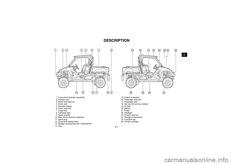
1-DESCRIPTION
1. Front shock absorber assembly
2. Radiator cap
3. Brake fluid reservoir
4. Driver seat
5. Shoulder bolster
6. Driver seat belt
7. Cargo bed
8. Tail/brake light
9. Spark arrester
10. Rear shock absorber assembly
11. Spark plug
12. Cargo bed release lever
13. Storage compartment (for YXM700PSF)
14. Door 15. Engine oil dipstick
16. Passenger seat belt
17. Passenger seat
18. Sun top (for sun top models)
19. Air filter
20. Battery
21. Fuses
22. Headlight
23. Coolant reservoir
24. Storage compartment
25. Fuel tank cap
26. Oil filter cartridge13
8
7
90AB
D
C 64
2
5
PO
NM J
HK
IGFE
L
1XP7C_EE.book Page 1 Monday, June 9, 2014 5:17 PM
Page 32 of 182
3-2
3
4
5
6
7
8
9
10
11
12
13
14
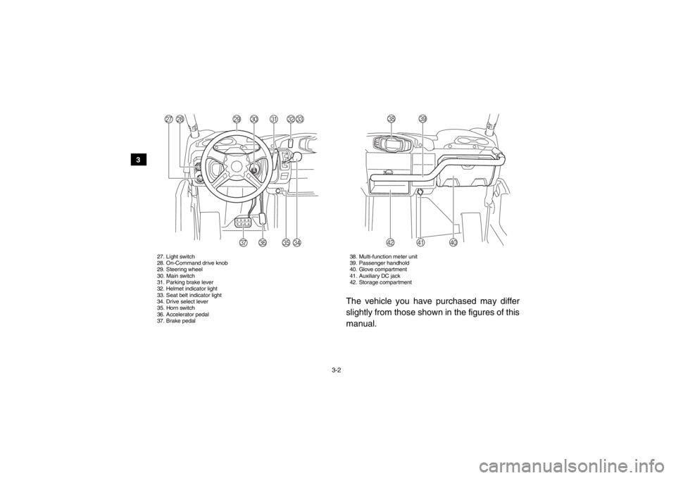
27. Light switch
28. On-Command drive knob
29. Steering wheel
30. Main switch
31. Parking brake lever
32. Helmet indicator light
33. Seat belt indicator light
34. Drive select lever
35. Horn switch
36. Accelerator pedal
37. Brake pedal 38. Multi-function meter unit
39. Passenger handhold
40. Glove compartment
41. Auxiliary DC jack
42. Storage compartment
The vehicle you have purchased may differ
slightly from those shown in the figures of this
manual.
[
Z
R
S
T
U
Y
Q
VWX
b
^
\
]a
1XP7C_EE.book Page 2 Monday, June 9, 2014 5:17 PM
Page 33 of 182
4-1
1
2
34
5
6
7
8
9
10
11
12
13
14
EVU00130
1-INSTRUMENT AND CONTROL FUNCTIONS
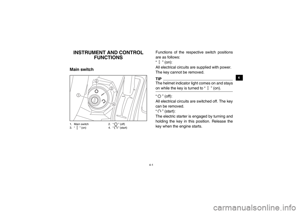
EVU00140Main switch1. Main switch 2. “ ” (off)
3. “ ” (on) 4. “ ” (start)
Functions of the respective switch positions
are as follows:
“ ” (on):
All electrical circuits are supplied with power.
The key cannot be removed.TIPThe helmet indicator light comes on and stays
on while the key is turned to “ ” (on).“ ” (off):
All electrical circuits are switched off. The key
can be removed.
“ ” (start):
The electric starter is engaged by turning and
holding the key in this position. Release the
key when the engine starts.
1
2
34
1XP7C_EE.book Page 1 Monday, June 9, 2014 5:17 PM
Page 34 of 182

4-2
4
5
6
7
8
9
10
11
12
13
14
EVU00150Indicator lights and warning lights1. On-Command differential gear lock indicator light “DIFF. LOCK”
2. Low-range indicator light “L”
3. High-range indicator light “H”
4. Neutral indicator light “N”
5. Reverse indicator light “R”
6. Parking brake indicator light “ ”
7. On-Command four-wheel-drive/differential gear lock indicator “ ”/“ ”
8. Engine trouble warning light “ ”
9. Coolant temperature warning light “ ”
10. Electric Power Steering warning light “EPS” 1. Helmet indicator light “ ”
2. Seat belt indicator light “ ”
EVU01140Low-range indicator light “L”
This indicator light comes on when the drive
select lever is in the “L” position.EVU01150High-range indicator light “H”
This indicator light comes on when the drive
select lever is in the “H” position.
356421
7
809
DIFF.
LOCK
21
1XP7C_EE.book Page 2 Monday, June 9, 2014 5:17 PM
Page 35 of 182
4-3
1
2
34
5
6
7
8
9
10
11
12
13
14
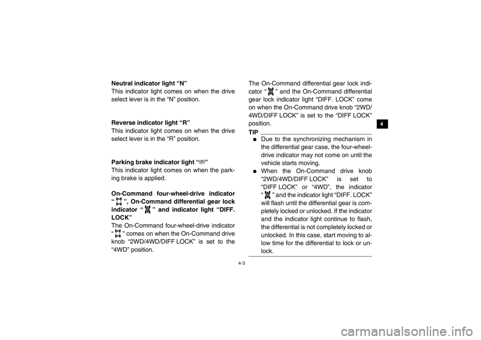
EVU00170Neutral indicator light “N”
This indicator light comes on when the drive
select lever is in the “N” position.5B410001Reverse indicator light “R”
This indicator light comes on when the drive
select lever is in the “R” position.EVU00210Parking brake indicator light “ ”
This indicator light comes on when the park-
ing brake is applied.EBU29621On-Command four-wheel-drive indicator
“ ”, On-Command differential gear lock
indicator “ ” and indicator light “DIFF.
LOCK”
The On-Command four-wheel-drive indicator
“ ” comes on when the On-Command drive
knob “2WD/4WD/DIFF LOCK” is set to the
“4WD” position.The On-Command differential gear lock indi-
cator “ ” and the On-Command differential
gear lock indicator light “DIFF. LOCK” come
on when the On-Command drive knob “2WD/
4WD/DIFF LOCK” is set to the “DIFF LOCK”
position.
TIP●
Due to the synchronizing mechanism in
the differential gear case, the four-wheel-
drive indicator may not come on until the
vehicle starts moving.
●
When the On-Command drive knob
“2WD/4WD/DIFF LOCK” is set to
“DIFF LOCK” or “4WD”, the indicator
“ ” and the indicator light “DIFF. LOCK”
will flash until the differential gear is com-
pletely locked or unlocked. If the indicator
and the indicator light continue to flash,
the differential is not completely locked or
unlocked. In this case, start moving to al-
low time for the differential to lock or un-
lock.
DIFF.
LOCK
DIFF.
LOCKDIFF.
LOCK
1XP7C_EE.book Page 3 Monday, June 9, 2014 5:17 PM
Page 36 of 182
4-4
4
5
6
7
8
9
10
11
12
13
14
5B410002Coolant temperature warning light “ ”
If the coolant temperature reaches a specific
level, this light comes on to warn that the cool-
ant temperature is too hot. If the light comes
on during operation, stop the engine as soon
as it is safe to do so and allow the engine to
cool down for about 10 minutes.
(See page 8-58.)
The electrical circuit of the warning light can
be checked by turning the key to “ ” (on). If
the warning light does not come on initially
when the key is turned to “ ” (on), or if the
warning light remains on, have a Yamaha
dealer check the electrical circuit.
NOTICE●
The engine may overheat if the vehicle
is overloaded. If this happens, reduce
the load to specification.
●
After restarting, make sure that the
warning light is out. Continuous use
while this warning light is on may
cause damage to the engine.
1XP7C_EE.book Page 4 Monday, June 9, 2014 5:17 PM
Page 37 of 182
4-5
1
2
34
5
6
7
8
9
10
11
12
13
14
5B410003Engine trouble warning light “ ”
This warning light comes on or flashes if a
problem is detected in the electrical circuit
monitoring the engine. When this occurs,
have a Yamaha dealer check the self-diagno-
sis system. (See page 4-11 for an explanation
of the self-diagnosis device.)
The electrical circuit of the warning light can
be checked by turning the key to “ ” (on). If
the warning light does not come on initially
when the key is turned to “ ” (on), or if the
warning light remains on, have a Yamaha
dealer check the electrical circuit.Electric Power Steering warning light
“EPS”
This warning light comes on when the key is
turned to “ ” (on), and then goes off once
the engine is started. If the warning light re-
mains on or comes on after the engine is
started, the EPS system may not be working
correctly. When this occurs, have a Yamaha
dealer check the EPS system.
The electrical circuit of the warning light can
be checked by turning the key to “ ” (on). If
the warning light does not come on, have a
Yamaha dealer check the electrical circuit.
TIPIf the steering load is too heavy (i.e., exces-
sive steering use when the Viking is traveling
at a slow speed), the power assist is reduced
to protect the EPS motor from overheating.
1XP7C_EE.book Page 5 Monday, June 9, 2014 5:17 PM
Page 38 of 182
4-6
4
5
6
7
8
9
10
11
12
13
14
Helmet indicator light “ ”
The indicator light comes on and stays on
while the key is turned to “ ” (on) to remind
the occupants to always wear a helmet. If the
indicator light does not come on when the key
is turned to “ ” (on), have a Yamaha dealer
check the electrical circuit.
Seat belt indicator light “ ”
The indicator light comes on when the key is
turned to “ ” (on) to remind the occupants to
fasten their seat belt. The indicator light stays
on until the driver seat belt is properly latched.
If the indicator light does not come on when
the key is turned to “ ” (on), or if the indica-
tor light remains on after the driver seat belt is
properly latched, have a Yamaha dealer
check the electrical circuit.
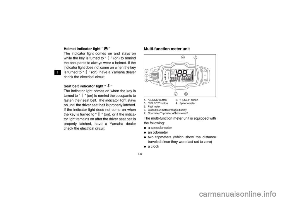
5B410004Multi-function meter unit1. “CLOCK” button 2. “RESET” button
3. “SELECT” button 4. Speedometer
5. Fuel meter
6. Clock/Hour meter/Voltage display
7. Odometer/Tripmeter A/Tripmeter BThe multi-function meter unit is equipped with
the following:●
a speedometer
●
an odometer
●
two tripmeters (which show the distance
traveled since they were last set to zero)
●
a clock321
4
5
6
7
1XP7C_EE.book Page 6 Monday, June 9, 2014 5:17 PM
Page 39 of 182
4-7
1
2
34
5
6
7
8
9
10
11
12
13
14
●
an hour meter (which shows the total time
the engine has been running)
●
a voltage display (which shows the battery
voltage)
●
a fuel meter
●
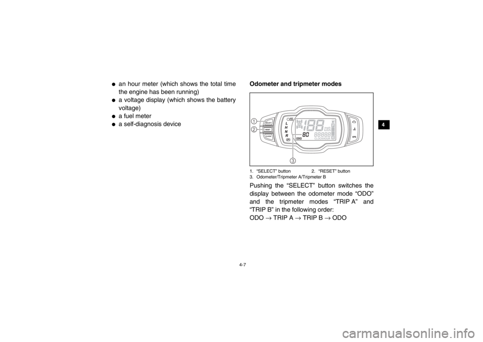
a self-diagnosis deviceOdometer and tripmeter modes
1. “SELECT” button 2. “RESET” button
3. Odometer/Tripmeter A/Tripmeter BPushing the “SELECT” button switches the
display between the odometer mode “ODO”
and the tripmeter modes “TRIP A” and
“TRIP B” in the following order:
ODO
→ TRIP A → TRIP B → ODO12
3
1XP7C_EE.book Page 7 Monday, June 9, 2014 5:17 PM
Page 40 of 182
4-8
4
5
6
7
8
9
10
11
12
13
14
To reset a tripmeter, select it by pushing the
“SELECT” button, and then push the “RE-
SET” button for at least three seconds. The
tripmeters can be used to estimate the dis-
tance that can be traveled with a full tank of fu-
el. This information enables you to plan future
fuel stops.TIPTo switch the display between “mph” and
“km/h”, turn the key to “ ” (off), then push
and hold the “SELECT” button while turning
the key to “ ” (on).
Clock, hour meter and voltage display
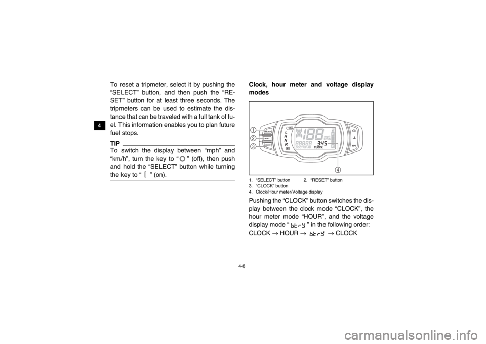
modes1. “SELECT” button 2. “RESET” button
3. “CLOCK” button
4. Clock/Hour meter/Voltage displayPushing the “CLOCK” button switches the dis-
play between the clock mode “CLOCK”, the
hour meter mode “HOUR”, and the voltage
display mode “ ” in the following order:
CLOCK → HOUR → → CLOCK
4
123
1XP7C_EE.book Page 8 Monday, June 9, 2014 5:17 PM