service YAMAHA VX110 2005 Service Manual
[x] Cancel search | Manufacturer: YAMAHA, Model Year: 2005, Model line: VX110, Model: YAMAHA VX110 2005Pages: 347, PDF Size: 14.17 MB
Page 318 of 347

8-25
E
HULL
HOOD
REMOTE CONTROL CABLES AND
SPEED SENSOR LEAD
EXPLODED DIAGRAM
Step Procedure/Part name Q’ty Service points
14 Shift cable end 1 Deluxe model only
15 Grommet 1 Deluxe model only
16 Nut 1 Deluxe model only
17 Shift cable 1 Deluxe model only
18 Seal 1 Deluxe model only
Reverse the removal steps for installation.
ProCarManuals.com
Page 319 of 347

8-26
E
HULL
HOOD
REMOTE CONTROL CABLES AND
SPEED SENSOR LEAD
SERVICE POINTS
WARNING
When routing the cables, do not grasp the
cable by the outer crimped sheath or steel
end. This could deform or loosen the cable
end due to extreme angles and or pressure.
Always hold the cables by the outer cover
below the crimp.
If a cable becomes damaged replace it.
Never attempt to repair a damaged cable.
Remote control cables inspection
1. Inspect:
Steering cable
Shift cable (Deluxe model only)
Frays/kinks/rough movement →
Replace.
Steering cable (jet pump end) installation
1. Install:
Steering cable
WARNING
The steering cable must be screwed in at
least 8 mm (0.31 in).
Steering cable set length
a
(jet pump end):
14.5 mm (0.57 in)
Steering cable stopper installation
1. Install:
Steering cable stopper
WARNING
Be sure to the steering cable stopper into
the groove in the outer cable as shown in
the illustration.
ProCarManuals.com
Page 321 of 347
8-28
E
HULL
HOODSEAT AND HAND GRIP
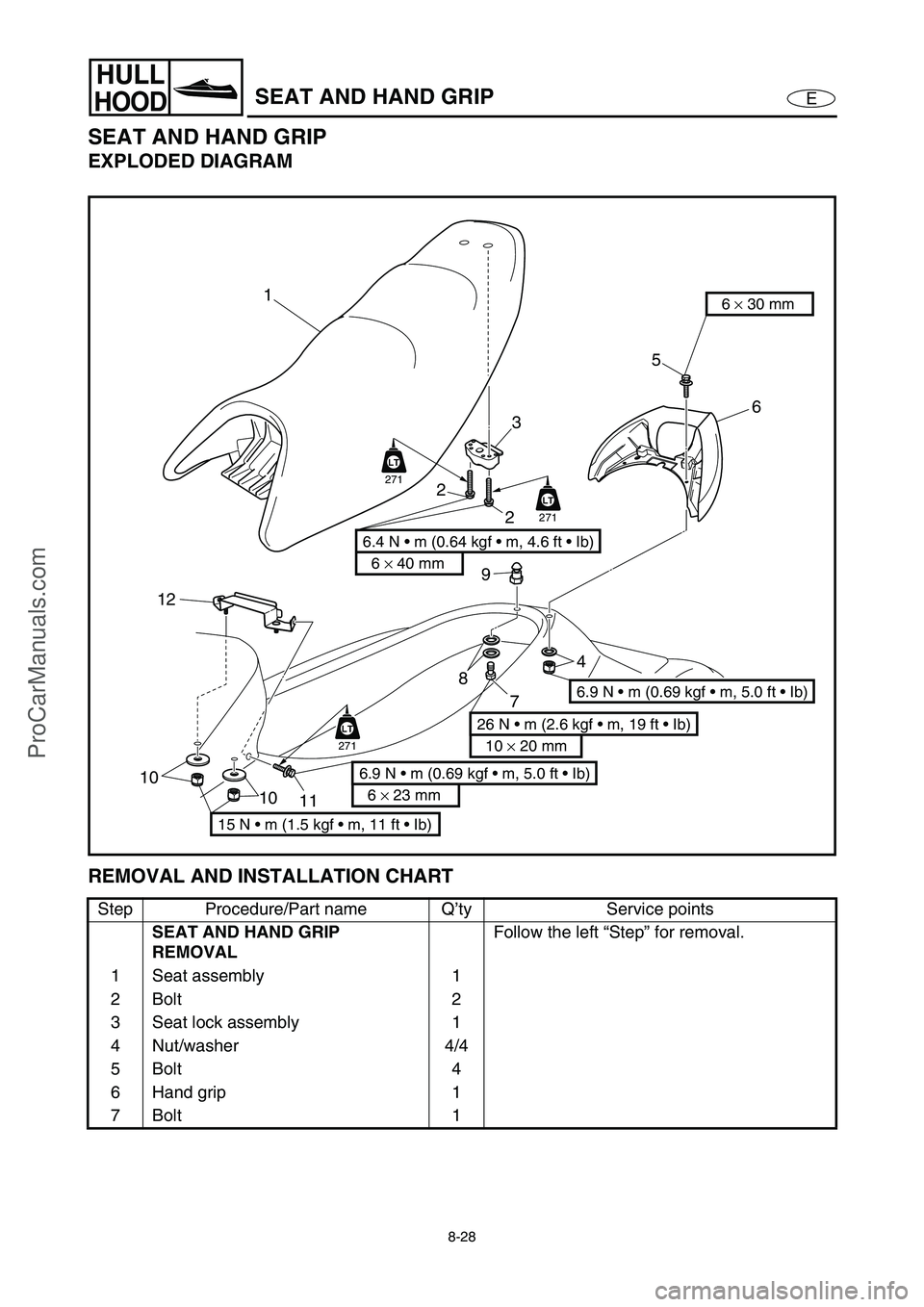
SEAT AND HAND GRIP
EXPLODED DIAGRAM
REMOVAL AND INSTALLATION CHART
Step Procedure/Part name Q’ty Service points
SEAT AND HAND GRIP
REMOVALFollow the left “Step” for removal.
1 Seat assembly 1
2Bolt 2
3 Seat lock assembly 1
4 Nut/washer 4/4
5Bolt 4
6 Hand grip 1
7Bolt 1
10
11 10
12
8
4
2
3
9
7
5
6
1
6 × 40 mm
6.4 N • m (0.64 kgf • m, 4.6 ft • Ib)
2
6 × 30 mm
6.9 N • m (0.69 kgf • m, 5.0 ft • Ib)
6 × 23 mm
6.9 N • m (0.69 kgf • m, 5.0 ft • Ib)
15 N • m (1.5 kgf • m, 11 ft • Ib)
10 × 20 mm
26 N • m (2.6 kgf • m, 19 ft • Ib)
LT
271
LT
271
LT
271
ProCarManuals.com
Page 322 of 347
8-29
E
HULL
HOODSEAT AND HAND GRIP
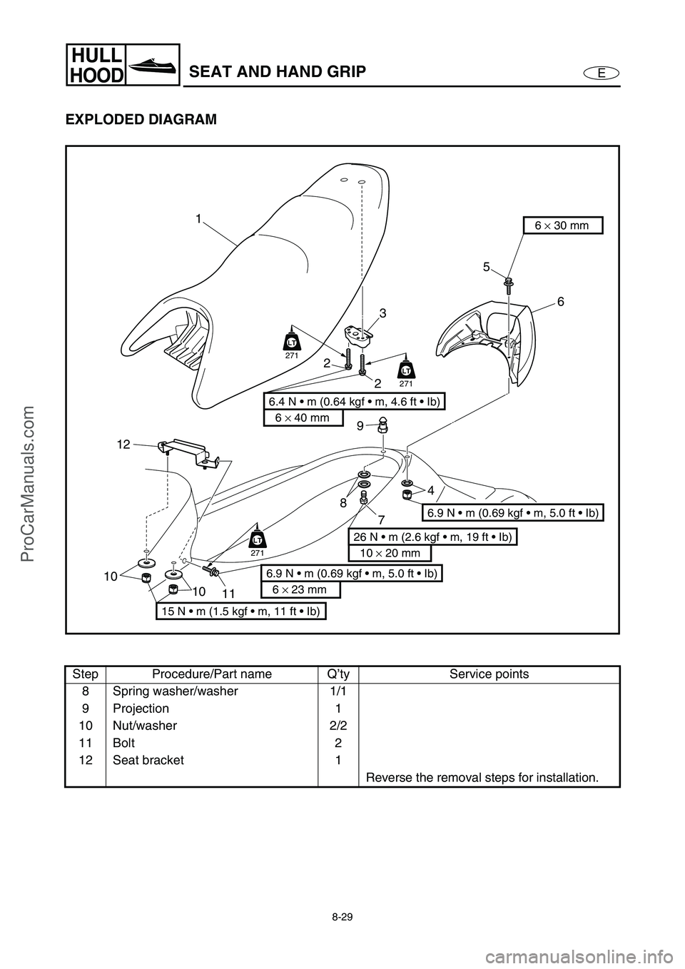
EXPLODED DIAGRAM
Step Procedure/Part name Q’ty Service points
8 Spring washer/washer 1/1
9 Projection 1
10 Nut/washer 2/2
11 Bolt 2
12 Seat bracket 1
Reverse the removal steps for installation.
10
11 10
12
8
4
2
3
9
7
5
6
1
6 × 40 mm
6.4 N • m (0.64 kgf • m, 4.6 ft • Ib)
2
6 × 30 mm
6.9 N • m (0.69 kgf • m, 5.0 ft • Ib)
6 × 23 mm
6.9 N • m (0.69 kgf • m, 5.0 ft • Ib)
15 N • m (1.5 kgf • m, 11 ft • Ib)
10 × 20 mm
26 N • m (2.6 kgf • m, 19 ft • Ib)
LT
271
LT
271
LT
271
ProCarManuals.com
Page 323 of 347
8-30
E
HULL
HOODSEAT AND HAND GRIP
SERVICE POINTS
Seat lock assembly inspection
1. Inspect:
Seat lock assembly
Damage/wear →
Replace.
ProCarManuals.com
Page 324 of 347
8-31
E
HULL
HOODEXHAUST SYSTEM
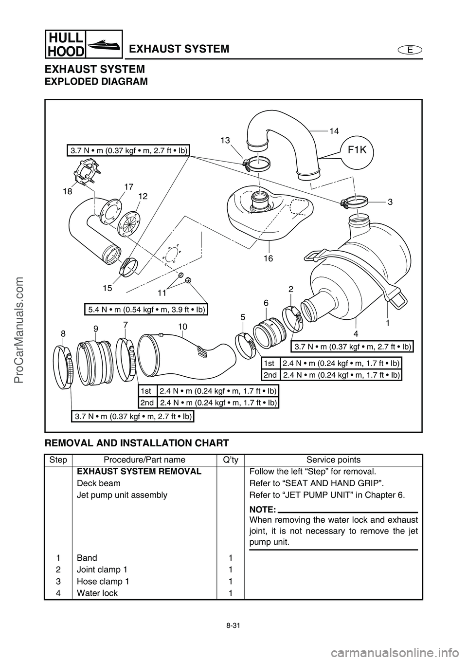
EXHAUST SYSTEM
EXPLODED DIAGRAM
REMOVAL AND INSTALLATION CHART
Step Procedure/Part name Q’ty Service points
EXHAUST SYSTEM REMOVAL
Follow the left “Step” for removal.
Deck beam Refer to “SEAT AND HAND GRIP”.
Jet pump unit assembly Refer to “JET PUMP UNIT” in Chapter 6.
NOTE:
When removing the water lock and exhaust
joint, it is not necessary to remove the jet
pump unit.
1 Band 1
2 Joint clamp 1 1
3 Hose clamp 1 1
4 Water lock 1
3
1 2
6
7
9
85
4 14
13
15 1817
12
1116
10
F1K3.7 N • m (0.37 kgf • m, 2.7 ft • Ib)
5.4 N • m (0.54 kgf • m, 3.9 ft • Ib)
3.7 N • m (0.37 kgf • m, 2.7 ft • Ib)
3.7 N • m (0.37 kgf • m, 2.7 ft • Ib)
2nd 2.4 N • m (0.24 kgf • m, 1.7 ft • Ib) 1st 2.4 N • m (0.24 kgf • m, 1.7 ft • Ib)
2nd 2.4 N • m (0.24 kgf • m, 1.7 ft • Ib) 1st 2.4 N • m (0.24 kgf • m, 1.7 ft • Ib)
ProCarManuals.com
Page 325 of 347
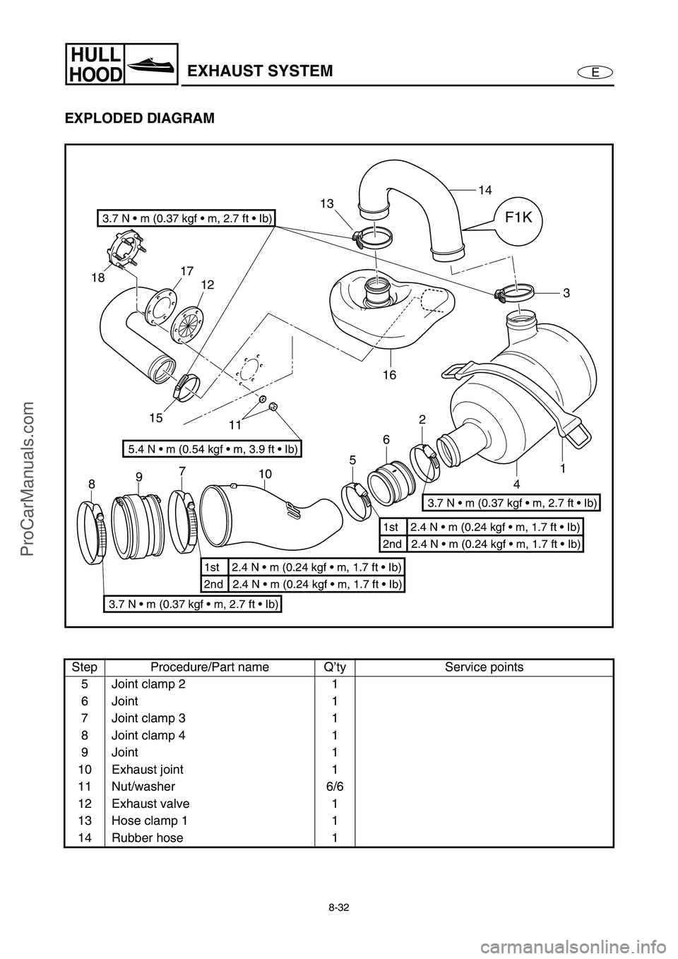
8-32
E
HULL
HOODEXHAUST SYSTEM
EXPLODED DIAGRAM
Step Procedure/Part name Q’ty Service points
5 Joint clamp 2 1
6 Joint 1
7 Joint clamp 3 1
8 Joint clamp 4 1
9 Joint 1
10 Exhaust joint 1
11 Nut/washer 6/6
12 Exhaust valve 1
13 Hose clamp 1 1
14 Rubber hose 1
3
1 2
6
7
9
85
4 14
13
15 1817
12
1116
10
F1K3.7 N • m (0.37 kgf • m, 2.7 ft • Ib)
5.4 N • m (0.54 kgf • m, 3.9 ft • Ib)
3.7 N • m (0.37 kgf • m, 2.7 ft • Ib)
3.7 N • m (0.37 kgf • m, 2.7 ft • Ib)
2nd 2.4 N • m (0.24 kgf • m, 1.7 ft • Ib) 1st 2.4 N • m (0.24 kgf • m, 1.7 ft • Ib)
2nd 2.4 N • m (0.24 kgf • m, 1.7 ft • Ib) 1st 2.4 N • m (0.24 kgf • m, 1.7 ft • Ib)
ProCarManuals.com
Page 326 of 347
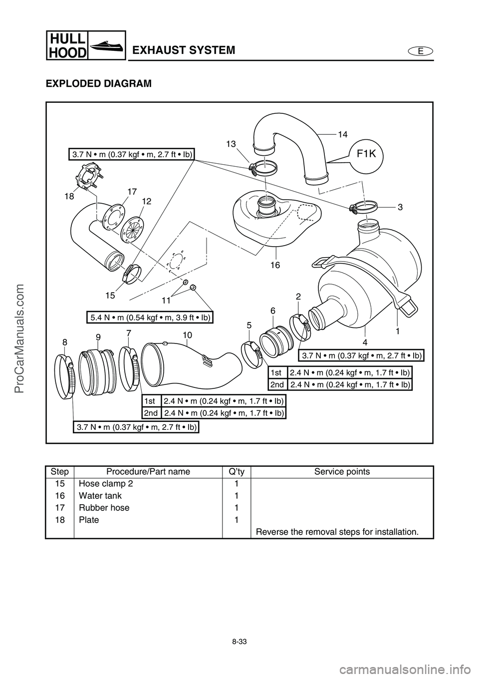
8-33
E
HULL
HOODEXHAUST SYSTEM
EXPLODED DIAGRAM
Step Procedure/Part name Q’ty Service points
15 Hose clamp 2 1
16 Water tank 1
17 Rubber hose 1
18 Plate 1
Reverse the removal steps for installation.
3
1 2
6
7
9
85
4 14
13
15 1817
12
1116
10
F1K3.7 N • m (0.37 kgf • m, 2.7 ft • Ib)
5.4 N • m (0.54 kgf • m, 3.9 ft • Ib)
3.7 N • m (0.37 kgf • m, 2.7 ft • Ib)
3.7 N • m (0.37 kgf • m, 2.7 ft • Ib)
2nd 2.4 N • m (0.24 kgf • m, 1.7 ft • Ib) 1st 2.4 N • m (0.24 kgf • m, 1.7 ft • Ib)
2nd 2.4 N • m (0.24 kgf • m, 1.7 ft • Ib) 1st 2.4 N • m (0.24 kgf • m, 1.7 ft • Ib)
ProCarManuals.com
Page 327 of 347
8-34
E
HULL
HOODEXHAUST SYSTEM
SERVICE POINTS
Exhaust system inspection
1. Inspect:
Water lock band
Cracks/damage →
Replace.
2. Inspect:
Rubber hoses
Burns/cracks/damage →
Replace.
3. Inspect:
Water lock
Cracks/leaks →
Replace.
4. Inspect:
Water tank
Cracks/damage/leaks →
Replace.
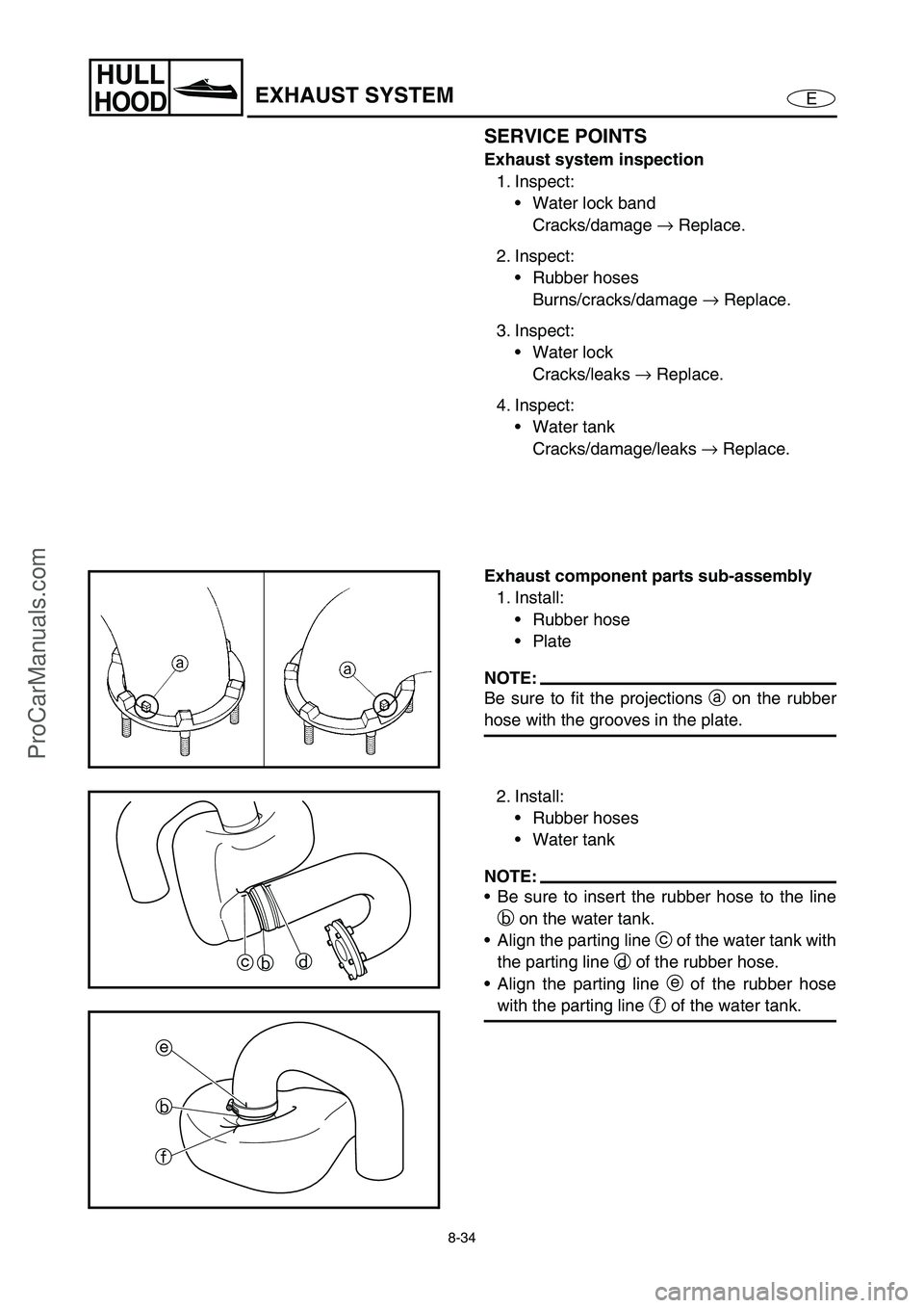
Exhaust component parts sub-assembly
1. Install:
Rubber hose
Plate
NOTE:
Be sure to fit the projections a
on the rubber
hose with the grooves in the plate.
2. Install:
Rubber hoses
Water tank
NOTE:
Be sure to insert the rubber hose to the line
b
on the water tank.
Align the parting line c
of the water tank with
the parting line d
of the rubber hose.
Align the parting line e
of the rubber hose
with the parting line f
of the water tank.
b cd
e
b
f
ProCarManuals.com
Page 329 of 347
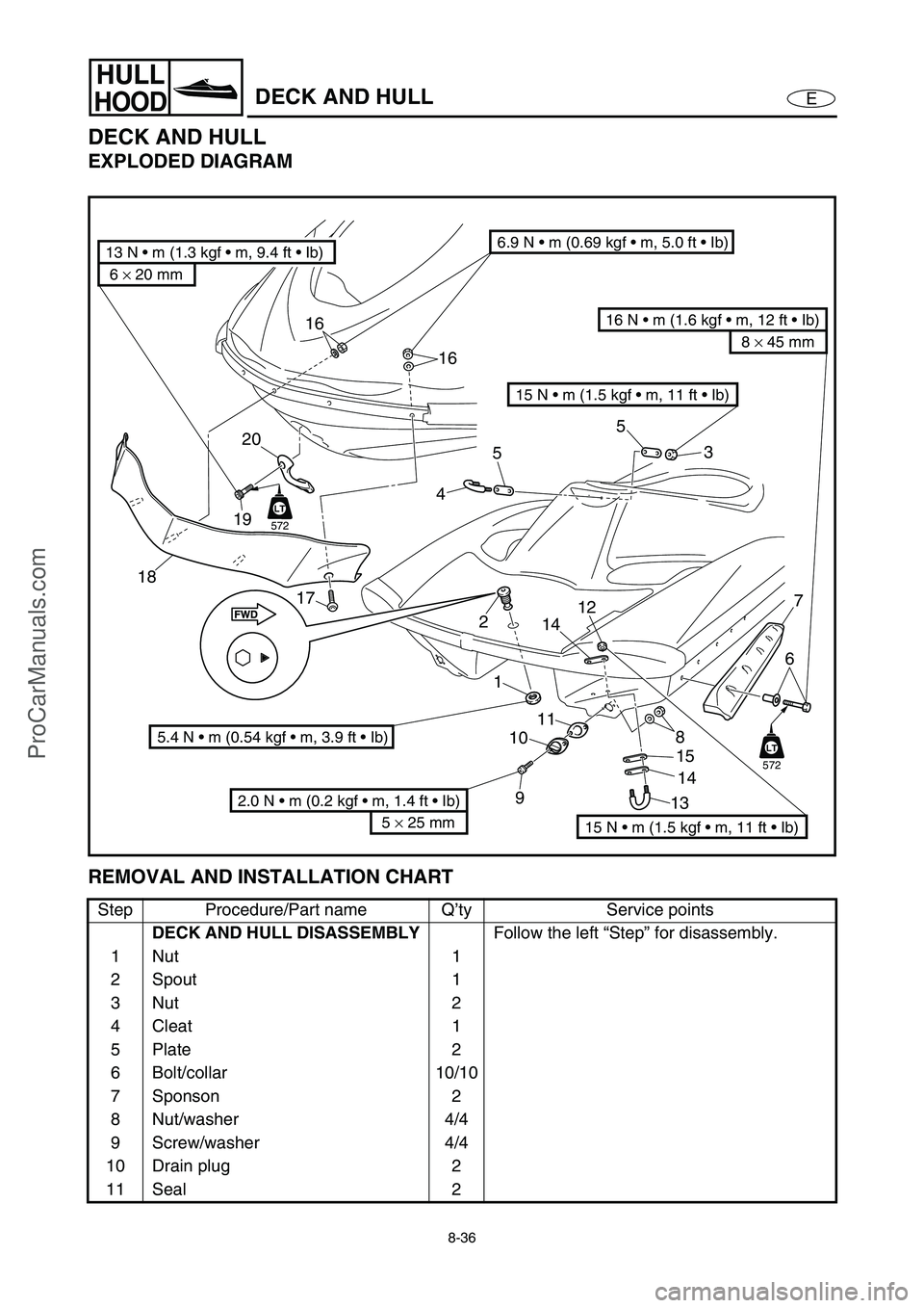
8-36
E
HULL
HOODDECK AND HULL
DECK AND HULL
EXPLODED DIAGRAM
REMOVAL AND INSTALLATION CHART
Step Procedure/Part name Q’ty Service points
DECK AND HULL DISASSEMBLY
Follow the left “Step” for disassembly.
1Nut 1
2 Spout 1
3Nut 2
4 Cleat 1
5Plate 2
6 Bolt/collar 10/10
7 Sponson 2
8 Nut/washer 4/4
9 Screw/washer 4/4
10 Drain plug 2
11 Seal 2
453
7
6
1 2
5
LT
572
16
16
19
17
18
9 10111315
1412
6 × 20 mm
13 N • m (1.3 kgf • m, 9.4 ft • Ib)6.9 N • m (0.69 kgf • m, 5.0 ft • Ib)
8 × 45 mm
16 N • m (1.6 kgf • m, 12 ft • Ib)
15 N • m (1.5 kgf • m, 11 ft • Ib)
5 × 25 mm
2.0 N • m (0.2 kgf • m, 1.4 ft • Ib) 5.4 N • m (0.54 kgf • m, 3.9 ft • Ib)
LT
572
LT
8
14
20
15 N • m (1.5 kgf • m, 11 ft • Ib)
ProCarManuals.com