ignition YAMAHA VX110 2005 Service Manual
[x] Cancel search | Manufacturer: YAMAHA, Model Year: 2005, Model line: VX110, Model: YAMAHA VX110 2005Pages: 347, PDF Size: 14.17 MB
Page 15 of 347

1-6
E
GEN
INFO
SPECIAL SERVICE TOOLS
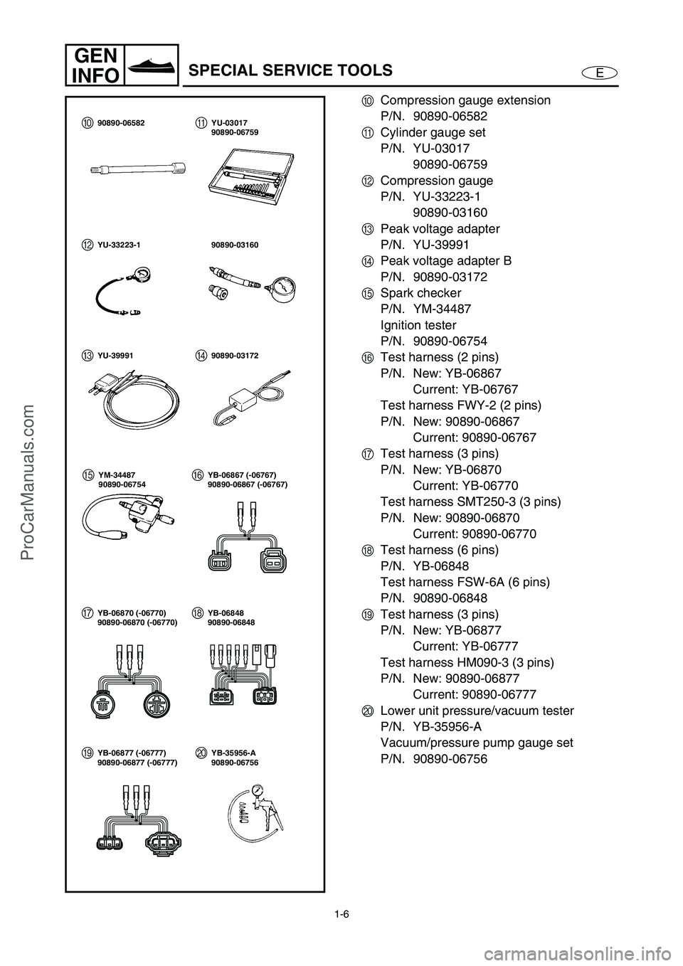
0
Compression gauge extension
P/N. 90890-06582
A
Cylinder gauge set
P/N. YU-03017
90890-06759
B
Compression gauge
P/N. YU-33223-1
90890-03160
C
Peak voltage adapter
P/N. YU-39991
D
Peak voltage adapter B
P/N. 90890-03172
E
Spark checker
P/N. YM-34487
Ignition tester
P/N. 90890-06754
F
Test harness (2 pins)
P/N. New: YB-06867
Current: YB-06767
Test harness FWY-2 (2 pins)
P/N. New: 90890-06867
Current: 90890-06767
G
Test harness (3 pins)
P/N. New: YB-06870
Current: YB-06770
Test harness SMT250-3 (3 pins)
P/N. New: 90890-06870
Current: 90890-06770
H
Test harness (6 pins)
P/N. YB-06848
Test harness FSW-6A (6 pins)
P/N. 90890-06848
I
Test harness (3 pins)
P/N. New: YB-06877
Current: YB-06777
Test harness HM090-3 (3 pins)
P/N. New: 90890-06877
Current: 90890-06777
J
Lower unit pressure/vacuum tester
P/N. YB-35956-A
Vacuum/pressure pump gauge set
P/N. 90890-06756
0A
B
C
EF
GH90890-06582 YU-03017
90890-06759
YU-33223-1 90890-03160
YU-39991 90890-03172
YM-34487
90890-06754YB-06867 (-06767)
90890-06867 (-06767)
YB-06870 (-06770)
90890-06870 (-06770)YB-06848
90890-06848
D
IJYB-06877 (-06777)
90890-06877 (-06777)YB-35956-A
90890-06756
ProCarManuals.com
Page 22 of 347

2-1
ESPECGENERAL SPECIFICATIONS
GENERAL SPECIFICATIONS
Item UnitModel
VX110 Sport VX110 Deluxe
Model code
Hull F1K
Engine/jet 6D3
Dimensions
Length mm (in) 3,220 (126.8)
Width mm (in) 1,170 (46.1)
Height mm (in) 1,150 (45.3)
Dry weight kg (lb) 325 (716)
Maximum capacity Person/kg (lb) 3/240 (530)
Performance
Maximum output kW (PS) @ r/min 81.0 (110) @ 8,000
Maximum fuel consumption l/h (US gal/h,
lmp gal/h)28.0 (7.4, 6.2)
Cruising range h 2.1
Engine
Engine type 4-stroke, L4, DOHC
Displacement cm
3 (cu. in) 1,052 (64.2)
Bore ×
stroke mm (in) 76.0 ×
58.0 (2.99 ×
2.28)
Compression ratio 11.4:1
Exhaust system Wet exhaust
Lubrication system Dry sump
Cooling system Water cooled
Starting system Electric starter
Ignition system TCI
Ignition timing Degree BTDC 5–BTDC 35
Spark plug model
(manufacturer)CR9EB (NGK)
Spark plug gap mm (in) 0.7–0.8 (0.028–0.031)
Battery capacity V/Ah 12/19
Generator output A @ r/min 12–21 @ 6,000
Drive unit
Propulsion system Jet pump
Jet pump type Axial flow, single stage
Impeller rotation Counterclockwise (viewed from rear)
Transmission Constant mesh 1-speed
Jet thrust nozzle horizontal
angleDegree 24 + 24
Jet thrust nozzle trim angle Degree 3
Reverse system—Reverse gate
ProCarManuals.com
Page 28 of 347

2-7
ESPECMAINTENANCE SPECIFICATIONS
ELECTRICAL
Item UnitModel
VX110 Sport VX110 Deluxe
Battery
Type Fluid
Capacity V/Ah 12/19
Specific gravity 1.28
ECM unit
(B/R – R/Y, B/W – R/Y,
B/Y – R/Y, B/G – R/Y)
Output peak voltage lower limit
@cranking (loaded) V 90
@2,000 r/min (loaded) V 130
@3,500 r/min (loaded) V 140
Stator
Pickup coil (W/B – B/O)
Output peak voltage
@cranking (unloaded) V 8.0
@cranking (loaded) V 6.9
@2,000 r/min (loaded) V 19.4
@3,500 r/min (loaded) V 25.1
Lighting coil (G – G)
Output peak voltage
@cranking (unloaded) V 7.8
@2,000 r/min (unloaded) V 24.5
@3,500 r/min (unloaded) V 41.6
Pickup coil resistance
(W/B – B/O)Ω
(color) 459–561
Lighting coil resistance (G – G)Ω
(color) 0.23–0.29
Minimum charging current A @ r/min 14 @ 6,000
Ignition coil
Primary coil resistance
@20 °C (68 °F)Ω
1.19–1.61
Secondary coil resistance
@20 °C (68 °F) kΩ
8.5–11.5
Rectifier/regulator (R – B)
Output peak voltage
@3,500 r/min (unloaded) V 13.0
ProCarManuals.com
Page 33 of 347

2-12
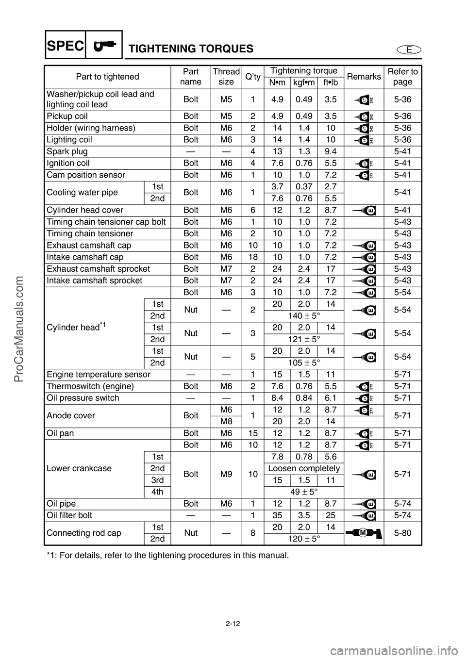
ESPECTIGHTENING TORQUES
Washer/pickup coil lead and
lighting coil leadBolt M5 1 4.9 0.49 3.5242LT5-36
Pickup coil Bolt M5 2 4.9 0.49 3.5
242LT5-36
Holder (wiring harness) Bolt M6 2 14 1.4 10
242LT5-36
Lighting coil Bolt M6 3 14 1.4 10
242LT5-36
Spark plug——4131.39.4 5-41
Ignition coil Bolt M6 4 7.6 0.76 5.5
572LT5-41
Cam position sensor Bolt M6 1 10 1.0 7.2
572LT5-41
Cooling water pipe1st
Bolt M6 13.70.372.7
5-41
2nd 7.6 0.76 5.5
Cylinder head cover Bolt M6 6 12 1.2 8.7
E5-41
Timing chain tensioner cap bolt Bolt M6 1 10 1.0 7.2 5-43
Timing chain tensioner Bolt M6 2 10 1.0 7.2 5-43
Exhaust camshaft cap Bolt M6 10 10 1.0 7.2
E5-43
Intake camshaft cap Bolt M6 18 10 1.0 7.2
E5-43
Exhaust camshaft sprocket Bolt M7 2 24 2.4 17
E5-43
Intake camshaft sprocket Bolt M7 2 24 2.4 17
E5-43
Cylinder head
*1 Bolt M6 3 10 1.0 7.2
E5-54
1st
Nut—220 2.0 14
E5-54
2nd 140 ±
5°
1st
Nut—320 2.0 14
E5-54
2nd 121 ±
5°
1st
Nut—520 2.0 14
E5-54
2nd 105 ±
5°
Engine temperature sensor——1 15 1.5 11 5-71
Thermoswitch (engine) Bolt M6 2 7.6 0.76 5.5
572LT5-71
Oil pressure switch——1 8.4 0.84 6.1
572LT5-71
Anode cover BoltM6
112 1.2 8.7
271LT5-71
M8 20 2.0 14
Oil pan Bolt M6 15 12 1.2 8.7
572LT5-71
Lower crankcaseBolt M6 10 12 1.2 8.7
572LT5-71
1st
Bolt M9 107.80.785.6
E5-71 2nd Loosen completely
3rd 15 1.5 11
4th 49 ±
5°
Oil pipe Bolt M6 1 12 1.2 8.7
E5-74
Oil filter bolt——1353.525
E5-74
Connecting rod cap1st
Nut—820 2.0 14
M5-80
2nd 120 ±
5°
*1: For details, refer to the tightening procedures in this manual.Part to tightenedPart
nameThread
sizeQ’tyTightening torque
RemarksRefer to
page
Nmkgfmftlb
ProCarManuals.com
Page 44 of 347

2-23
ESPECCABLE AND HOSE ROUTING
13
90A
C B
88
4567
2
E
D
F
È
É
Í
Ê
Ë
Ì A-A
AA
Î
1Oil separator breather hose (to air intake duct)
2Wiring harness
3Ignition coil lead #1
4Ignition coil lead #2
5Ignition coil lead #3
6Ignition coil lead #4
7Cam position sensor
8Ignition coil
9ECM
0Rectifier/regulator
AOil pressure switch couplerBThermoswitch (exhaust) coupler
CGround lead plate
DWiring harness
EThermoswitch (exhaust) lead
FOil pressure switch lead
ÈFasten the oil separator breather hose (to air
intake duct) at the paint mark with a holder.
É15–25 mm (0.59–0.98 in)
ÊTo fuse box
ËTo multifunction meter
ProCarManuals.com
Page 46 of 347

2-25
ESPECCABLE AND HOSE ROUTING
D-D
A-A
B-B
0
8
5
C-C
9
5 Ú
Ù
É
È
Ð
DD
5
6
A
A
1
2
7
34
Î
Ó ÒÌÑÑÌÑ
Ì
Ì
Ë Ë
Ê
Ø×Ö Ô
Õ
Í
Ï
C
CB
B
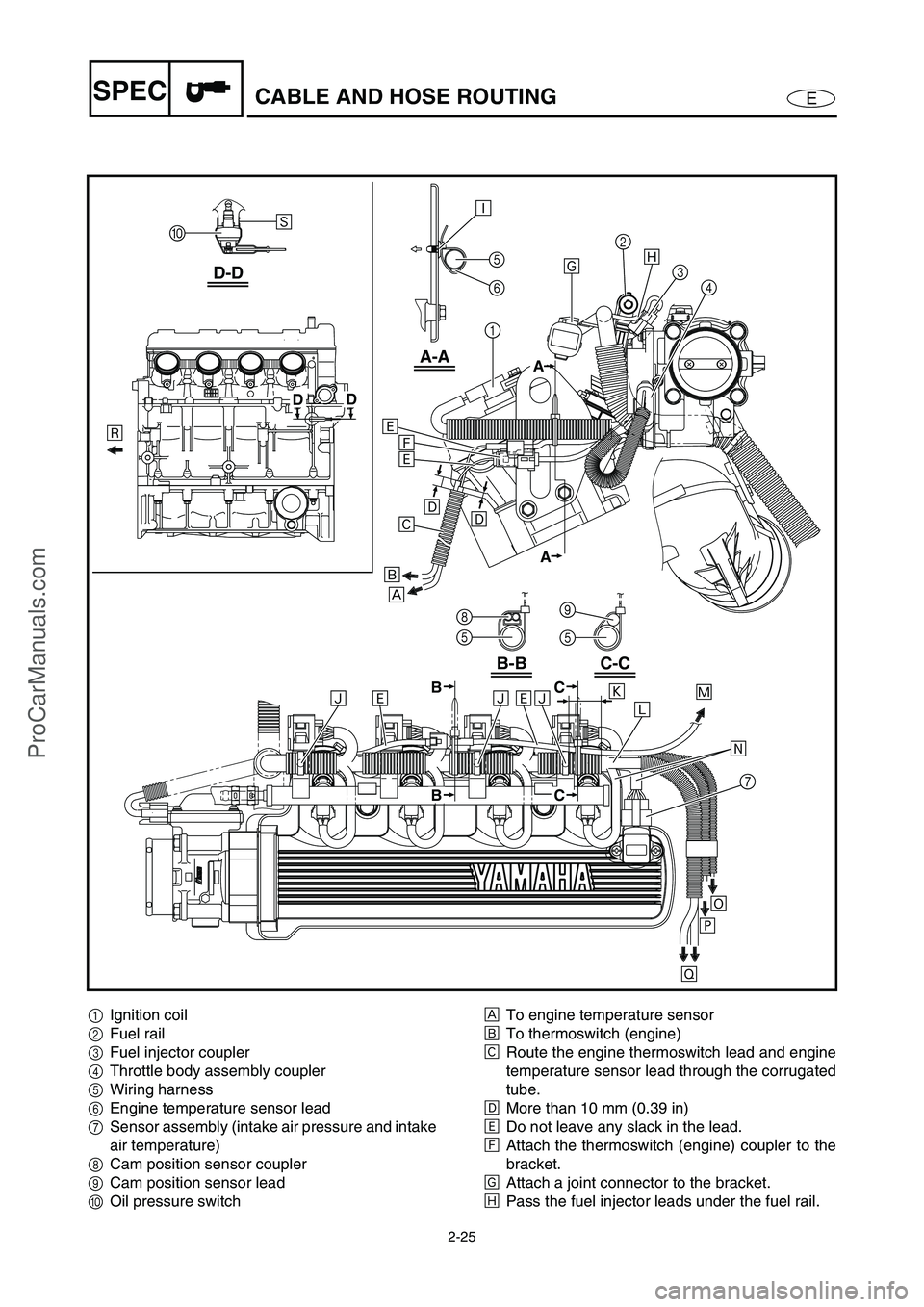
1Ignition coil
2Fuel rail
3Fuel injector coupler
4Throttle body assembly coupler
5Wiring harness
6Engine temperature sensor lead
7Sensor assembly (intake air pressure and intake
air temperature)
8Cam position sensor coupler
9Cam position sensor lead
0Oil pressure switchÈTo engine temperature sensor
ÉTo thermoswitch (engine)
ÊRoute the engine thermoswitch lead and engine
temperature sensor lead through the corrugated
tube.
ËMore than 10 mm (0.39 in)
ÌDo not leave any slack in the lead.
ÍAttach the thermoswitch (engine) coupler to the
bracket.
ÎAttach a joint connector to the bracket.
ÏPass the fuel injector leads under the fuel rail.
ProCarManuals.com
Page 57 of 347

3-8
E
INSP
ADJ
FUEL SYSTEM/POWER UNIT
Water separator inspection
1. Inspect:
Water separator 1
Water accumulation →
Drain.
NOTE:
To drain the water, remove the drain plug.
POWER UNIT
Valve clearance adjustment
The following procedure applies to all of the
valves.
NOTE:
Valve clearance adjustment should be made
on a cold engine, at room temperature.
When the valve clearance is to be measured
or adjusted, the piston must be at top dead
center (TDC) of the compression stroke.
1. Remove:
Ignition coils
Spark plugs
Cylinder head cover
Cylinder head cover gasket
Refer to “CAMSHAFTS” in Chapter 5.
2. Install:
Dial gauge needle
Dial gauge stand 1
(into spark plug hole #1)
Dial gauge 2
Dial gauge stand:
90890-06583
Dial gauge needle:
90890-06584
Dial gauge stand set:
YB-06585/90890-06585
Dial indicator gauge:
YU-03097
Dial gauge set:
90890-012522
1
ProCarManuals.com
Page 69 of 347

3-20
E
INSP
ADJ
POWER UNIT
Spark plug inspection
1. Remove:
Ignition coils
CAUTION:
Be careful not to get any foreign sub-
stances or water in spark plug hole.
2. Inspect:
Electrodes 1
Damage/wear →
Replace.
Insulator color 2
Distinctly different color →
Check the
engine condition.
Color guide:
Medium to light tan color:
Normal
Whitish color:
Lean fuel mixture
Air leak
Incorrect settings
Blackish color:
Overly rich mixture
Electrical malfunction
Defective spark plug
3. Clean:
Spark plug
(with a spark plug cleaner or wire brush)
4. Measure:
Spark plug gap a
Out of specification →
Regap.
Spark plug gap:
0.7–0.8 mm (0.028–0.031 in)
ProCarManuals.com
Page 70 of 347

3-21
E
INSP
ADJ
POWER UNIT
5. Tighten:
Spark plug
NOTE:
Before installing the spark plug, clean the
gasket surface and spark plug surface. Also,
it is suggested to apply a thin film of anti-
seize compound to the spark plug threads to
prevent thread seizure.
If a torque wrench is not available, a good
estimate of the correct tightening torque for a
new spark plug is to finger tighten a
the
spark plug and then tighten it another 1/4 to
1/2 of a turnb
.
T R..
Spark plug:
13 N m (1.3 kgf m, 9.4 ft lb)
6. Install:
Ignition coils
T R..
Ignition coil bolt:
7.6 N m (0.76 kgf m, 5.5 ft lb)
LOCTITE 572
ProCarManuals.com
Page 103 of 347

5-4
EPOWRENGINE UNIT
SERVICE POINTS
Compression pressure measurement
The following procedure applies to all of the
cylinders.
NOTE:
Insufficient compression pressure will result in
a loss of performance.
1. Measure:
Valve clearance
Out of specification →
Adjust.
Refer to “POWER UNIT” in Chapter 3.
2. Warm the engine up, and then put the
watercraft in a horizontal position.
3. Remove:
Ignition coils
Spark plugs
CAUTION:
Before removing the spark plugs, use com-
pressed air to blow away any dirt accumu-
lated in the spark plug wells to prevent it
from falling into the cylinders.
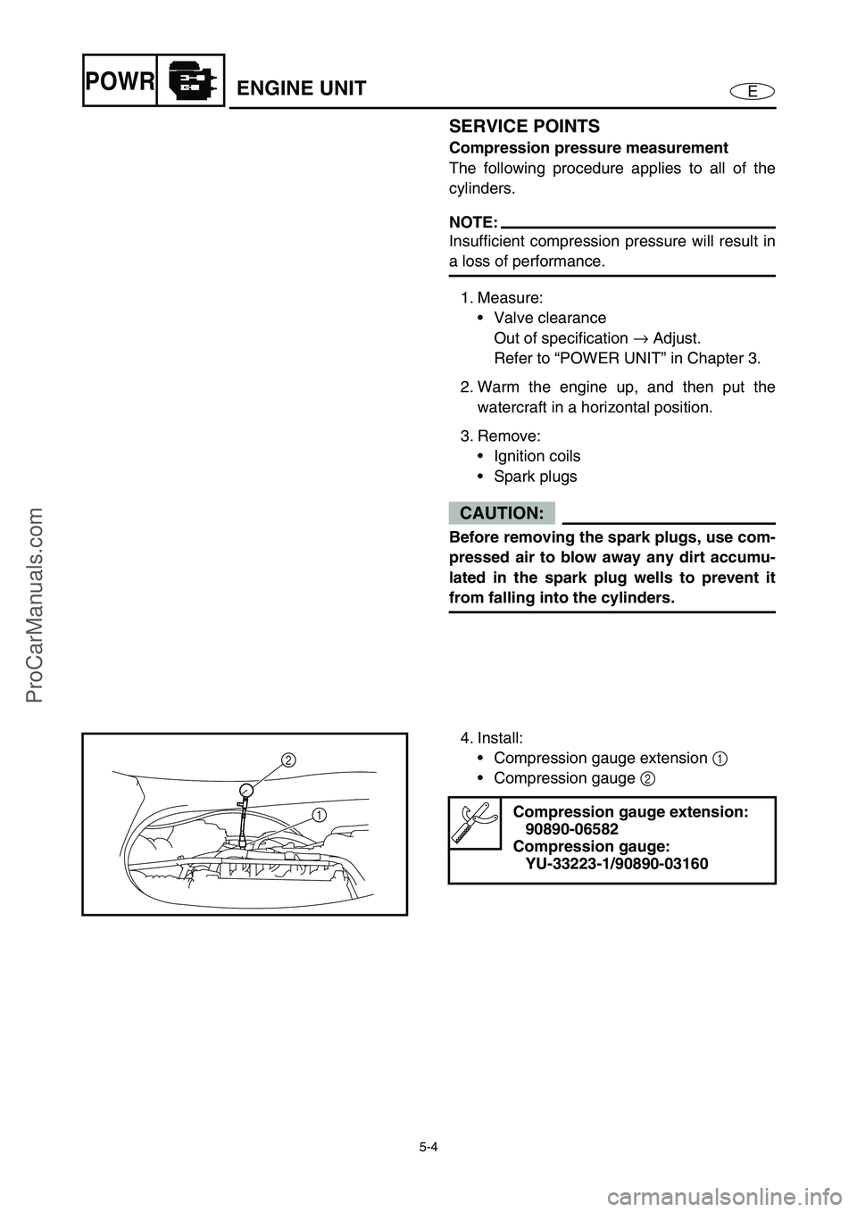
4. Install:
Compression gauge extension 1
Compression gauge 2
Compression gauge extension:
90890-06582
Compression gauge:
YU-33223-1/90890-03160
2
1
ProCarManuals.com