light YAMAHA VX110 2005 Service Manual
[x] Cancel search | Manufacturer: YAMAHA, Model Year: 2005, Model line: VX110, Model: YAMAHA VX110 2005Pages: 347, PDF Size: 14.17 MB
Page 28 of 347

2-7
ESPECMAINTENANCE SPECIFICATIONS
ELECTRICAL
Item UnitModel
VX110 Sport VX110 Deluxe
Battery
Type Fluid
Capacity V/Ah 12/19
Specific gravity 1.28
ECM unit
(B/R – R/Y, B/W – R/Y,
B/Y – R/Y, B/G – R/Y)
Output peak voltage lower limit
@cranking (loaded) V 90
@2,000 r/min (loaded) V 130
@3,500 r/min (loaded) V 140
Stator
Pickup coil (W/B – B/O)
Output peak voltage
@cranking (unloaded) V 8.0
@cranking (loaded) V 6.9
@2,000 r/min (loaded) V 19.4
@3,500 r/min (loaded) V 25.1
Lighting coil (G – G)
Output peak voltage
@cranking (unloaded) V 7.8
@2,000 r/min (unloaded) V 24.5
@3,500 r/min (unloaded) V 41.6
Pickup coil resistance
(W/B – B/O)Ω
(color) 459–561
Lighting coil resistance (G – G)Ω
(color) 0.23–0.29
Minimum charging current A @ r/min 14 @ 6,000
Ignition coil
Primary coil resistance
@20 °C (68 °F)Ω
1.19–1.61
Secondary coil resistance
@20 °C (68 °F) kΩ
8.5–11.5
Rectifier/regulator (R – B)
Output peak voltage
@3,500 r/min (unloaded) V 13.0
ProCarManuals.com
Page 33 of 347

2-12
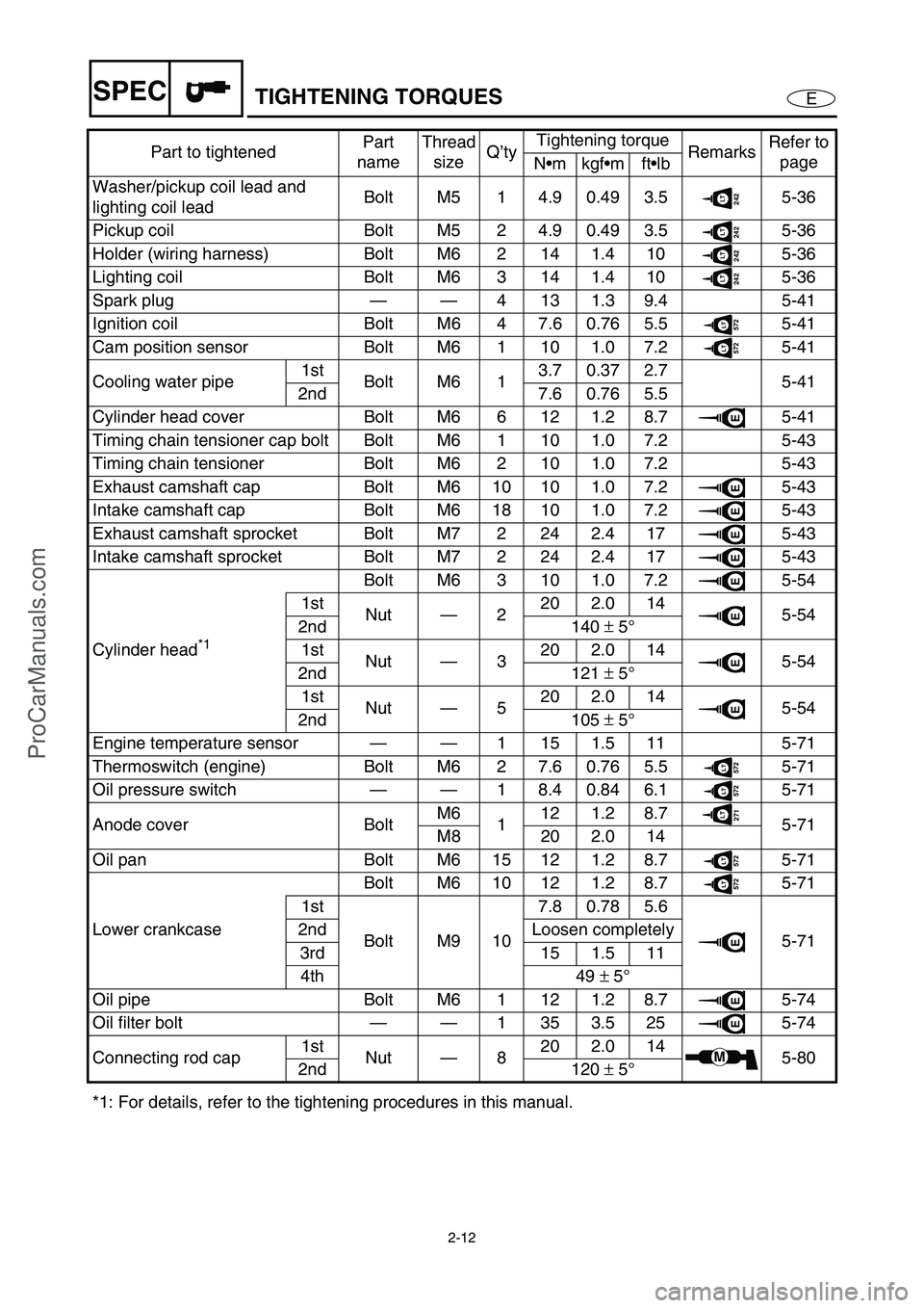
ESPECTIGHTENING TORQUES
Washer/pickup coil lead and
lighting coil leadBolt M5 1 4.9 0.49 3.5242LT5-36
Pickup coil Bolt M5 2 4.9 0.49 3.5
242LT5-36
Holder (wiring harness) Bolt M6 2 14 1.4 10
242LT5-36
Lighting coil Bolt M6 3 14 1.4 10
242LT5-36
Spark plug——4131.39.4 5-41
Ignition coil Bolt M6 4 7.6 0.76 5.5
572LT5-41
Cam position sensor Bolt M6 1 10 1.0 7.2
572LT5-41
Cooling water pipe1st
Bolt M6 13.70.372.7
5-41
2nd 7.6 0.76 5.5
Cylinder head cover Bolt M6 6 12 1.2 8.7
E5-41
Timing chain tensioner cap bolt Bolt M6 1 10 1.0 7.2 5-43
Timing chain tensioner Bolt M6 2 10 1.0 7.2 5-43
Exhaust camshaft cap Bolt M6 10 10 1.0 7.2
E5-43
Intake camshaft cap Bolt M6 18 10 1.0 7.2
E5-43
Exhaust camshaft sprocket Bolt M7 2 24 2.4 17
E5-43
Intake camshaft sprocket Bolt M7 2 24 2.4 17
E5-43
Cylinder head
*1 Bolt M6 3 10 1.0 7.2
E5-54
1st
Nut—220 2.0 14
E5-54
2nd 140 ±
5°
1st
Nut—320 2.0 14
E5-54
2nd 121 ±
5°
1st
Nut—520 2.0 14
E5-54
2nd 105 ±
5°
Engine temperature sensor——1 15 1.5 11 5-71
Thermoswitch (engine) Bolt M6 2 7.6 0.76 5.5
572LT5-71
Oil pressure switch——1 8.4 0.84 6.1
572LT5-71
Anode cover BoltM6
112 1.2 8.7
271LT5-71
M8 20 2.0 14
Oil pan Bolt M6 15 12 1.2 8.7
572LT5-71
Lower crankcaseBolt M6 10 12 1.2 8.7
572LT5-71
1st
Bolt M9 107.80.785.6
E5-71 2nd Loosen completely
3rd 15 1.5 11
4th 49 ±
5°
Oil pipe Bolt M6 1 12 1.2 8.7
E5-74
Oil filter bolt——1353.525
E5-74
Connecting rod cap1st
Nut—820 2.0 14
M5-80
2nd 120 ±
5°
*1: For details, refer to the tightening procedures in this manual.Part to tightenedPart
nameThread
sizeQ’tyTightening torque
RemarksRefer to
page
Nmkgfmftlb
ProCarManuals.com
Page 69 of 347

3-20
E
INSP
ADJ
POWER UNIT
Spark plug inspection
1. Remove:
Ignition coils
CAUTION:
Be careful not to get any foreign sub-
stances or water in spark plug hole.
2. Inspect:
Electrodes 1
Damage/wear →
Replace.
Insulator color 2
Distinctly different color →
Check the
engine condition.
Color guide:
Medium to light tan color:
Normal
Whitish color:
Lean fuel mixture
Air leak
Incorrect settings
Blackish color:
Overly rich mixture
Electrical malfunction
Defective spark plug
3. Clean:
Spark plug
(with a spark plug cleaner or wire brush)
4. Measure:
Spark plug gap a
Out of specification →
Regap.
Spark plug gap:
0.7–0.8 mm (0.028–0.031 in)
ProCarManuals.com
Page 132 of 347

5-33
EPOWRGENERATOR AND STARTER MOTOR
GENERATOR AND STARTER MOTOR
EXPLODED DIAGRAM
REMOVAL AND INSTALLATION CHART
Step Procedure/Part name Q’ty Service points
GENERATOR COVER AND
FLYWHEEL MAGNETO
REMOVALFollow the left “Step” for removal.
Engine unit Refer to “ENGINE UNIT”.
1 Nut/washer 1/1
2 Starter motor lead 1
3Bolt 2
4 Battery negative lead 1
5 Starter motor 1
6 Band 1
7 Lighting coil coupler 1
4 3
2 1
5
7
89
1113 12
18 16171920 21
15 14
AA
E
E
E
LT
572
LT
572
AA
AA
8 × 30 mm
18 N m (1.8 kgf
m, 13 ft
Ib)
4.9 N
m (0.49 kgf m, 3.5 ft Ib)
10 × 47 mm
75 N m (7.5 kgf
m, 54 ft
Ib) 8 × 20 mm
24 N m (2.4 kgf
m, 17 ft
Ib)
10 × 60 mm
2nd 50 N m (5.0 kgf
m, 36 ft
Ib) 1st 15 N m (1.5 kgf
m, 11 ft
Ib)
6
2nd 50 N m (5.0 kgf
m, 36 ft
Ib) 1st 15 N m (1.5 kgf m, 11 ft Ib)
10 × 135 mm
10
LT
572
LT
572
ProCarManuals.com
Page 136 of 347

5-37
EPOWRGENERATOR AND STARTER MOTOR
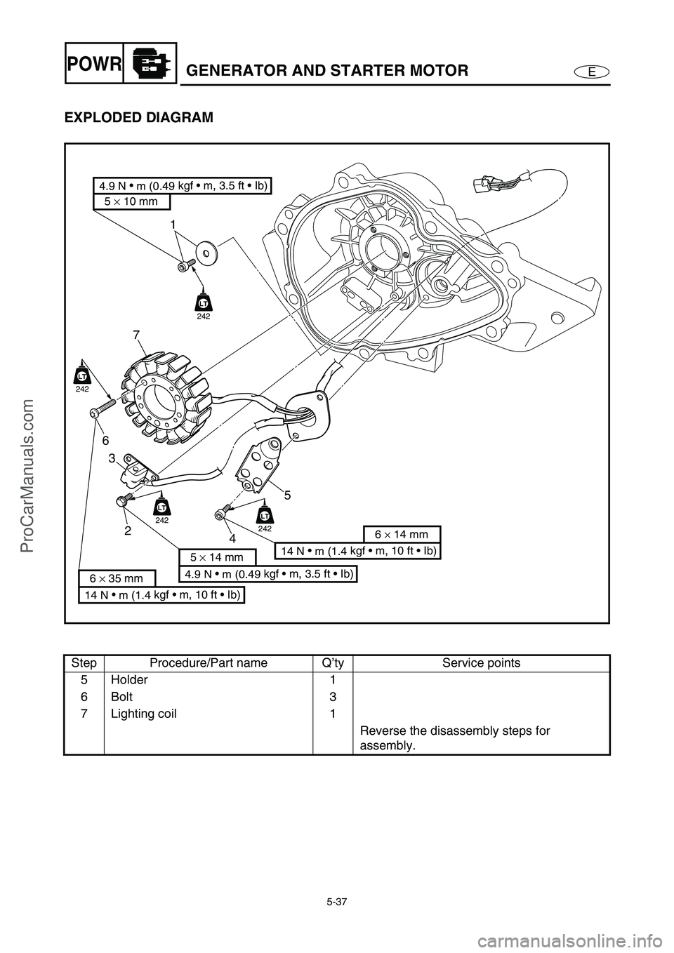
EXPLODED DIAGRAM
Step Procedure/Part name Q’ty Service points
5 Holder 1
6Bolt 3
7 Lighting coil 1
Reverse the disassembly steps for
assembly.
1
7
6
3
2
45
LT
242
LT
242
LT
242LT
242
14 N
m (1.4 kgf m, 10 ft Ib)
6 × 14 mm
4.9 N
m (0.49 kgf m, 3.5 ft Ib)
5 × 14 mm
14 N
m (1.4 kgf m, 10 ft Ib)
6 × 35 mm
4.9 N
m (0.49 kgf m, 3.5 ft Ib)
5 × 10 mm
ProCarManuals.com
Page 148 of 347

5-49
EPOWRCAMSHAFTS
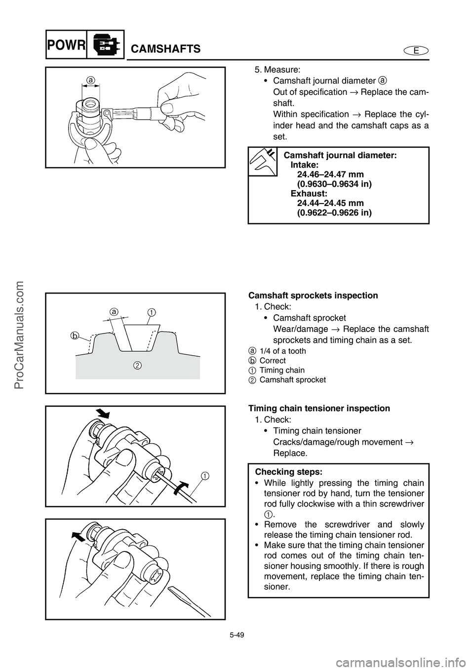
5. Measure:
Camshaft journal diameter a
Out of specification →
Replace the cam-
shaft.
Within specification →
Replace the cyl-
inder head and the camshaft caps as a
set.
Camshaft journal diameter:
Intake:
24.46–24.47 mm
(0.9630–0.9634 in)
Exhaust:
24.44–24.45 mm
(0.9622–0.9626 in)
Camshaft sprockets inspection
1. Check:
Camshaft sprocket
Wear/damage →
Replace the camshaft
sprockets and timing chain as a set.
a
1/4 of a tooth
b
Correct
1Timing chain
2Camshaft sprocket
Timing chain tensioner inspection
1. Check:
Timing chain tensioner
Cracks/damage/rough movement →
Replace.
Checking steps:
While lightly pressing the timing chain
tensioner rod by hand, turn the tensioner
rod fully clockwise with a thin screwdriver
1
.
Remove the screwdriver and slowly
release the timing chain tensioner rod.
Make sure that the timing chain tensioner
rod comes out of the timing chain ten-
sioner housing smoothly. If there is rough
movement, replace the timing chain ten-
sioner.
ProCarManuals.com
Page 150 of 347

5-51
EPOWRCAMSHAFTS
Install the exhaust and intake camshaft
caps.
NOTE:
Gradually tighten the intake and exhaust
camshaft cap bolts in 2–3 steps in the
sequence shown.
T R..
Camshaft cap bolt:
10 N m (1.0 kgf m, 7.2 ft lb)
NOTE:
Make sure that the punch marks c
on the
camshafts are aligned with the arrow marks
d
on the camshaft caps.
Out of alignment →
Reinstall.
Remove the wire from the timing chain.
10 1 4 5 8
17 5 1 4 8 15 9 12 149 3 2
7 6
18 7 3 2 6
13 11 10 16
3. Install:
Timing chain tensioner
Installation steps:
While lightly pressing the timing chain
tensioner rod by hand, turn the tensioner
rod fully clockwise with a thin screwdriver
1
.
NOTE:
Make sure that the tensioner rod has been
fully set clockwise.
With the timing chain tensioner rod
turned all the way into the timing chain
tensioner housing (with the thin screw-
driver still installed), install the gasket and
the timing chain tensioner 2
onto the cyl-
inder block.
WARNING
Always use a new gasket.
Tighten the timing chain tensioner bolts
3
to the specified torque.
NOTE:
The “UP” mark on the timing chain ten-
sioner should face up.
33
2
ProCarManuals.com
Page 169 of 347

5-70
EPOWRVALVES AND VALVE SPRINGS
2. Compress the valve spring, and then
install the valve cotter 1
using a thin
screwdriver with a small amount of grease
applied to it.
Valve spring compressor:
YM-01253/90890-04019
Valve spring compressor
attachment:
(for the intake valve):
YM-04114/90890-04114
(for the exhaust valve):
YM-04108/90890-04108
3. Lightly tap the valve spring retainer with a
plastic hammer to set the valve cotter
securely.
NOTE:
Apply engine oil to the valve pads and valve
lifters before installation.
ProCarManuals.com
Page 226 of 347

E
–+ELEC
FUEL CONTROL SYSTEM ........................................................................... 7-31
WIRING DIAGRAM ................................................................................. 7-31
ELECTRIC FUEL PUMP ......................................................................... 7-33
FUEL SENDER ....................................................................................... 7-33
FUEL INJECTOR .................................................................................... 7-34
MAIN AND FUEL PUMP RELAY............................................................. 7-34
OIL PRESSURE SWITCH ....................................................................... 7-34
THERMOSWITCH (ENGINE).................................................................. 7-34
THERMOSWITCH (EXHAUST) .............................................................. 7-34
SLANT DETECTION SWITCH ................................................................ 7-34
REMOTE CONTROL UNIT (DELUXE MODEL ONLY) ........................... 7-34
THROTTLE POSITION SENSOR ........................................................... 7-34
ACCELERATOR POSITION SENSOR ................................................... 7-34
STARTING SYSTEM ..................................................................................... 7-35
WIRING DIAGRAM ................................................................................. 7-35
BATTERY ................................................................................................ 7-37
WIRING CONNECTIONS........................................................................ 7-37
FUSES..................................................................................................... 7-37
START SWITCH...................................................................................... 7-37
STARTER RELAY ................................................................................... 7-38
REMOTE CONTROL UNIT (DELUXE MODEL ONLY) ........................... 7-38
THROTTLE POSITION SENSOR ........................................................... 7-38
ACCELERATOR POSITION SENSOR ................................................... 7-38
STARTER MOTOR ........................................................................................ 7-39
EXPLODED DIAGRAM ........................................................................... 7-39
REMOVAL AND INSTALLATION CHART ............................................. 7-39
SERVICE POINTS .................................................................................. 7-41
Armature inspection .......................................................................... 7-41
Brush holder inspection..................................................................... 7-42
Starter motor front cover inspection .................................................. 7-42
CHARGING SYSTEM .................................................................................... 7-43
WIRING DIAGRAM ................................................................................. 7-43
FUSE ....................................................................................................... 7-44
BATTERY ................................................................................................ 7-44
LIGHTING COIL ...................................................................................... 7-44
RECTIFIER/REGULATOR ...................................................................... 7-44
OFF THROTTLE STEERING SYSTEM......................................................... 7-45
WIRING DIAGRAM ................................................................................. 7-45
STEERING SENSOR .............................................................................. 7-47
ECM......................................................................................................... 7-47
PICKUP COIL .......................................................................................... 7-47
THROTTLE POSITION SENSOR ........................................................... 7-47
ACCELERATOR POSITION SENSOR ................................................... 7-47
ProCarManuals.com
Page 228 of 347

7-1
E
–+ELECELECTRICAL COMPONENTS
ELECTRICAL COMPONENTS
O
N
M
L
K
J
I
H
G
F
E
D
C
B
A
0
91
2
3
4
5
6
7
8
1Thermoswitch (engine)
2Fuse box
3Slant detection switch
4Starter motor
5Engine temperature sensor
6Spark plugs and ignition coils
7Cam position sensor
8Battery
9Speed sensor
0Sensor assembly (intake air
pressure and intake air tem-
perature)AOil pressure switch
BFuel injectors
CThermoswitch (exhaust)
DRectifier/regulator
EECM
FThrottle body assembly
GLighting coil and pickup coil
HEngine stop switch, engine
shut-off switch, and start
switch
ISteering sensor
JBuzzerKAccelerator position sensor
LElectric fuel pump
MFuel sender
NMultifunction meter
ORemote control unit (Deluxe
model only)
ProCarManuals.com