YAMAHA WR 250F 2006 Manuale de Empleo (in Spanish)
Manufacturer: YAMAHA, Model Year: 2006, Model line: WR 250F, Model: YAMAHA WR 250F 2006Pages: 900, tamaño PDF: 23.77 MB
Page 301 of 900
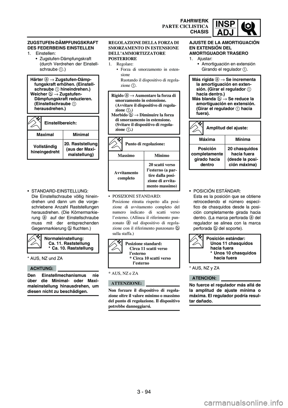
INSP
ADJ
3 - 94
ZUGSTUFEN-DÄMPFUNGSKRAFT
DES FEDERBEINS EINSTELLEN
1. Einstellen:
Zugstufen-Dämpfungskraft
(durch Verdrehen der Einstell-
schraube
1.)
Härter a → Zugstufen-Dämp-
fungskraft erhöhen. (Einstell-
schraube 1 hineindrehen.)
Weicher b → Zugstufen-
Dämpfungskraft reduzieren.
(Einstellschraube 1
herausdrehen.)
Einstellbereich:
Maximal Minimal
Vollständig
hineingedreht20. Raststellung
(aus der Maxi-
malstellung)
STANDARD-EINSTELLUNG:
Die Einstellschraube völlig hinein-
drehen und dann um die vorge-
schriebene Anzahl Raststellungen
herausdrehen. (Die Körnermarkie-
rung
a auf der Einstellschraube
muss mit der entsprechenden
Gegenmarkierung
b fluchten.)
* AUS, NZ und ZA
ACHTUNG:
Den Einstellmechanismus nie
über die Minimal- oder Maxi-
maleinstellung hinausdrehen, um
diesen nicht zu beschädigen.
Normaleinstellung:
Ca. 11. Raststellung
* Ca. 10. Raststellung
REGOLAZIONE DELLA FORZA DI
SMORZAMENTO IN ESTENSIONE
DELL’AMMORTIZZATORE
POSTERIORE
1. Regolare:
Forza di smorzamento in esten-
sione
Ruotando il dispositivo di regola-
zione 1.
POSIZIONE STANDARD:
Posizione ritratta rispetto alla posi-
zione di avvitamento completo del
numero indicato di scatti verso
l’esterno. (Allinea il riferimento pun-
zonato a sul dispositivo di regola-
zione con il riferimento punzonato b
sulla staffa.)
* AUS, NZ e ZA
ATTENZIONE:
Non forzare il dispositivo di regola-
zione oltre il valore minimo o massimo
del punto di regolazione. Il dispositivo
potrebbe danneggiarsi. Rigido a → Aumentare la forza di
smorzamento in estensione.
(Avvitare il dispositivo di regola-
zione 1.)
Morbido b → Diminuire la forza
di smorzamento in estensione.
(Svitare il dispositivo di regola-
zione 1.)
Punto di regolazione:
Massimo Minimo
Avvitamento
completo20 scatti verso
l’esterno (a par-
tire dalla posi-
zione di avvita-
mento massimo)
Posizione standard:
Circa 11 scatti verso
l’esterno
* Circa 10 scatti verso
l’esterno
AJUSTE DE LA AMORTIGUACIÓN
EN EXTENSIÓN DEL
AMORTIGUADOR TRASERO
1. Ajustar:
Amortiguación en extensión
Girando el regulador
1.
Más rígida a → Se incrementa
la amortiguación en exten-
sión. (Girar el regulador 1
hacia dentro.)
Más blanda b → Se reduce la
amortiguación en extensión.
(Girar el regulador 1 hacia
fuera).
Amplitud del ajuste:
Máxima Mínima
Posición
completamente
girado hacia
dentro20 chasquidos
hacia fuera
(desde la posi-
ción máxima)
POSICIÓN ESTÁNDAR:
Esta es la posición que se obtiene
retrocediendo el número especí-
fico de chasquidos desde la posi-
ción completamente girada hacia
dentro. (La marca perforada
a del
regulador se alinea con la marca
perforada
b del soporte).
* AUS, NZ y ZA
ATENCION:
No fuerce el regulador más allá de
la amplitud de ajuste mínima o
máxima. El regulador podría resul-
tar dañado.
Posición estándar:
Unos 11 chasquidos
hacia fuera
* Unos 10 chasquidos
hacia fuera
FAHRWERK
PARTE CICLISTICA
CHASIS
Page 302 of 900
3 - 95
INSP
ADJ
EC36c000REAR SHOCK ABSORBER LOW
COMPRESSION DAMPING FORCE
ADJUSTMENT
1. Adjust:
Low compression damping
force
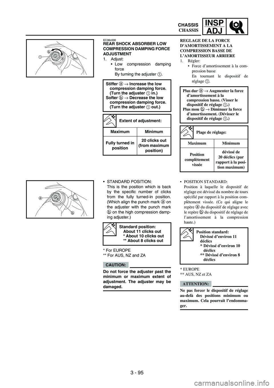
By turning the adjuster
1.
Stiffer a → Increase the low
compression damping force.
(Turn the adjuster 1 in.)
Softer b → Decrease the low
compression damping force.
(Turn the adjuster 1 out.)
Extent of adjustment:
Maximum Minimum
Fully turned in
position20 clicks out
(from maximum
position)
1b
a
STANDARD POSITION:
This is the position which is back
by the specific number of clicks
from the fully turned-in position.
(Which align the punch mark
a on
the adjuster with the punch mark
b on the high compression damp-
ing adjuster.)
* For EUROPE
** For AUS, NZ and ZA
CAUTION:
Do not force the adjuster past the
minimum or maximum extent of
adjustment. The adjuster may be
damaged.
Standard position:
About 11 clicks out
* About 10 clicks out
** About 8 clicks out
a
b
REGLAGE DE LA FORCE
D’AMORTISSEMENT A LA
COMPRESSION BASSE DE
L’AMORTISSEUR ARRIERE
1. Régler:
Force d’amortissement à la com-
pression basse
En tournant le dispositif de
réglage 1.
Plus dur a → Augmenter la force
d’amortissement à la
compression basse. (Visser le
dispositif de réglage 1.)
Plus mou b → Diminuer la force
d’amortissement. (Dévisser le
dispositif de réglage 1.)
Plage de réglage:
Maximum Minimum
Position
complètement
visséedévissé de
20 déclics (par
rapport à la posi-
tion maximum)
POSITION STANDARD:
Position à laquelle le dispositif de
réglage est dévissé du nombre de tours
spécifié par rapport à la position com-
plètement vissée. (Ce qui aligne le
repère a du dispositif de réglage avec
le repère b du dispositif de réglage de
l’amortissement à la compression
haute.)
* EUROPE
** AUS, NZ et ZA
ATTENTION:
Ne pas forcer le dispositif de réglage
au-delà des positions minimum ou
maximum. Cela pourrait l’endomma-
ger.
Position standard:
Dévissé d’environ 11
déclics
*Dévissé d’environ 10
déclics
** Dévissé d’environ 8
déclics
CHASSIS
CHASSIS
Page 303 of 900
INSP
ADJ
3 - 96
UNTERE DRUCKSTUFEN-
DÄMPFUNGSKRAFT DES
FEDERBEINS EINSTELLEN
1. Einstellen:
untere Druckstufen-Dämp-
fungskraft
(durch Verdrehen der Einstell-
schraube
1.)
Härter a → Untere Druckstu-
fen-Dämpfungskraft erhö-
hen. (Einstellschraube 1
hineindrehen.)
Weicher b → Untere Druckstu-
fen-Dämpfungskraft reduzie-
ren. (Einstellschraube 1
herausdrehen.)
Einstellbereich:
Maximal Minimal
Vollständig
hineingedreht20. Raststellung
(aus der Maxi-
malstellung)
STANDARD-EINSTELLUNG:
Die Einstellschraube völlig hinein-
drehen und dann um die vorge-
schriebene Anzahl Raststellungen
herausdrehen. (Die Körnermarkie-
rung
a auf der Einstellschraube
muss mit der entsprechenden
Gegenmarkierung
b fluchten.)
* EUROPE
** AUS, NZ und ZA
ACHTUNG:
Den Einstellmechanismus nie
über die Minimal- oder Maxi-
maleinstellung hinausdrehen, um
diesen nicht zu beschädigen.
Normaleinstellung:
Ca. 11. Raststellung
* Ca. 10. Raststellung
** Ca. 8. Raststellung
REGOLAZIONE DELLA FORZA DI
SMORZAMENTO IN BASSA COM-
PRESSIONE DELL’AMMORTIZ-
ZATORE POSTERIORE
1. Regolare:
Forza di smorzamento in bassa
compressione
Ruotando il dispositivo di regola-
zione 1.
POSIZIONE STANDARD:
Posizione ritratta rispetto alla posi-
zione di avvitamento completo del
numero indicato di scatti verso
l’esterno. (Allinea il riferimento pun-
zonato a sul dispositivo di regola-
zione con il riferimento punzonato b
sul dispositivo di regolazione di smor-
zamento in alta compressione.)
* EUROPE
** AUS, NZ e ZA
ATTENZIONE:
Non forzare il dispositivo di regola-
zione oltre il valore minimo o massimo
del punto di regolazione. Il dispositivo
potrebbe danneggiarsi. Rigido a → Aumentare la forza di
smorzamento in bassa
compressione. (Avvitare il
dispositivo di regolazione 1.)
Morbido b → Diminuire la forza
di smorzamento in bassa
compressione. (Svitare il
dispositivo di regolazione 1.)
Punto di regolazione:
Massimo Minimo
Avvitamento
completo20 scatti verso
l’esterno (a par-
tire dalla posi-
zione di avvita-
mento massimo)
Posizione standard:
Circa 11 scatti verso
l’esterno
* Circa 10 scatti verso
l’esterno
** Circa 8 scatti verso
l’esterno
AJUSTE DE LA AMORTIGUACIÓN
EN COMPRESIÓN BAJA DEL
AMORTIGUADOR TRASERO
1. Ajustar:
Amortiguación en compresión
baja
Girando el regulador
1.
Más rígida a → Se incrementa
la amortiguación en
compresión baja. (Girar el
regulador 1 hacia dentro.)
Más blanda b → Se reduce la
amortiguación en compre-
sión baja. (Girar el regulador
1 hacia fuera.)
Amplitud del ajuste:
Máxima Mínima
Posición
completamente
girado hacia
dentro20 chasquidos
hacia fuera
(desde la posi-
ción máxima)
POSICIÓN ESTÁNDAR:
Esta es la posición que se obtiene
retrocediendo el número especí-
fico de chasquidos desde la posi-
ción completamente girada hacia
dentro. (La marca perforada
a del
regulador se alinea con la marca
perforada
b del regulador de
amortiguación en compresión
alta).
* EUROPE
** AUS, NZ y ZA
ATENCION:
No fuerce el regulador más allá de
la amplitud de ajuste mínima o
máxima. El regulador podría resul-
tar dañado.
Posición estándar:
Unos 11 chasquidos
hacia fuera
* Unos 10 chasquidos
hacia fuera
** Unos 8 chasquidos
hacia fuera
FAHRWERK
PARTE CICLISTICA
CHASIS
Page 304 of 900
3 - 97
INSP
ADJ
EC36d000REAR SHOCK ABSORBER HIGH
COMPRESSION DAMPING FORCE
ADJUSTMENT
1. Adjust:
High compression damping
force
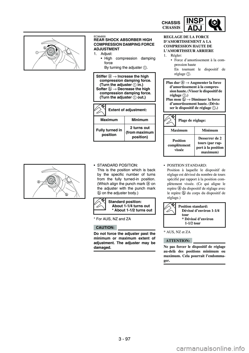
By turning the adjuster
1.
Stiffer a → Increase the high
compression damping force.
(Turn the adjuster 1 in.)
Softer b → Decrease the high
compression damping force.
(Turn the adjuster 1 out.)
Extent of adjustment:
Maximum Minimum
Fully turned in
position2 turns out
(from maximum
position)
1ba
STANDARD POSITION:
This is the position which is back
by the specific number of turns
from the fully turned-in position.
(Which align the punch mark
a on
the adjuster with the punch mark
b on the adjuster body.)
* For AUS, NZ and ZA
CAUTION:
Do not force the adjuster past the
minimum or maximum extent of
adjustment. The adjuster may be
damaged.
Standard position:
About 1-1/4 turns out
* About 1-1/2 turns out
a
b
REGLAGE DE LA FORCE
D’AMORTISSEMENT A LA
COMPRESSION HAUTE DE
L’AMORTISSEUR ARRIERE
1. Régler:
Force d’amortissement à la com-
pression haute
En tournant le dispositif de
réglage 1.
Plus dur a → Augmenter la force
d’amortissement à la compres-
sion haute. (Visser le dispositif de
réglage 1.)
Plus mou b → Diminuer la force
d’amortissement haute. (Dévis-
ser le dispositif de réglage 1.)
Plage de réglage:
Maximum Minimum
Position
complètement
visséeDesserrer de 2
tours (par rap-
port à la position
maximum)
POSITION STANDARD:
Position à laquelle le dispositif de
réglage est dévissé du nombre de tours
spécifié par rapport à la position com-
plètement vissée. (Ce qui aligne le
repère a du dispositif de réglage avec
le repère b du corps du dispositif de
réglage.)
* AUS, NZ et ZA
ATTENTION:
Ne pas forcer le dispositif de réglage
au-delà des positions minimum ou
maximum. Cela pourrait l’endomma-
ger.
Position standard:
Dévissé d’environ 1-1/4
tour
* Dévissé d’environ
1-1/2 tour
CHASSIS
CHASSIS
Page 305 of 900
INSP
ADJ
3 - 98
OBERE DRUCKSTUFEN-
DÄMPFUNGSKRAFT DES
FEDERBEINS EINSTELLEN
1. Einstellen:
obere Druckstufen-Dämp-
fungskraft
(durch Verdrehen der Einstell-
schraube
1.)
Härter a → Obere Druckstufen-
Dämpfungskraft erhöhen.
(Einstellschraube 1 hinein-
drehen.)
Weicher b → Obere Druckstu-
fen-Dämpfungskraft reduzie-
ren. (Einstellschraube 1
herausdrehen.)
Einstellbereich:
Maximal Minimal
Vollständig
hineingedreht2 Umdrehun-
gen heraus
(aus der Maxi-
malstellung)
STANDARD-EINSTELLUNG:
Die Einstellschraube völlig hinein-
drehen und dann um die vorge-
schriebene Anzahl Umdrehungen
herausdrehen. (Die Körnermarkie-
rung
a auf der Einstellschraube
muss mit der entsprechenden
Gegenmarkierung
b fluchten.)
* AUS, NZ und ZA
ACHTUNG:
Den Einstellmechanismus nie
über die Minimal- oder Maxi-
maleinstellung hinausdrehen, um
diesen nicht zu beschädigen.
Normaleinstellung:
Ca. 1 1/4
Umdrehungen heraus
* Ca. 1 1/2 Umdrehun-
gen heraus
REGOLAZIONE DELLA FORZA DI
SMORZAMENTO IN ALTA COM-
PRESSIONE DELL’AMMORTIZ-
ZATORE POSTERIORE
1. Regolare:
Forza di smorzamento in alta
compressione
Ruotando il dispositivo di regola-
zione 1.
POSIZIONE STANDARD:
Posizione ritratta rispetto alla posi-
zione di avvitamento completo del
numero indicato di rotazioni verso
l’esterno. (Allinea il riferimento pun-
zonato a sul dispositivo di regola-
zione con il riferimento punzonato b
sul corpo del dispositivo di regola-
zione)
* AUS, NZ e ZA
ATTENZIONE:
Non forzare il dispositivo di regola-
zione oltre il valore minimo o massimo
del punto di regolazione. Il dispositivo
potrebbe danneggiarsi. Rigido a → Aumentare la forza di
smorzamento in alta compres-
sione. (Avvitare il dispositivo di
regolazione 1.)
Morbido b → Diminuire la forza
di smorzamento in alta compres-
sione. (Svitare il dispositivo di
regolazione 1.)
Punto di regolazione:
Massimo Minimo
Avvitamento
completo2 rotazioni verso
l’esterno (a par-
tire dalla posi-
zione di avvita-
mento massimo)
Posizione standard:
Circa 1-1/4 rotazioni
verso l’esterno
* Circa 1-1/2 rotazioni
verso l’esterno
AJUSTE DE LA AMORTIGUACIÓN
EN COMPRESIÓN ALTA DEL
AMORTIGUADOR TRASERO
1. Ajustar:
Amortiguación en compresión
alta
Girando el regulador
1.
Más rígida a → Se incrementa
la amortiguación en compre-
sión alta. (Girar el regulador
1 hacia dentro.)
Más blanda b → Se reduce la
amortiguación en compre-
sión alta. (Girar el regulador
1 hacia fuera.)
Amplitud del ajuste:
Máxima Mínima
Posición
completamente
girado hacia
dentro2 vueltas hacia
fuera (desde la
posición
máxima)
POSICIÓN ESTÁNDAR:
Esta es la posición que se obtiene
retrocediendo el número especí-
fico de vueltas desde la posición
completamente girada hacia den-
tro. (La marca perforada
a del
regulador se alinea con la marca
perforada
b del cuerpo del regula-
dor).
* AUS, NZ y ZA
ATENCION:
No fuerce el regulador más allá de
la amplitud de ajuste mínima o
máxima. El regulador podría resul-
tar dañado.
Posición estándar:
Aproximadamente 1-1/4
de vuelta hacia fuera
* Aproximadamente
1-1/2 de vuelta hacia
fuera
FAHRWERK
PARTE CICLISTICA
CHASIS
Page 306 of 900
3 - 99
INSP
ADJ
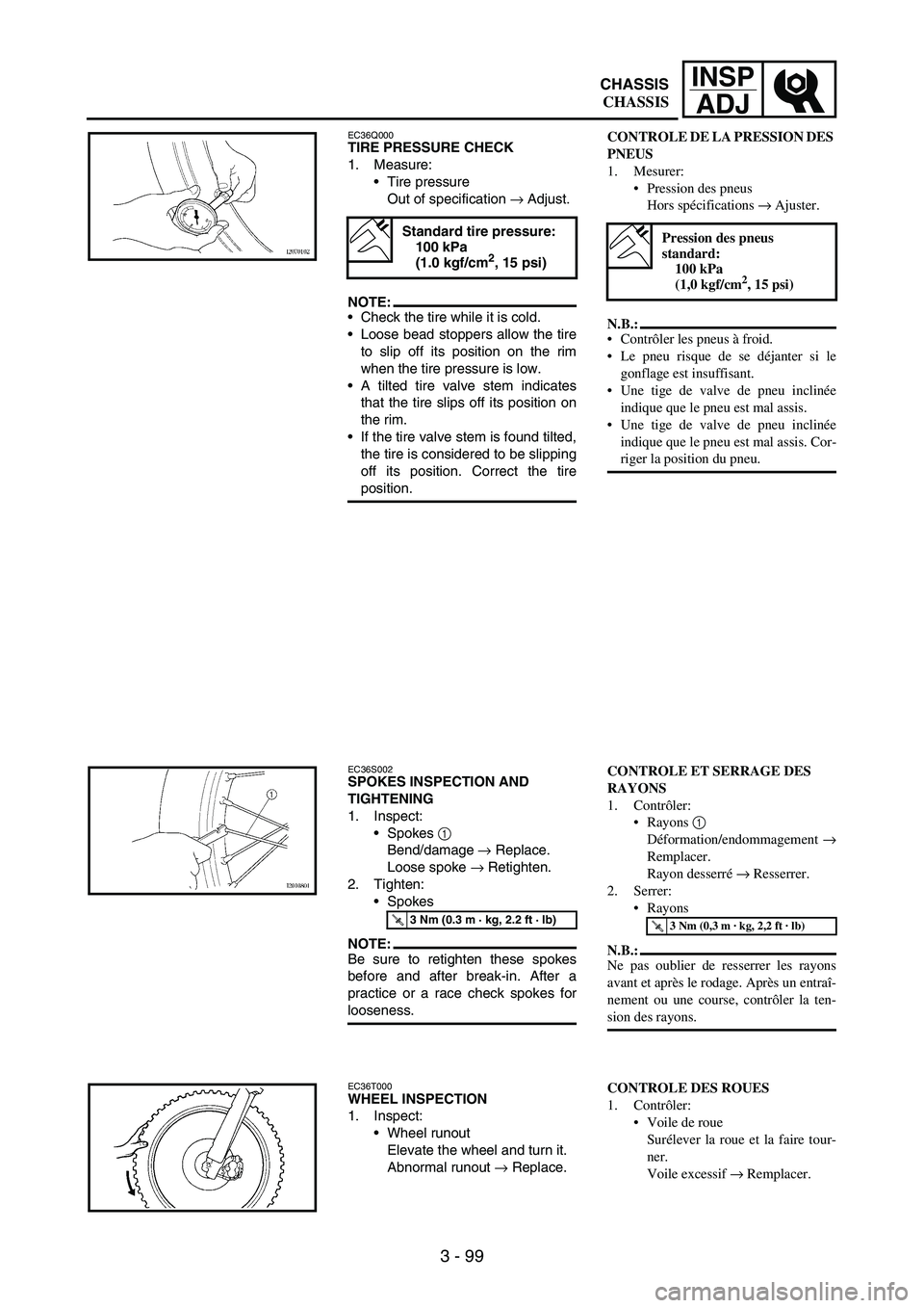
EC36Q000TIRE PRESSURE CHECK
1. Measure:
Tire pressure
Out of specification
→ Adjust.
NOTE:Check the tire while it is cold.
Loose bead stoppers allow the tire
to slip off its position on the rim
when the tire pressure is low.
A tilted tire valve stem indicates
that the tire slips off its position on
the rim.
If the tire valve stem is found tilted,
the tire is considered to be slipping
off its position. Correct the tire
position.
Standard tire pressure:
100 kPa
(1.0 kgf/cm
2, 15 psi)
EC36S002SPOKES INSPECTION AND
TIGHTENING
1. Inspect:
Spokes
1
Bend/damage
→ Replace.
Loose spoke
→ Retighten.
2. Tighten:
Spokes
NOTE:Be sure to retighten these spokes
before and after break-in. After a
practice or a race check spokes for
looseness.
T R..3 Nm (0.3 m · kg, 2.2 ft · lb)
EC36T000WHEEL INSPECTION
1. Inspect:
Wheel runout
Elevate the wheel and turn it.
Abnormal runout
→ Replace.
CONTROLE DE LA PRESSION DES
PNEUS
1. Mesurer:
Pression des pneus
Hors spécifications → Ajuster.
N.B.:
Contrôler les pneus à froid.
Le pneu risque de se déjanter si le
gonflage est insuffisant.
Une tige de valve de pneu inclinée
indique que le pneu est mal assis.
Une tige de valve de pneu inclinée
indique que le pneu est mal assis. Cor-
riger la position du pneu.
Pression des pneus
standard:
100 kPa
(1,0 kgf/cm
2, 15 psi)
CONTROLE ET SERRAGE DES
RAYONS
1. Contrôler:
Rayons 1
Déformation/endommagement →
Remplacer.
Rayon desserré → Resserrer.
2. Serrer:
Rayons
N.B.:
Ne pas oublier de resserrer les rayons
avant et après le rodage. Après un entraî-
nement ou une course, contrôler la ten-
sion des rayons.
T R..3 Nm (0,3 m · kg, 2,2 ft · lb)
CONTROLE DES ROUES
1. Contrôler:
Voile de roue
Surélever la roue et la faire tour-
ner.
Voile excessif → Remplacer.
CHASSIS
CHASSIS
Page 307 of 900
INSP
ADJ
3 - 100
REIFENLUFTDRUCK
KONTROLLIEREN
1. Messen:
Reifenluftdruck
Nicht nach Vorgabe
→ Einstel-
len.
HINWEIS:
Den Reifenluftdruck bei kaltem
Reifen kontrollieren.
Bei zu niedrigem Reifenluftdruck
besteht die Gefahr, dass der Rei-
fen auf der Felge rutscht.
Ein schräg stehender Ventilschaft
deutet darauf hin, dass der Reifen
sich verschoben hat.
Falls der Ventilschaft schräg steht,
sitzt der Reifen falsch auf. In die-
sem Fall die Reifenlage korrigie-
ren.
Standard-
Reifenluftdruck:
100 kPa
(1,0 kgf/cm
2, 15 psi)
SPEICHEN KONTROLLIEREN UND
SPANNEN
1. Kontrollieren:
Speichen
1
Verbogen, beschädigt
→
Erneuern.
Lose Speiche
→ Spannen.
2. Festziehen:
Speichen
HINWEIS:
Die Speichen müssen vor und nach
dem Einfahren gespannt und nach
jeder Fahrt kontrolliert werden.
T R..3 Nm (0,3 m · kg, 2,2 ft · lb)
RÄDER KONTROLLIEREN
1. Kontrollieren:
Felgenschlag
Das Rad anheben und dre-
hen.
Anormaler Schlag
→ Erneu-
ern.CONTROLLO PRESSIONE DEI
PNEUMATICI
1. Misurare:
Pressione dei pneumatici
Non conforme alle specifiche →
Regolare.
NOTA:
Controllare il pneumatico quando è
freddo.
Se gli elementi di arresto del tallone
sono lenti, il pneumatico scivola via
dalla sua posizione sul cerchio quando
la pressione del pneumatico è bassa.
La valvola del pneumatico inclinata
indica che il pneumatico scivola via
dalla sua posizione sul cerchio.
Se si nota che la valvola del pneuma-
tico è inclinata, il pneumatico è fuori
posizione. Correggere la posizione del
pneumatico.
Pressione standard dei
pneumatici:
100 kPa
(1,0 kgf/cm
2, 15 psi)
CONTROLLO E SERRAGGIO DEI
RAGGI
1. Controllare:
Raggi 1
Deformazioni/danni → Sostitu-
ire.
Raggio lento → Serrare.
2. Serrare:
Raggi
NOTA:
Assicurarsi di serrare i raggi prima e
dopo il rodaggio. Dopo l’utilizzo o dopo
una competizione, controllare che i raggi
non siano lenti.
T R..3 Nm (0,3 m · kg, 2,2 ft · lb)
CONTROLLO DELLE RUOTE
1. Controllare:
Scentratura ruota
Sollevare la ruota e farla ruotare.
Scentratura anomala → Sostitu-
ire.COMPROBACIÓN DE LA
PRESIÓN DE LOS NEUMÁTICOS
1. Medir:
Presión de los neumáticos
Fuera del valor especificado
→ Ajustar.
NOTA:
Compruebe la presión con los neu-
máticos fríos.
Si los topes del talón están flojos,
cuando la presión está baja el neu-
mático se puede salir de su posi-
ción en la llanta.
Si la válvula del neumático está
inclinada significa que el neumá-
tico se ha desplazado de su posi-
ción en la llanta.
Si observa que la válvula está incli-
nada, debe considerar que el neu-
mático se está saliendo de su
posición. Corrija la posición del
neumático.
Presión estándar:
100 kPa
(1,0 kgf/cm
2, 15 psi)
COMPROBACIÓN Y APRIETE DE
LOS RADIOS
1. Comprobar:
Radios
1
Dobladura/daños
→ Cambiar.
Radio flojo
→ Apretar.
2. Apretar:
Radios
NOTA:
Asegúrese de apretar los radios
antes y después del rodaje. Después
de un entrenamiento o una carrera,
compruebe el apriete de los radios.
T R..3 Nm (0,3 m · kg, 2,2 ft · lb)
REVISIÓN DE LAS RUEDAS
1. Comprobar:
Descentramiento de las rue-
das
Levante la rueda y gírela.
Descentramiento anómalo
→
Cambiar.
FAHRWERK
PARTE CICLISTICA
CHASIS
Page 308 of 900

3 - 101
INSP
ADJ
2. Inspect:
Bearing free play
Exist play
→ Replace.
EC36U013STEERING HEAD INSPECTION
AND ADJUSTMENT
1. Elevate the front wheel by plac-
ing a suitable stand under the
engine.
2. Check:
Steering stem
Grasp the bottom of the forks
and gently rock the fork
assembly back and forth.
Free play
→ Adjust steering
head.
3. Check:
Steering smooth action
Turn the handlebar lock to
lock.
Unsmooth action
→ Adjust
steering ring nut.
4. Adjust:
Steering ring nut
Steering ring nut adjustment
steps:
Remove the headlight.
Remove the handlebar and
upper bracket.
Loosen the steering ring nut
1
using the steering nut wrench
2.
Steering nut wrench:
YU-33975/90890-01403
Tighten the steering ring nut
3
using steering nut wrench
4.
NOTE:Apply the lithium soap base
grease on the thread of the
steering stem.
Set the torque wrench to the
steering nut wrench so that they
form a right angle.
Steering nut wrench:
YU-33975/90890-01403
T R..
Steering ring nut
(initial tightening):
38 Nm
(3.8 m kg, 27 ft lb)
2. Contrôler:
Jeu des roulements
Il y a du jeu → Remplacer.
CONTROLE ET REGLAGE DE LA
TETE DE FOURCHE
1. Surélever la roue avant en plaçant
un support adéquat sous le moteur.
2. Contrôler:
Colonne de direction
Saisir les bras de fourche par le
bas et secouer doucement la four-
che d’avant en arrière.
Jeu → Régler la tête de fourche.
3. Contrôler:
Fonctionnement régulier de la
direction
Tourner le guidon de butée à
butée.
Fonctionnement irrégulier →
Régler l’écrou de blocage de la
direction.
4. Régler:
Ecrou de blocage de la direction
Etapes de réglage de l’écrou de blo-
cage de la direction:
Déposer le phare.
Déposer le guidon et le té supé-
rieur.
Desserrer l’écrou de blocage de la
direction 1 à l’aide de la clé pour
écrou de direction 2.
Clé pour écrou de
direction:
YU-33975/90890-01403
Serrer l’écrou de blocage de la
direction 3 à l’aide de la clé pour
écrou de direction 4.
N.B.:
Appliquer de la graisse à savon de
lithium sur le filet de la colonne de
direction.
Adapter la clé dynamométrique à
la clé pour écrou de direction de
manière à ce qu’elles forment un
angle droit.
Clé pour écrou de
direction:
YU-33975/90890-01403
T R..
Ecrou de blocage de la
direction (serrage initial):
38 Nm
(3,8 m kg, 27 ft lb)
CHASSIS
CHASSIS
Page 309 of 900
INSP
ADJ
3 - 102
2. Kontrollieren:
Lagerspiel
Vorhanden
→ Erneuern.
LENKKOPFLAGER KONTROLLIE-
REN UND EINSTELLEN
1. Das Motorrad aufbocken, um
das Vorderrad vom Boden abzu-
heben.
2. Kontrollieren:
Lenkkopf
Die Gabelholme am unteren
Ende umfassen und die Teles-
kopgabel hin und her bewe-
gen.
Spiel vorhanden
→ Lenkkopf-
lager einstellen.
3. Kontrollieren:
Leichtgängigkeit der Lenkung
Lenker von Anschlag zu
Anschlag schwenken.
Stockend
→ Ringmutter ein-
stellen.
4. Einstellen:
Ringmutter
Arbeitsvorgang für die Ring-
mutter:
Den Scheinwerfer demontieren.
Den Lenker und die obere
Gabelbrücke demontieren.
Die Ringmutter
1 mit dem
Hakenschlüssel
2 lockern.
Hakenschlüssel:
YU-33975/90890-01403
Die Ringmutter
3 mit dem
Hakenschlüssel
4 festziehen.
HINWEIS:
Das Gewinde der Lenkachse
mit Lithiumseifenfett bestrei-
chen.
Den Drehmomentschlüssel im
rechten Winkel zum Haken-
schlüssel ansetzen.
Hakenschlüssel:
YU-33975/90890-01403
T R..
Ringmutter
(provisorisches
Anzugsmoment):
38 Nm
(3,8 m kg, 27 ft lb)
2. Controllare:
Gioco cuscinetti
Presenza di gioco → Sostituire.
CONTROLLO E REGOLAZIONE
TESTA DELLO STERZO
1. Sollevare la ruota anteriore ponendo
un apposito cavalletto sotto il
motore.
2. Controllare:
Fusto dello sterzo
Afferrare il fondo delle forcelle e
spingere delicatamente il gruppo
della forcella avanti e indietro.
Gioco → Regolare la testa dello
sterzo.
3. Controllare:
Funzionamento uniforme dello
sterzo
Ruotare completamente il manu-
brio.
Funzionamento non uniforme →
Regolare la ghiera sterzo.
4. Regolare:
Ghiera sterzo
Operazioni per la regolazione della
ghiera sterzo:
Togliere il faro.
Togliere il manubrio e la staffa
superiore.
Allentare la ghiera sterzo 1 con la
chiave per ghiere 2.
Chiave per ghiere:
YU-33975/90890-01403
Serrare la ghiera sterzo 3 con la
chiave per ghiere 4.
NOTA:
Applicare il grasso a base di
sapone di litio sulla filettatura del
fusto dello sterzo.
Posizionare la chiave dinamome-
trica e la chiave per ghiere ad
angolo retto.
Chiave per ghiere:
YU-33975/90890-01403
T R..
Ghiera sterzo
(serraggio iniziale):
38 Nm
(3,8 m kg, 27 ft lb)
2. Comprobar:
Holgura de los cojinetes
Hay holgura
→ Cambiar.
REVISIÓN Y AJUSTE DE LA
COLUMNA DE LA DIRECCIÓN
1. Eleve la rueda delantera colo-
cando un soporte adecuado
debajo del motor.
2. Comprobar:
Vástago de la dirección
Agarre la parte inferior de la
horquilla y balancee suave-
mente el conjunto adelante y
atrás.
Holgura
→ Ajustar la columna
de la dirección.
3. Comprobar:
Suavidad de movimiento de la
dirección
Gire el manillar al máximo de
lado a lado.
Movimiento irregular
→ Ajustar
la tuerca anular de la dirección.
4. Ajustar:
Tuerca anular de la dirección
Procedimiento de ajuste de la
tuerca anular de la dirección:
Desmonte el faro.
Desmonte el manillar y el
soporte superior.
Afloje la tuerca anular de la
dirección
1 con la llave para
tuercas de la dirección
2.
Llave para tuercas de
dirección:
YU-33975/90890-01403
Apriete la tuerca anular de la
dirección
3 con la llave para
tuercas de la dirección
4.
NOTA:
Aplique grasa de jabón de litio a
la rosca del vástago de la direc-
ción.
Acople la llave dinamométrica a
la llave para tuercas de direc-
ción de modo que formen un
ángulo recto.
Llave para tuercas de
dirección:
YU-33975/90890-01403
T R..
Tuerca anular de la
dirección (apriete inicial):
38 Nm
(3,8 m kg, 27 ft lb)
FAHRWERK
PARTE CICLISTICA
CHASIS
Page 310 of 900
3 - 103
INSP
ADJ
Loosen the steering ring nut
one turn.
Retighten the steering ring nut
using the steering nut wrench.
WARNING
Avoid over-tightening.
T R..
Steering ring nut
(final tightening):
7 Nm
(0.7 m kg, 5.1 ft lb)
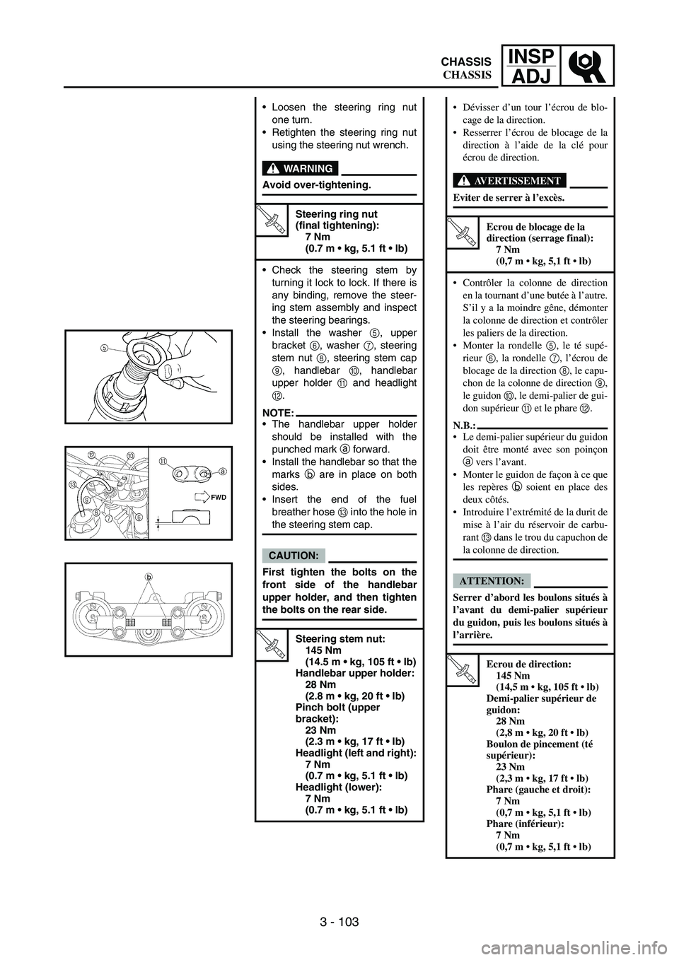
Check the steering stem by
turning it lock to lock. If there is
any binding, remove the steer-
ing stem assembly and inspect
the steering bearings.
Install the washer
5, upper
bracket
6, washer
7, steering
stem nut
8, steering stem cap
9, handlebar
0, handlebar
upper holder
A and headlight
B.
NOTE:The handlebar upper holder
should be installed with the
punched mark
a forward.
Install the handlebar so that the
marks
b are in place on both
sides.
Insert the end of the fuel
breather hose
C into the hole in
the steering stem cap.
CAUTION:
First tighten the bolts on the
front side of the handlebar
upper holder, and then tighten
the bolts on the rear side.
T R..
Steering stem nut:
145 Nm
(14.5 m kg, 105 ft lb)
Handlebar upper holder:
28 Nm
(2.8 m kg, 20 ft lb)
Pinch bolt (upper
bracket):
23 Nm
(2.3 m kg, 17 ft lb)
Headlight (left and right):
7 Nm
(0.7 m kg, 5.1 ft lb)
Headlight (lower):
7 Nm
(0.7 m kg, 5.1 ft lb)
Dévisser d’un tour l’écrou de blo-
cage de la direction.
Resserrer l’écrou de blocage de la
direction à l’aide de la clé pour
écrou de direction.
AVERTISSEMENT
Eviter de serrer à l’excès.
T R..
Ecrou de blocage de la
direction (serrage final):
7 Nm
(0,7 m kg, 5,1 ft lb)
Contrôler la colonne de direction
en la tournant d’une butée à l’autre.
S’il y a la moindre gêne, démonter
la colonne de direction et contrôler
les paliers de la direction.
Monter la rondelle 5, le té supé-
rieur 6, la rondelle 7, l’écrou de
blocage de la direction 8, le capu-
chon de la colonne de direction 9,
le guidon 0, le demi-palier de gui-
don supérieur A et le phare B.
N.B.:
Le demi-palier supérieur du guidon
doit être monté avec son poinçon
a vers l’avant.
Monter le guidon de façon à ce que
les repères b soient en place des
deux côtés.
Introduire l’extrémité de la durit de
mise à l’air du réservoir de carbu-
rant C dans le trou du capuchon de
la colonne de direction.
ATTENTION:
Serrer d’abord les boulons situés à
l’avant du demi-palier supérieur
du guidon, puis les boulons situés à
l’arrière.
T R..
Ecrou de direction:
145 Nm
(14,5 m kg, 105 ft lb)
Demi-palier supérieur de
guidon:
28 Nm
(2,8 m kg, 20 ft lb)
Boulon de pincement (té
supérieur):
23 Nm
(2,3 m kg, 17 ft lb)
Phare (gauche et droit):
7 Nm
(0,7 m kg, 5,1 ft lb)
Phare (inférieur):
7 Nm
(0,7 m kg, 5,1 ft lb)
CHASSIS
CHASSIS