Oil YAMAHA WR 250F 2007 Owners Manual
[x] Cancel search | Manufacturer: YAMAHA, Model Year: 2007, Model line: WR 250F, Model: YAMAHA WR 250F 2007Pages: 912, PDF Size: 23.95 MB
Page 618 of 912
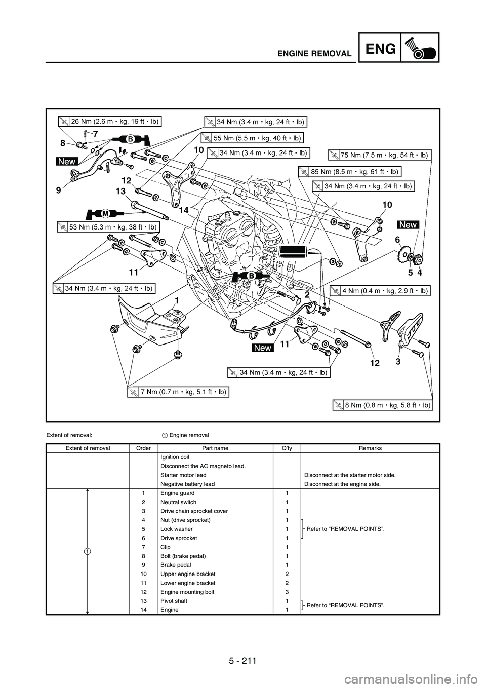
5 - 211
ENGENGINE REMOVAL
Extent of removal:
1 Engine removal
Extent of removal Order Part name Q’ty Remarks
Ignition coil
Disconnect the AC magneto lead.
Starter motor lead Disconnect at the starter motor side.
Negative battery lead Disconnect at the engine side.
1 Engine guard 1
2 Neutral switch 1
3 Drive chain sprocket cover 1
4 Nut (drive sprocket) 1
Refer to “REMOVAL POINTS”. 5 Lock washer 1
6 Drive sprocket 1
7 Clip 1
8 Bolt (brake pedal) 1
9 Brake pedal 1
10 Upper engine bracket 2
11 Lower engine bracket 2
12 Engine mounting bolt 3
13 Pivot shaft 1
Refer to “REMOVAL POINTS”.
14 Engine 1
1
Page 628 of 912
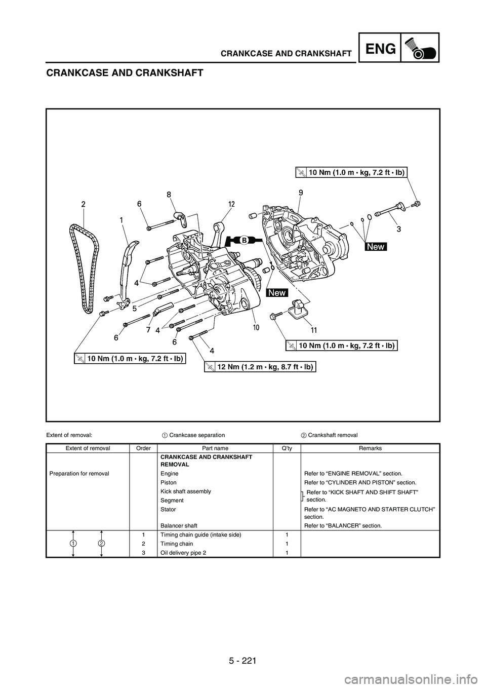
5 - 221
ENGCRANKCASE AND CRANKSHAFT
CRANKCASE AND CRANKSHAFT
Extent of removal:
1 Crankcase separation
2 Crankshaft removal
Extent of removal Order Part name Q’ty Remarks
CRANKCASE AND CRANKSHAFT
REMOVAL
Preparation for removal Engine Refer to “ENGINE REMOVAL” section.
Piston Refer to “CYLINDER AND PISTON” section.
Kick shaft assembly
Refer to “KICK SHAFT AND SHIFT SHAFT”
section.
Segment
Stator Refer to “AC MAGNETO AND STARTER CLUTCH”
section.
Balancer shaft Refer to “BALANCER” section.
1 Timing chain guide (intake side) 1
2 Timing chain 1
3 Oil delivery pipe 2 1
21
Page 632 of 912
![YAMAHA WR 250F 2007 Owners Manual 5 - 225
ENGCRANKCASE AND CRANKSHAFT
Extent of removal Order Part name Q’ty Remarks
4 Bolt [L = 45 mm (1.77 in)] 5
Refer to “REMOVAL POINTS”. 5 Bolt [L = 55 mm (2.17 in)] 1
6 Bolt [L = 70 mm (2.7 YAMAHA WR 250F 2007 Owners Manual 5 - 225
ENGCRANKCASE AND CRANKSHAFT
Extent of removal Order Part name Q’ty Remarks
4 Bolt [L = 45 mm (1.77 in)] 5
Refer to “REMOVAL POINTS”. 5 Bolt [L = 55 mm (2.17 in)] 1
6 Bolt [L = 70 mm (2.7](/img/51/52333/w960_52333-631.png)
5 - 225
ENGCRANKCASE AND CRANKSHAFT
Extent of removal Order Part name Q’ty Remarks
4 Bolt [L = 45 mm (1.77 in)] 5
Refer to “REMOVAL POINTS”. 5 Bolt [L = 55 mm (2.17 in)] 1
6 Bolt [L = 70 mm (2.76 in)] 3
7 Hose guide 1
8 Clutch cable holder 1
9 Right crankcase 1
10 Left crankcase 1
11 Oil strainer 1
12 Crankshaft 1 Use special tool.
Refer to “REMOVAL POINTS”.
2
1
Page 636 of 912
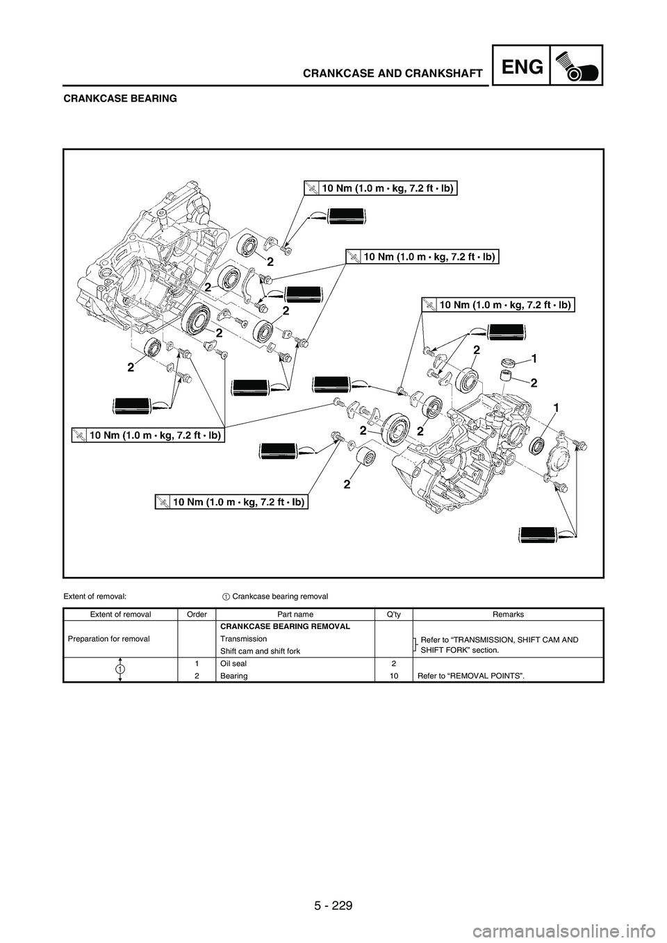
5 - 229
ENGCRANKCASE AND CRANKSHAFT
CRANKCASE BEARING
Extent of removal:
1 Crankcase bearing removal
Extent of removal Order Part name Q’ty Remarks
CRANKCASE BEARING REMOVAL
Preparation for removal Transmission
Refer to “TRANSMISSION, SHIFT CAM AND
SHIFT FORK” section.
Shift cam and shift fork
1 Oil seal 2
2 Bearing 10 Refer to “REMOVAL POINTS”.
1
Page 642 of 912
5 - 235
ENGCRANKCASE AND CRANKSHAFT
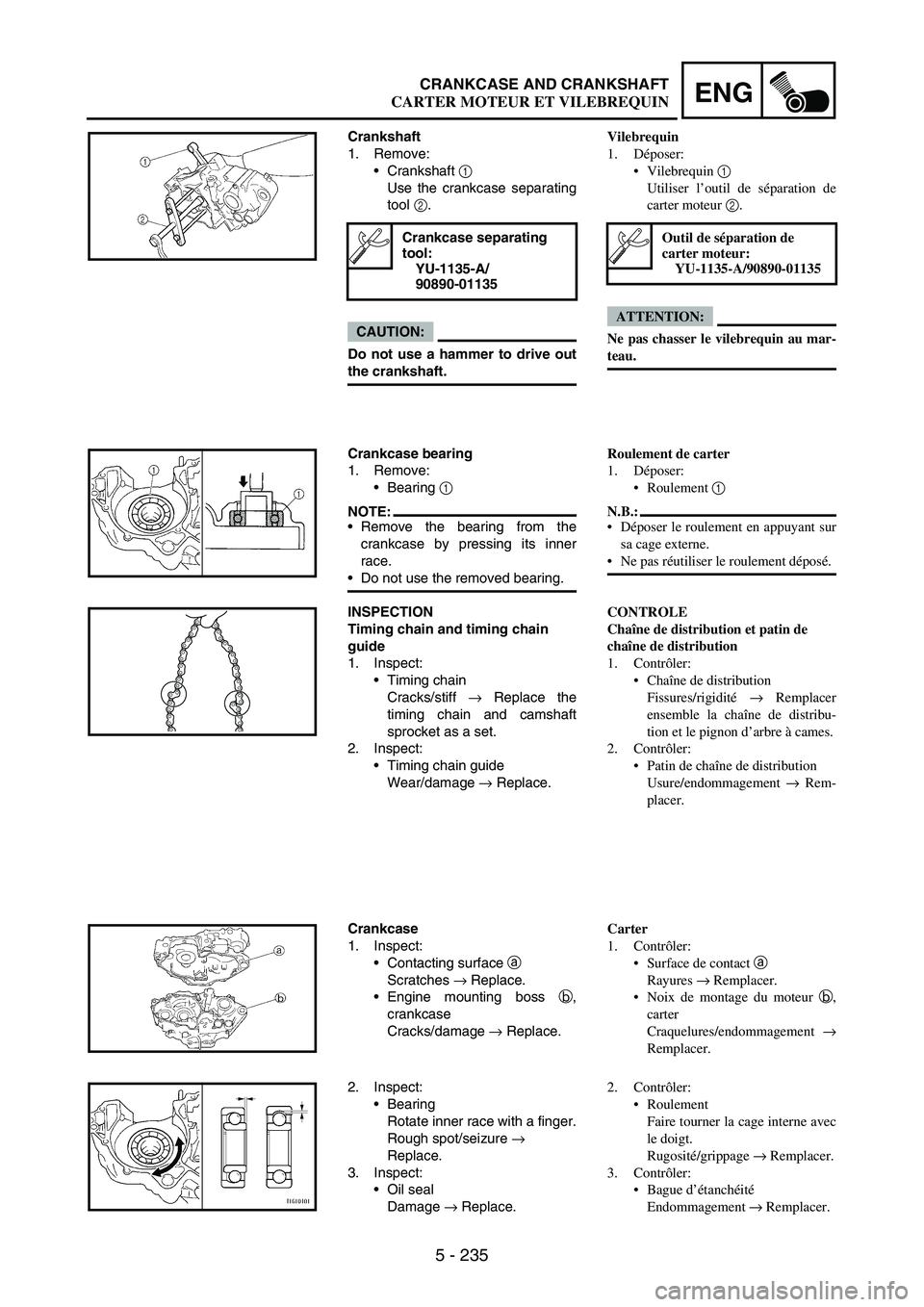
Crankshaft
1. Remove:
Crankshaft
1
Use the crankcase separating
tool
2.
CAUTION:
Do not use a hammer to drive out
the crankshaft.
Crankcase separating
tool:
YU-1135-A/
90890-01135
Crankcase bearing
1. Remove:
Bearing
1
NOTE:Remove the bearing from the
crankcase by pressing its inner
race.
Do not use the removed bearing.
INSPECTION
Timing chain and timing chain
guide
1. Inspect:
Timing chain
Cracks/stiff
→ Replace the
timing chain and camshaft
sprocket as a set.
2. Inspect:
Timing chain guide
Wear/damage
→ Replace.
Crankcase
1. Inspect:
Contacting surface
a
Scratches
→ Replace.
Engine mounting boss
b,
crankcase
Cracks/damage
→ Replace.
2. Inspect:
Bearing
Rotate inner race with a finger.
Rough spot/seizure
→
Replace.
3. Inspect:
Oil seal
Damage
→ Replace.
Vilebrequin
1. Déposer:
Vilebrequin 1
Utiliser l’outil de séparation de
carter moteur 2.
ATTENTION:
Ne pas chasser le vilebrequin au mar-
teau.
Outil de séparation de
carter moteur:
YU-1135-A/90890-01135
Roulement de carter
1. Déposer:
Roulement 1
N.B.:
Déposer le roulement en appuyant sur
sa cage externe.
Ne pas réutiliser le roulement déposé.
CONTROLE
Chaîne de distribution et patin de
chaîne de distribution
1. Contrôler:
Chaîne de distribution
Fissures/rigidité → Remplacer
ensemble la chaîne de distribu-
tion et le pignon d’arbre à cames.
2. Contrôler:
Patin de chaîne de distribution
Usure/endommagement → Rem-
placer.
Carter
1. Contrôler:
Surface de contact a
Rayures → Remplacer.
Noix de montage du moteur b,
carter
Craquelures/endommagement →
Remplacer.
2. Contrôler:
Roulement
Faire tourner la cage interne avec
le doigt.
Rugosité/grippage → Remplacer.
3. Contrôler:
Bague d’étanchéité
Endommagement → Remplacer.
CARTER MOTEUR ET VILEBREQUIN
Page 644 of 912
5 - 237
ENGCRANKCASE AND CRANKSHAFT
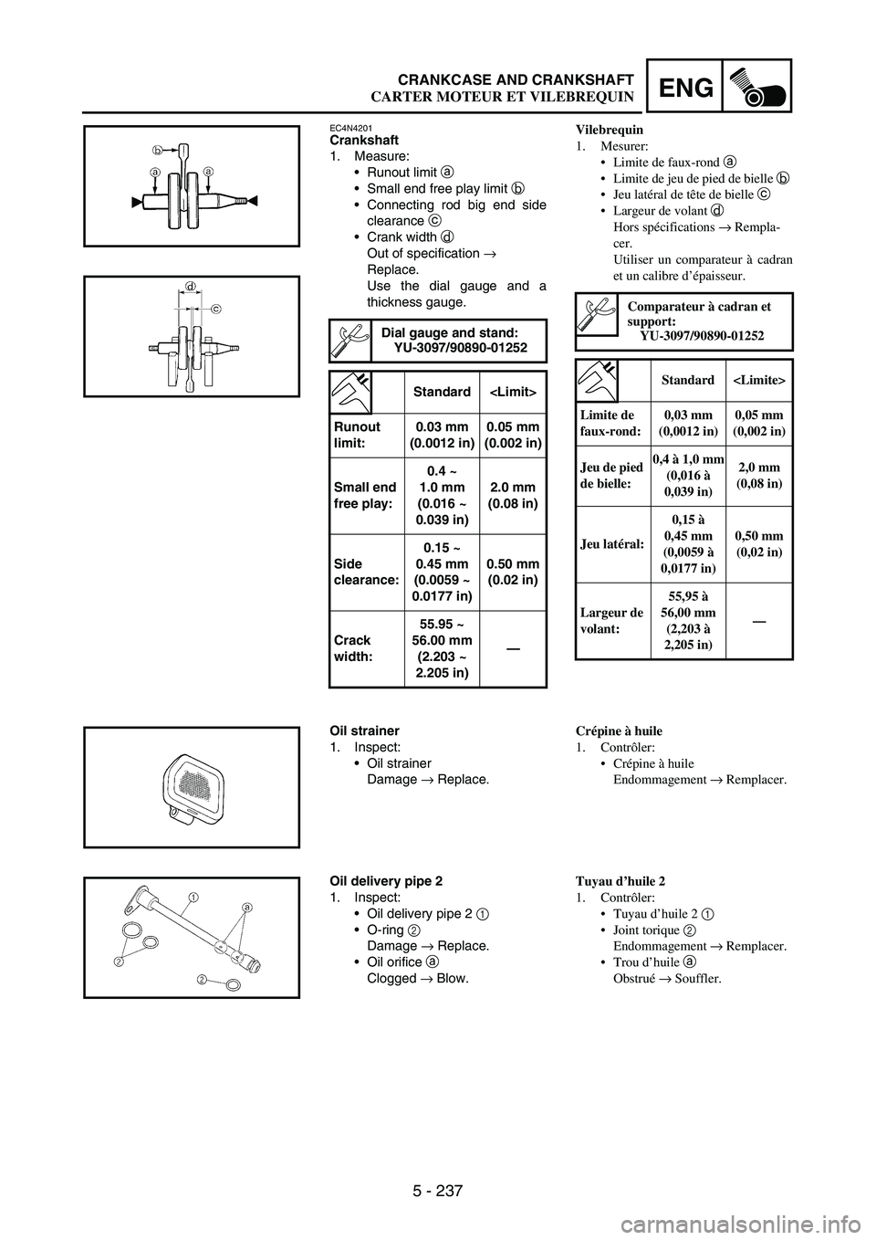
EC4N4201Crankshaft
1. Measure:
Runout limit
a
Small end free play limit
b
Connecting rod big end side
clearance
c
Crank width
d
Out of specification
→
Replace.
Use the dial gauge and a
thickness gauge.
Dial gauge and stand:
YU-3097/90890-01252
Standard
Runout
limit:0.03 mm
(0.0012 in)0.05 mm
(0.002 in)
Small end
free play:0.4 ~
1.0 mm
(0.016 ~
0.039 in)2.0 mm
(0.08 in)
Side
clearance:0.15 ~
0.45 mm
(0.0059 ~
0.0177 in)0.50 mm
(0.02 in)
Crack
width:55.95 ~
56.00 mm
(2.203 ~
2.205 in)—
Oil strainer
1. Inspect:
Oil strainer
Damage
→ Replace.
Oil delivery pipe 2
1. Inspect:
Oil delivery pipe 2
1
O-ring
2
Damage
→ Replace.
Oil orifice
a
Clogged
→ Blow.
Vilebrequin
1. Mesurer:
Limite de faux-rond a
Limite de jeu de pied de bielle b
Jeu latéral de tête de bielle c
Largeur de volant d
Hors spécifications → Rempla-
cer.
Utiliser un comparateur à cadran
et un calibre d’épaisseur.
Comparateur à cadran et
support:
YU-3097/90890-01252
Standard
Limite de
faux-rond:0,03 mm
(0,0012 in)0,05 mm
(0,002 in)
Jeu de pied
de bielle:0,4 à 1,0 mm
(0,016 à
0,039 in)2,0 mm
(0,08 in)
Jeu latéral:0,15 à
0,45 mm
(0,0059 à
0,0177 in)0,50 mm
(0,02 in)
Largeur de
volant:55,95 à
56,00 mm
(2,203 à
2,205 in)—
Crépine à huile
1. Contrôler:
Crépine à huile
Endommagement → Remplacer.
Tuyau d’huile 2
1. Contrôler:
Tuyau d’huile 2 1
Joint torique 2
Endommagement → Remplacer.
Trou d’huile a
Obstrué → Souffler.
CARTER MOTEUR ET VILEBREQUIN
Page 648 of 912
5 - 241
ENGCRANKCASE AND CRANKSHAFT
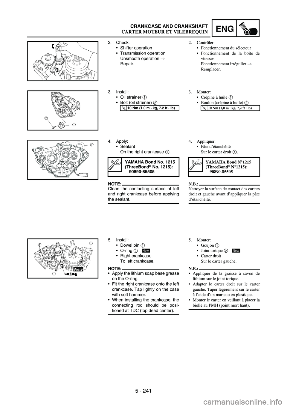
2. Check:
Shifter operation
Transmission operation
Unsmooth operation
→
Repair.
3. Install:
Oil strainer
1
Bolt (oil strainer)
2
T R..10 Nm (1.0 m · kg, 7.2 ft · lb)
4. Apply:
Sealant
On the right crankcase
1.
NOTE:Clean the contacting surface of left
and right crankcase before applying
the sealant.
YAMAHA Bond No. 1215
(ThreeBond® No. 1215):
90890-85505
5. Install:
Dowel pin
1
O-ring
2
Right crankcase
To left crankcase.
NOTE:Apply the lithium soap base grease
on the O-ring.
Fit the right crankcase onto the left
crankcase. Tap lightly on the case
with soft hammer.
When installing the crankcase, the
connecting rod should be posi-
tioned at TDC (top dead center).
New
2. Contrôler:
Fonctionnement du sélecteur
Fonctionnement de la boîte de
vitesses
Fonctionnement irrégulier →
Remplacer.
3. Monter:
Crépine à huile 1
Boulon (crépine à huile) 2
T R..10 Nm (1,0 m · kg, 7,2 ft · lb)
4. Appliquer:
Pâte d’étanchéité
Sur le carter droit 1.
N.B.:
Nettoyer la surface de contact des carters
droit et gauche avant d’appliquer la pâte
d’étanchéité.
YAMAHA Bond N°1215
(ThreeBond® N°1215):
90890-85505
5. Monter:
Goujon 1
Joint torique 2
Carter droit
Sur le carter gauche.
N.B.:
Appliquer de la graisse à savon de
lithium sur le joint torique.
Adapter le carter droit sur le carter
gauche. Taper légèrement sur le carter
à l’aide d’un marteau en plastique.
Monter le carter en veillant à placer la
bielle au PMH (point mort haut).
New
CARTER MOTEUR ET VILEBREQUIN
Page 650 of 912
5 - 243
ENGCRANKCASE AND CRANKSHAFT
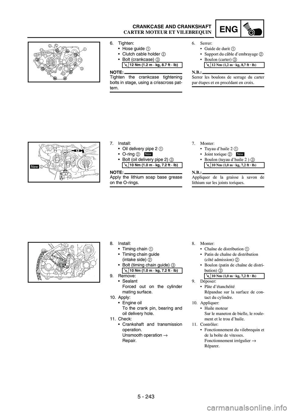
6. Tighten:
Hose guide
1
Clutch cable holder
2
Bolt (crankcase)
3
NOTE:Tighten the crankcase tightening
bolts in stage, using a crisscross pat-
tern.
T R..12 Nm (1.2 m · kg, 8.7 ft · lb)
7. Install:
Oil delivery pipe 2
1
O-ring
2
Bolt (oil delivery pipe 2)
3
NOTE:Apply the lithium soap base grease
on the O-rings.
T R..10 Nm (1.0 m · kg, 7.2 ft · lb)
New
8. Install:
Timing chain
1
Timing chain guide
(intake side)
2
Bolt (timing chain guide)
3
9. Remove:
Sealant
Forced out on the cylinder
mating surface.
10. Apply:
Engine oil
To the crank pin, bearing and
oil delivery hole.
11. Check:
Crankshaft and transmission
operation.
Unsmooth operation
→
Repair.
T R..10 Nm (1.0 m · kg, 7.2 ft · lb)
6. Serrer:
Guide de durit 1
Support du câble d’embrayage 2
Boulon (carter) 3
N.B.:
Serrer les boulons de serrage du carter
par étapes et en procédant en croix.
T R..12 Nm (1,2 m · kg, 8,7 ft · lb)
7. Monter:
Tuyau d’huile 2 1
Joint torique 2
Boulon (tuyau d’huile 2 ) 3
N.B.:
Appliquer de la graisse à savon de
lithium sur les joints toriques.
T R..10 Nm (1,0 m · kg, 7,2 ft · lb)
New
8. Monter:
Chaîne de distribution 1
Patin de chaîne de distribution
(côté admission) 2
Boulon (patin de chaîne de distri-
bution) 3
9. Déposer:
Pâte d’étanchéité
Répandue sur la surface de con-
tact du cylindre.
10. Appliquer:
Huile moteur
Sur le maneton de bielle, le roule-
ment et le trou d’huile.
11. Contrôler:
Fonctionnement du vilebrequin et
de la boîte de vitesses.
Fonctionnement irrégulier →
Réparer.
T R..10 Nm (1,0 m · kg, 7,2 ft · lb)
CARTER MOTEUR ET VILEBREQUIN
Page 658 of 912
5 - 251
ENGTRANSMISSION, SHIFT CAM AND SHIFT FORK
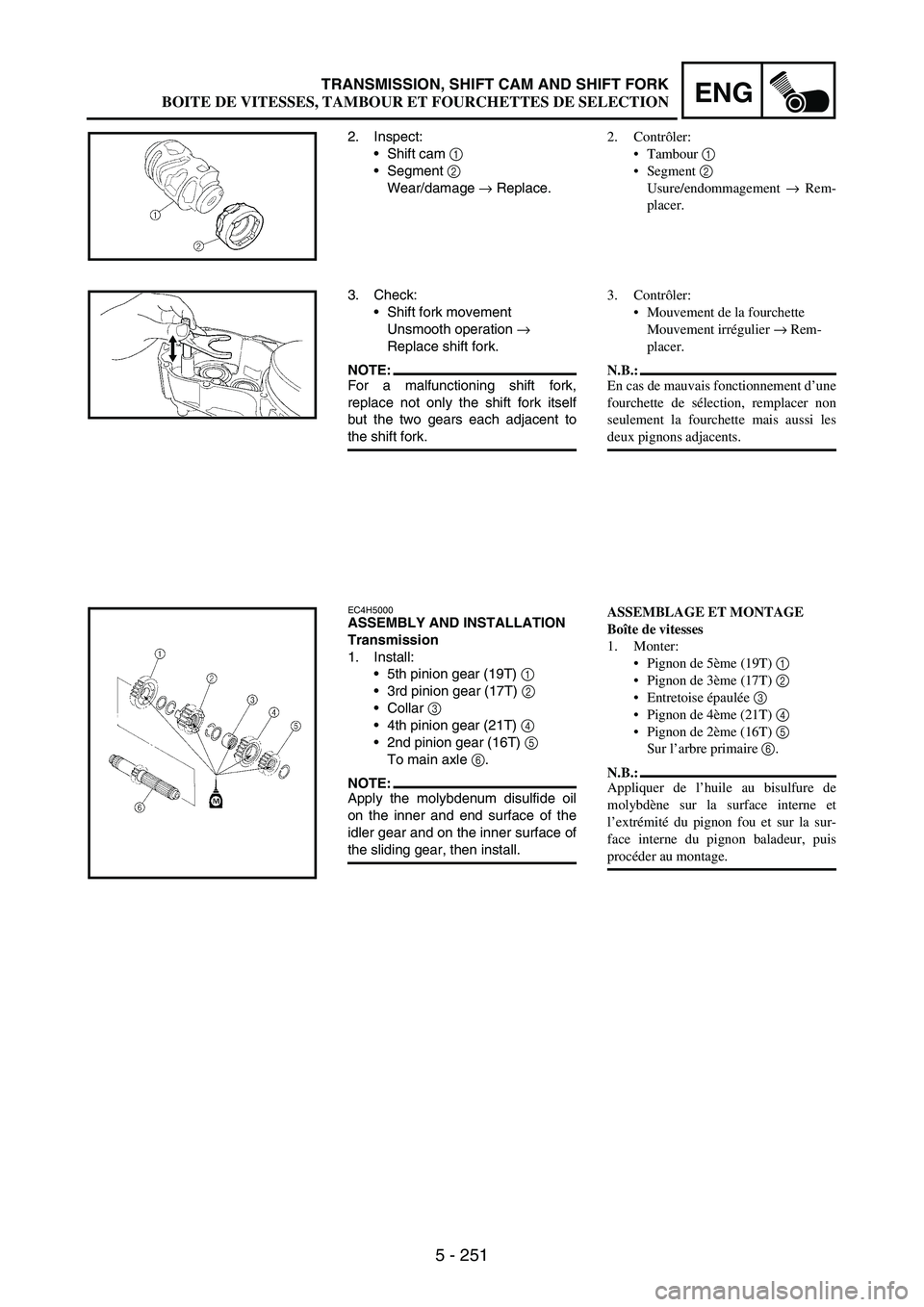
2. Inspect:
Shift cam
1
Segment
2
Wear/damage
→ Replace.
3. Check:
Shift fork movement
Unsmooth operation
→
Replace shift fork.
NOTE:For a malfunctioning shift fork,
replace not only the shift fork itself
but the two gears each adjacent to
the shift fork.
EC4H5000ASSEMBLY AND INSTALLATION
Transmission
1. Install:
5th pinion gear (19T)
1
3rd pinion gear (17T)
2
Collar
3
4th pinion gear (21T)
4
2nd pinion gear (16T)
5
To main axle
6.
NOTE:Apply the molybdenum disulfide oil
on the inner and end surface of the
idler gear and on the inner surface of
the sliding gear, then install.
2. Contrôler:
Tambour 1
Segment 2
Usure/endommagement → Rem-
placer.
3. Contrôler:
Mouvement de la fourchette
Mouvement irrégulier → Rem-
placer.
N.B.:
En cas de mauvais fonctionnement d’une
fourchette de sélection, remplacer non
seulement la fourchette mais aussi les
deux pignons adjacents.
ASSEMBLAGE ET MONTAGE
Boîte de vitesses
1. Monter:
Pignon de 5ème (19T) 1
Pignon de 3ème (17T) 2
Entretoise épaulée 3
Pignon de 4ème (21T) 4
Pignon de 2ème (16T) 5
Sur l’arbre primaire 6.
N.B.:
Appliquer de l’huile au bisulfure de
molybdène sur la surface interne et
l’extrémité du pignon fou et sur la sur-
face interne du pignon baladeur, puis
procéder au montage.
BOITE DE VITESSES, TAMBOUR ET FOURCHETTES DE SELECTION
Page 660 of 912
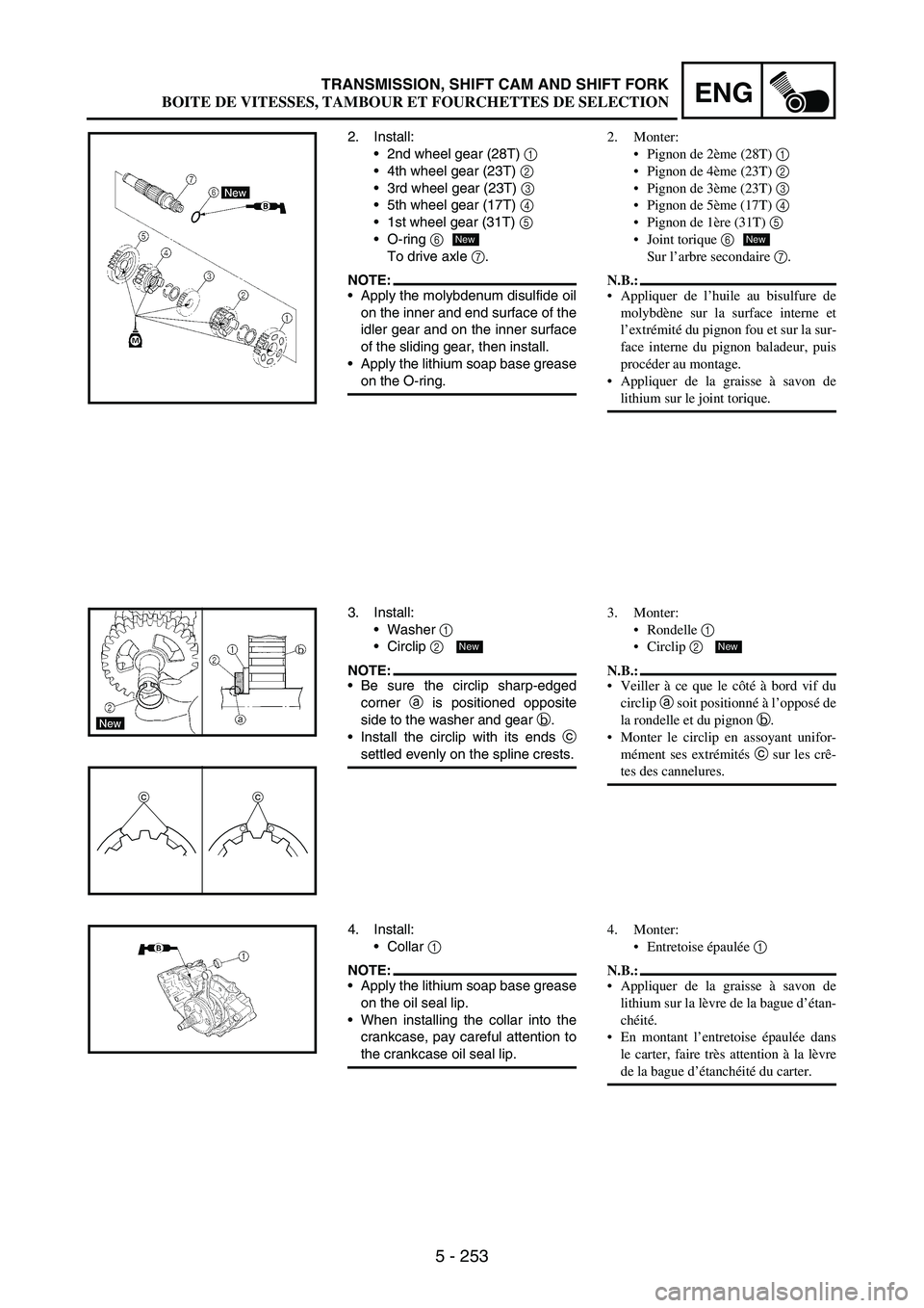
5 - 253
ENGTRANSMISSION, SHIFT CAM AND SHIFT FORK
2. Install:
2nd wheel gear (28T)
1
4th wheel gear (23T)
2
3rd wheel gear (23T)
3
5th wheel gear (17T)
4
1st wheel gear (31T)
5
O-ring
6
To drive axle
7.
NOTE:Apply the molybdenum disulfide oil
on the inner and end surface of the
idler gear and on the inner surface
of the sliding gear, then install.
Apply the lithium soap base grease
on the O-ring.
New
3. Install:
Washer
1
Circlip
2
NOTE:Be sure the circlip sharp-edged
corner
a is positioned opposite
side to the washer and gear
b.
Install the circlip with its ends
c
settled evenly on the spline crests.
cc
New
4. Install:
Collar
1
NOTE:Apply the lithium soap base grease
on the oil seal lip.
When installing the collar into the
crankcase, pay careful attention to
the crankcase oil seal lip.
2. Monter:
Pignon de 2ème (28T) 1
Pignon de 4ème (23T) 2
Pignon de 3ème (23T) 3
Pignon de 5ème (17T) 4
Pignon de 1ère (31T) 5
Joint torique 6
Sur l’arbre secondaire 7.
N.B.:
Appliquer de l’huile au bisulfure de
molybdène sur la surface interne et
l’extrémité du pignon fou et sur la sur-
face interne du pignon baladeur, puis
procéder au montage.
Appliquer de la graisse à savon de
lithium sur le joint torique.
New
3. Monter:
Rondelle 1
Circlip 2
N.B.:
Veiller à ce que le côté à bord vif du
circlip a soit positionné à l’opposé de
la rondelle et du pignon b.
Monter le circlip en assoyant unifor-
mément ses extrémités c sur les crê-
tes des cannelures.
New
4. Monter:
Entretoise épaulée 1
N.B.:
Appliquer de la graisse à savon de
lithium sur la lèvre de la bague d’étan-
chéité.
En montant l’entretoise épaulée dans
le carter, faire très attention à la lèvre
de la bague d’étanchéité du carter.
BOITE DE VITESSES, TAMBOUR ET FOURCHETTES DE SELECTION