sensor YAMAHA WR 250F 2009 Owners Manual
[x] Cancel search | Manufacturer: YAMAHA, Model Year: 2009, Model line: WR 250F, Model: YAMAHA WR 250F 2009Pages: 224, PDF Size: 13.93 MB
Page 8 of 224
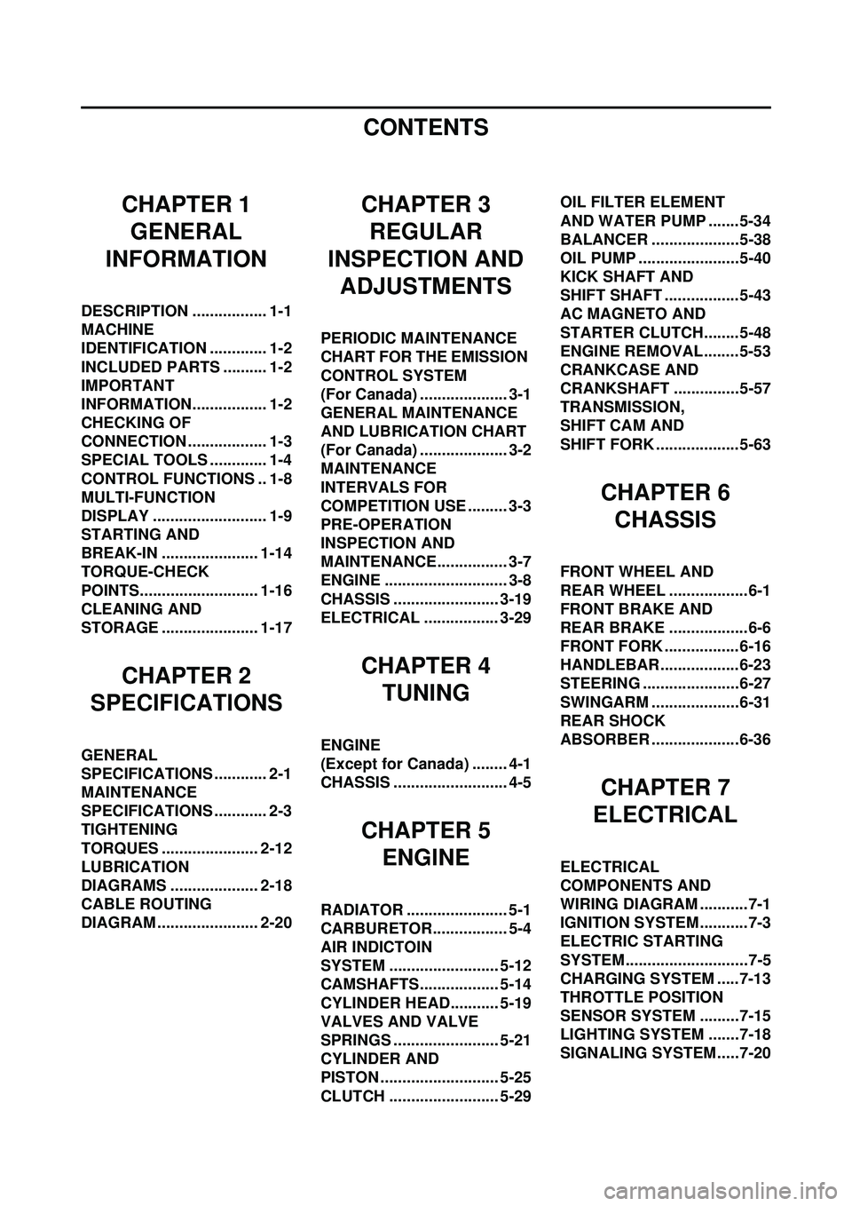
CONTENTS
CHAPTER 1GENERAL
INFORMATION
DESCRIPTION ................. 1-1
MACHINE
IDENTIFICATION ............. 1-2
INCLUDED PARTS .......... 1-2
IMPORTANT
INFORMATION................. 1-2
CHECKING OF
CONNECTION .................. 1-3
SPECIAL TOOLS ............. 1-4
CONTROL FUNCTIONS .. 1-8
MULTI-FUNCTION
DISPLAY .......................... 1-9
STARTING AND
BREAK-IN ...................... 1-14
TORQUE-CHECK
POINTS........................... 1-16
CLEANING AND
STORAGE ...................... 1-17
CHAPTER 2
SPECIFICATIONS
GENERAL
SPECIFICATIONS ............ 2-1
MAINTENANCE
SPECIFICATIONS ............ 2-3
TIGHTENING
TORQUES ...................... 2-12
LUBRICATION
DIAGRAMS .................... 2-18
CABLE ROUTING
DIAGRAM ....................... 2-20
CHAPTER 3 REGULAR
INSPECTION AND ADJUSTMENTS
PERIODIC MAINTENANCE
CHART FOR THE EMISSION
CONTROL SYSTEM
(For Canada) .................... 3-1
GENERAL MAINTENANCE
AND LUBRICATION CHART
(For Canada) .................... 3-2
MAINTENANCE
INTERVALS FOR
COMPETITION USE ......... 3-3
PRE-OPERATION
INSPECTION AND
MAINTENANCE................ 3-7
ENGINE ............................ 3-8
CHASSIS ........................ 3-19
ELECTRICAL ................. 3-29
CHAPTER 4 TUNING
ENGINE
(Except for Canada) ........ 4-1
CHASSIS .......................... 4-5
CHAPTER 5ENGINE
RADIATOR ....................... 5-1
CARBURETOR................. 5-4
AIR INDICTOIN
SYSTEM ......................... 5-12
CAMSHAFTS.................. 5-14
CYLINDER HEAD........... 5-19
VALVES AND VALVE
SPRINGS ........................ 5-21
CYLINDER AND
PISTON ........................... 5-25
CLUTCH ......................... 5-29 OIL FILTER ELEMENT
AND WATER PUMP .......5-34
BALANCER ....................5-38
OIL PUMP .......................5-40
KICK SHAFT AND
SHIFT SHAFT ................. 5-43
AC MAGNETO AND
STARTER CLUTCH........5-48
ENGINE REMOVAL........ 5-53
CRANKCASE AND
CRANKSHAFT ...............5-57
TRANSMISSION,
SHIFT CAM AND
SHIFT FORK ................... 5-63
CHAPTER 6
CHASSIS
FRONT WHEEL AND
REAR WHEEL ..................6-1
FRONT BRAKE AND
REAR BRAKE ..................6-6
FRONT FORK ................. 6-16
HANDLEBAR..................6-23
STEERING ......................6-27
SWINGARM ....................6-31
REAR SHOCK
ABSORBER ....................6-36
CHAPTER 7
ELECTRICAL
ELECTRICAL
COMPONENTS AND
WIRING DIAGRAM ...........7-1
IGNITION SYSTEM...........7-3
ELECTRIC STARTING
SYSTEM............................7-5
CHARGING SYSTEM .....7-13
THROTTLE POSITION
SENSOR SYSTEM .........7-15
LIGHTING SYSTEM .......7-18
SIGNALING SYSTEM.....7-20
Page 40 of 224
2-15
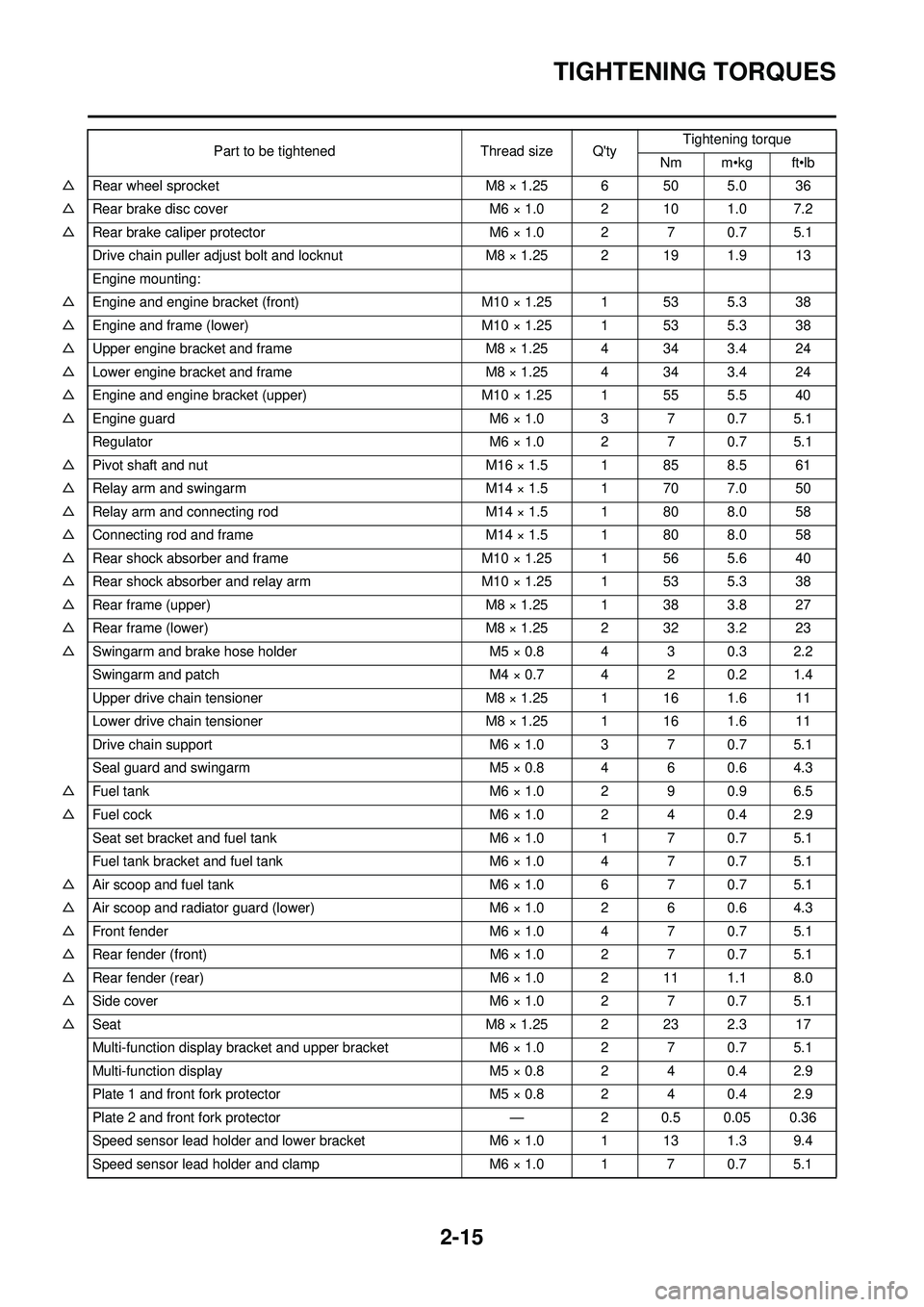
TIGHTENING TORQUES
△Rear wheel sprocket M8 × 1.25 6 50 5.0 36
△ Rear brake disc cover M6 × 1.0 2 10 1.0 7.2
△ Rear brake caliper protector M6 × 1.0 2 7 0.7 5.1
Drive chain puller adjust bolt and locknut M8 × 1.25 2 19 1.9 13
Engine mounting:
△ Engine and engine bracket (front) M10 × 1.25 1 53 5.3 38
△ Engine and frame (lower) M10 × 1.25 1 53 5.3 38
△ Upper engine bracket and frame M8 × 1.25 4 34 3.4 24
△ Lower engine bracket and frame M8 × 1.25 4 34 3.4 24
△ Engine and engine bracket (upper) M10 × 1.25 1 55 5.5 40
△ Engine guard M6 × 1.0 3 7 0.7 5.1
Regulator M6 × 1.0 2 7 0.7 5.1
△ Pivot shaft and nut M16 × 1.5 1 85 8.5 61
△ Relay arm and swingarm M14 × 1.5 1 70 7.0 50
△ Relay arm and connecting rod M14 × 1.5 1 80 8.0 58
△ Connecting rod and frame M14 × 1.5 1 80 8.0 58
△ Rear shock absorber and frame M10 × 1.25 1 56 5.6 40
△ Rear shock absorber and relay arm M10 × 1.25 1 53 5.3 38
△ Rear frame (upper) M8 × 1.25 1 38 3.8 27
△ Rear frame (lower) M8 × 1.25 2 32 3.2 23
△ Swingarm and brake hose holder M5 × 0.8 4 3 0.3 2.2
Swingarm and patch M4 × 0.7 4 2 0.2 1.4
Upper drive chain tensioner M8 × 1.25 1 16 1.6 11
Lower drive chain tensioner M8 × 1.25 1 16 1.6 11
Drive chain support M6 × 1.0 3 7 0.7 5.1
Seal guard and swingarm M5 × 0.8 4 6 0.6 4.3
△ Fuel tank M6 × 1.0 2 9 0.9 6.5
△ Fuel cock M6 × 1.0 2 4 0.4 2.9
Seat set bracket and fuel tank M6 × 1.0 1 7 0.7 5.1
Fuel tank bracket and fuel tank M6 × 1.0 4 7 0.7 5.1
△ Air scoop and fuel tank M6 × 1.0 6 7 0.7 5.1
△ Air scoop and radiator guard (lower) M6 × 1.0 2 6 0.6 4.3
△ Front fender M6 × 1.0 4 7 0.7 5.1
△ Rear fender (front) M6 × 1.0 2 7 0.7 5.1
△ Rear fender (rear) M6 × 1.0 2 11 1.1 8.0
△ Side cover M6 × 1.0 2 7 0.7 5.1
△ Seat M8 × 1.25 2 23 2.3 17
Multi-function display bracket and upper bracket M6 × 1.0 2 7 0.7 5.1
Multi-function display M5 × 0.8 2 4 0.4 2.9
Plate 1 and front fork protector M5 × 0.8 2 4 0.4 2.9
Plate 2 and front fork protector — 2 0.5 0.05 0.36
Speed sensor lead holder and lower bracket M6 × 1.0 1 13 1.3 9.4
Speed sensor lead holder and clamp M6 × 1.0 1 7 0.7 5.1 Part to be tightened Thread size Q'ty
Tightening torque
Nm m•kg ft•lb
Page 46 of 224
2-20
CABLE ROUTING DIAGRAM
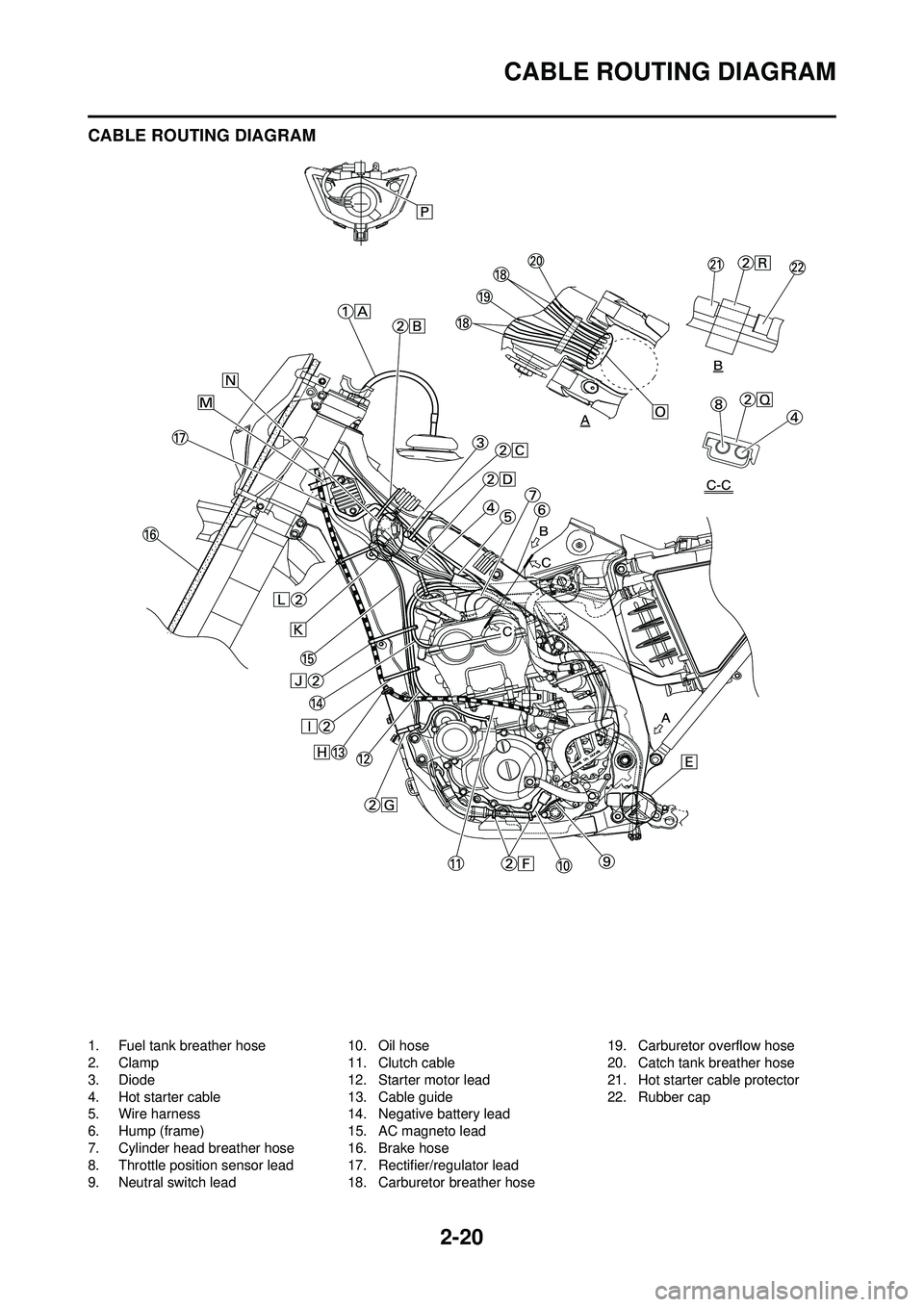
CABLE ROUTING DIAGRAM
1. Fuel tank breather hose
2. Clamp
3. Diode
4. Hot starter cable
5. Wire harness
6. Hump (frame)
7. Cylinder head breather hose
8. Throttle position sensor lead
9. Neutral switch lead10. Oil hose
11. Clutch cable
12. Starter motor lead
13. Cable guide
14. Negative battery lead
15. AC magneto lead
16. Brake hose
17. Rectifier/regulator lead
18. Carburetor breather hose19. Carburetor overflow hose
20. Catch tank breather hose
21. Hot starter cable protector
22. Rubber cap
Page 47 of 224
2-21
CABLE ROUTING DIAGRAM
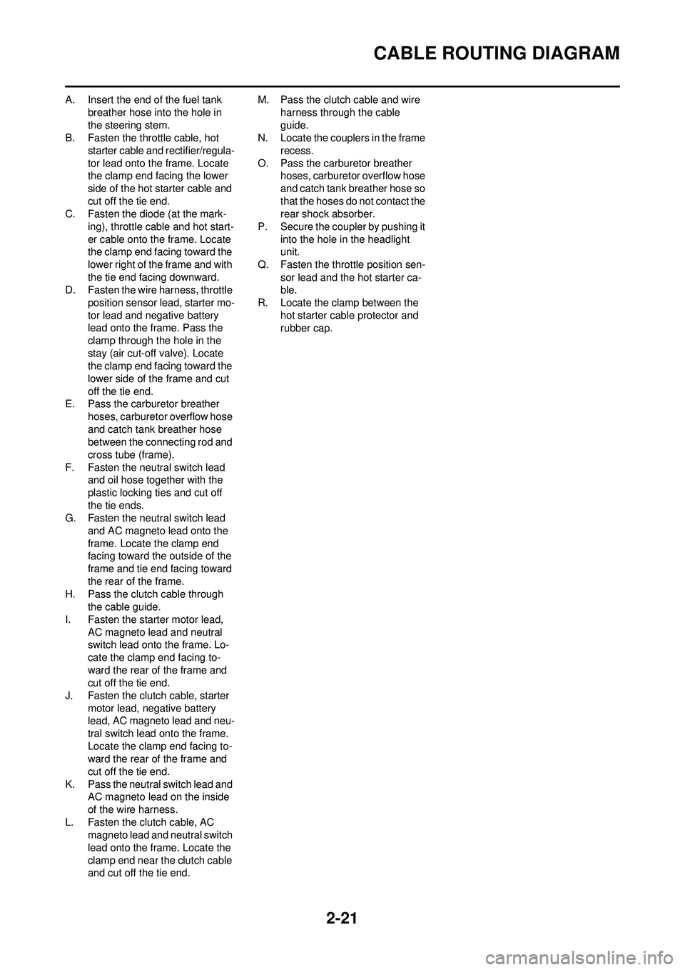
A. Insert the end of the fuel tank breather hose into the hole in
the steering stem.
B. Fasten the throttle cable, hot
starter cable and rectifier/regula-
tor lead onto the frame. Locate
the clamp end facing the lower
side of the hot starter cable and
cut off the tie end.
C. Fasten the diode (at the mark-
ing), throttle cable and hot start-
er cable onto the frame. Locate
the clamp end facing toward the
lower right of the frame and with
the tie end facing downward.
D. Fasten the wire harness, throttle
position sensor lead, starter mo-
tor lead and negative battery
lead onto the frame. Pass the
clamp through the hole in the
stay (air cut-off valve). Locate
the clamp end facing toward the
lower side of the frame and cut
off the tie end.
E. Pass the carburetor breather
hoses, carburetor overflow hose
and catch tank breather hose
between the connecting rod and
cross tube (frame).
F. Fasten the neutral switch lead and oil hose together with the
plastic locking ties and cut off
the tie ends.
G. Fasten the neutral switch lead
and AC magneto lead onto the
frame. Locate the clamp end
facing toward the outside of the
frame and tie end facing toward
the rear of the frame.
H. Pass the clutch cable through the cable guide.
I. Fasten the starter motor lead, AC magneto lead and neutral
switch lead onto the frame. Lo-
cate the clamp end facing to-
ward the rear of the frame and
cut off the tie end.
J. Fasten the clutch cable, starter motor lead, negative battery
lead, AC magneto lead and neu-
tral switch lead onto the frame.
Locate the clamp end facing to-
ward the rear of the frame and
cut off the tie end.
K. Pass the neutral switch lead and AC magneto lead on the inside
of the wire harness.
L. Fasten the clutch cable, AC magneto lead and neutral switch
lead onto the frame. Locate the
clamp end near the clutch cable
and cut off the tie end. M. Pass the clutch cable and wire
harness through the cable
guide.
N. Locate the couplers in the frame
recess.
O. Pass the carburetor breather hoses, carburetor overflow hose
and catch tank breather hose so
that the hoses do not contact the
rear shock absorber.
P. Secure the coupler by pushing it into the hole in the headlight
unit.
Q. Fasten the throttle position sen- sor lead and the hot starter ca-
ble.
R. Locate the clamp between the hot starter cable protector and
rubber cap.
Page 52 of 224
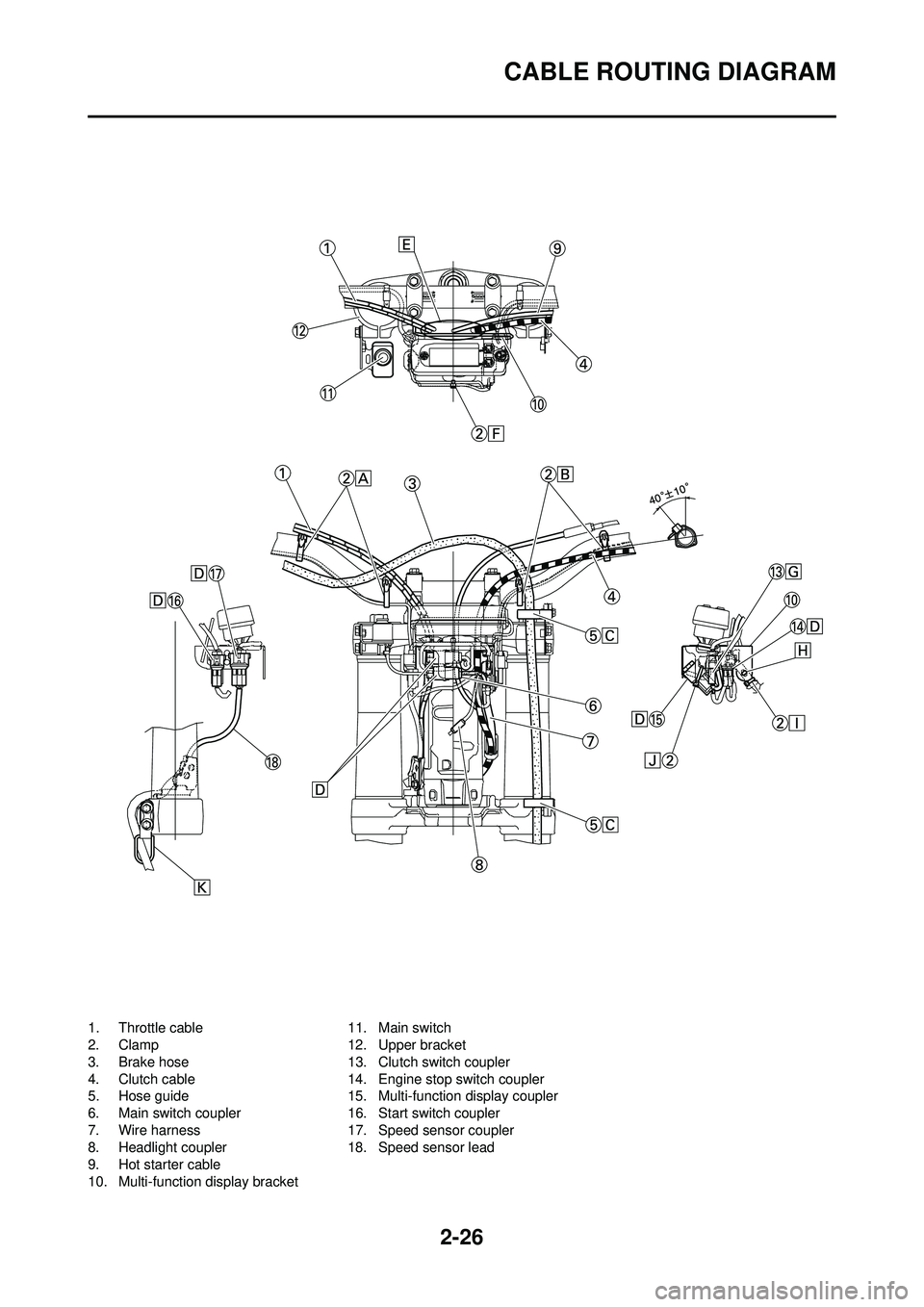
2-26
CABLE ROUTING DIAGRAM
1. Throttle cable
2. Clamp
3. Brake hose
4. Clutch cable
5. Hose guide
6. Main switch coupler
7. Wire harness
8. Headlight coupler
9. Hot starter cable
10. Multi-function display bracket11. Main switch
12. Upper bracket
13. Clutch switch coupler
14. Engine stop switch coupler
15. Multi-function display coupler
16. Start switch coupler
17. Speed sensor coupler
18. Speed sensor lead
Page 53 of 224
2-27
CABLE ROUTING DIAGRAM
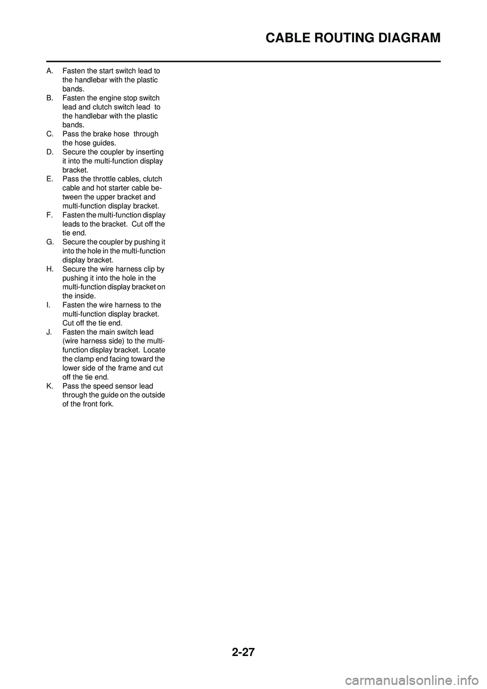
A. Fasten the start switch lead to the handlebar with the plastic
bands.
B. Fasten the engine stop switch
lead and clutch switch lead to
the handlebar with the plastic
bands.
C. Pass the brake hose through the hose guides.
D. Secure the coupler by inserting
it into the multi-function display
bracket.
E. Pass the throttle cables, clutch
cable and hot starter cable be-
tween the upper bracket and
multi-function display bracket.
F. Fasten the multi-function display leads to the bracket. Cut off the
tie end.
G. Secure the coupler by pushing it into the hole in the multi-function
display bracket.
H. Secure the wire harness clip by pushing it into the hole in the
multi-function display bracket on
the inside.
I. Fasten the wire harness to the multi-function display bracket.
Cut off the tie end.
J. Fasten the main switch lead (wire harness side) to the multi-
function display bracket. Locate
the clamp end facing toward the
lower side of the frame and cut
off the tie end.
K. Pass the speed sensor lead through the guide on the outside
of the front fork.
Page 100 of 224
5-4
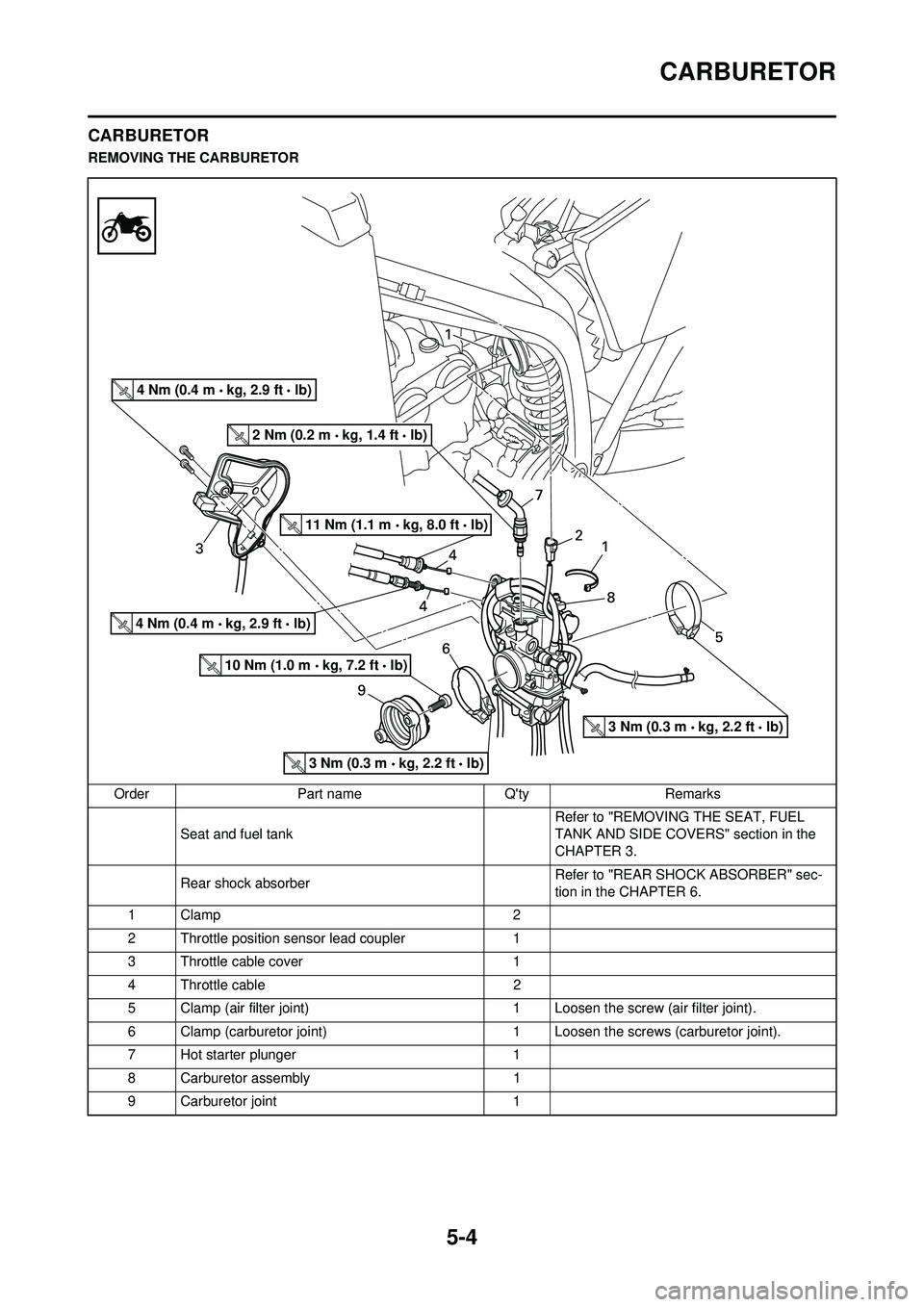
CARBURETOR
CARBURETOR
REMOVING THE CARBURETOROrder Part name Q'ty Remarks Seat and fuel tank Refer to "REMOVING THE SEAT, FUEL
TANK AND SIDE COVERS" section in the
CHAPTER 3.
Rear shock absorber Refer to "REAR SHOCK ABSORBER" sec-
tion in the CHAPTER 6.
1Clamp 2
2 Throttle position sensor lead coupler 1
3 Throttle cable cover 1
4 Throttle cable 2
5 Clamp (air filter joint) 1 Loosen the screw (air filter joint).
6 Clamp (carburetor joint) 1 Loosen the screws (carburetor joint).
7 Hot starter plunger 1
8 Carburetor assembly 1
9 Carburetor joint 1
4 Nm (0.4 m kg, 2.9 ft lb)
2 Nm (0.2 m kg, 1.4 ft lb)
11 Nm (1.1 m kg, 8.0 ft lb)
4 Nm (0.4 m kg, 2.9 ft lb)
10 Nm (1.0 m kg, 7.2 ft lb)
3 Nm (0.3 m kg, 2.2 ft lb)
3 Nm (0.3 m kg, 2.2 ft lb)
Page 103 of 224
5-7
CARBURETOR
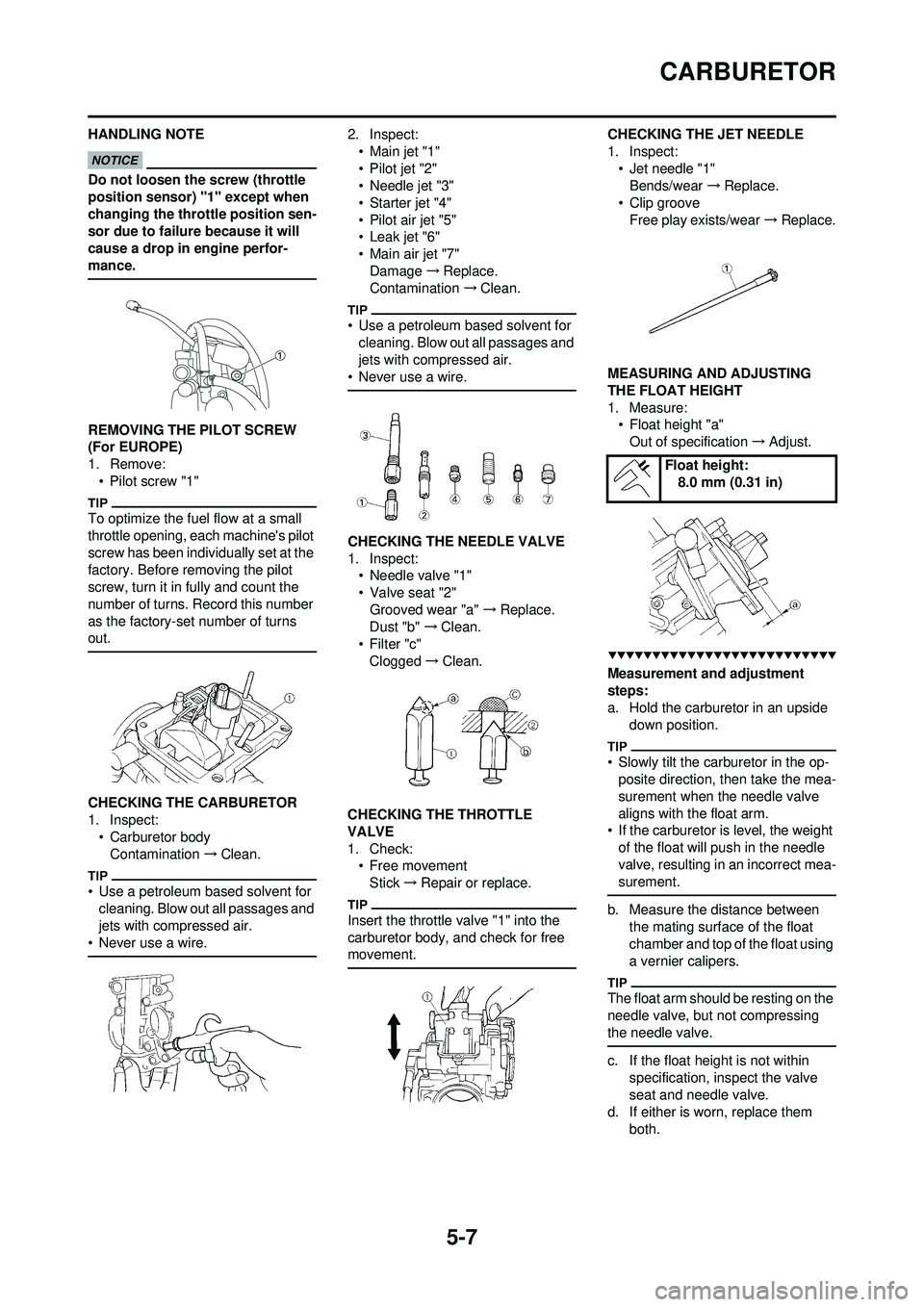
HANDLING NOTE
Do not loosen the screw (throttle
position sensor) "1" except when
changing the throttle position sen-
sor due to failure because it will
cause a drop in engine perfor-
mance.
REMOVING THE PILOT SCREW
(For EUROPE)
1. Remove:• Pilot screw "1"
To optimize the fuel flow at a small
throttle opening, each machine's pilot
screw has been individually set at the
factory. Before removing the pilot
screw, turn it in fully and count the
number of turns. Record this number
as the factory-set number of turns
out.
CHECKING THE CARBURETOR
1. Inspect:• Carburetor body
Contamination →Clean.
• Use a petroleum based solvent for
cleaning. Blow out all passages and
jets with compressed air.
• Never use a wire.
2. Inspect: •Main jet "1"
• Pilot jet "2"
• Needle jet "3"
• Starter jet "4"
• Pilot air jet "5"
•Leak jet "6"
• Main air jet "7"Damage →Replace.
Contamination →Clean.
• Use a petroleum based solvent for
cleaning. Blow out all passages and
jets with compressed air.
• Never use a wire.
CHECKING THE NEEDLE VALVE
1. Inspect: • Needle valve "1"
• Valve seat "2"
Grooved wear "a" →Replace.
Dust "b" →Clean.
•Filter "c" Clogged →Clean.
CHECKING THE THROTTLE
VALVE
1. Check: • Free movement
Stick →Repair or replace.
Insert the throttle valve "1" into the
carburetor body, and check for free
movement.
CHECKING THE JET NEEDLE
1. Inspect:
•Jet needle "1"Bends/wear →Replace.
• Clip groove Free play exists/wear →Replace.
MEASURING AND ADJUSTING
THE FLOAT HEIGHT
1. Measure: • Float height "a"
Out of specification →Adjust.
Measurement and adjustment
steps:
a. Hold the carburetor in an upside
down position.
• Slowly tilt the carburetor in the op-posite direction, then take the mea-
surement when the needle valve
aligns with the float arm.
• If the carburetor is level, the weight
of the float will push in the needle
valve, resulting in an incorrect mea-
surement.
b. Measure the distance between the mating surface of the float
chamber and top of the float using
a vernier calipers.
The float arm should be resting on the
needle valve, but not compressing
the needle valve.
c. If the float height is not within specification, inspect the valve
seat and needle valve.
d. If either is worn, replace them
both.
Float height:8.0 mm (0.31 in)
Page 105 of 224
5-9
CARBURETOR
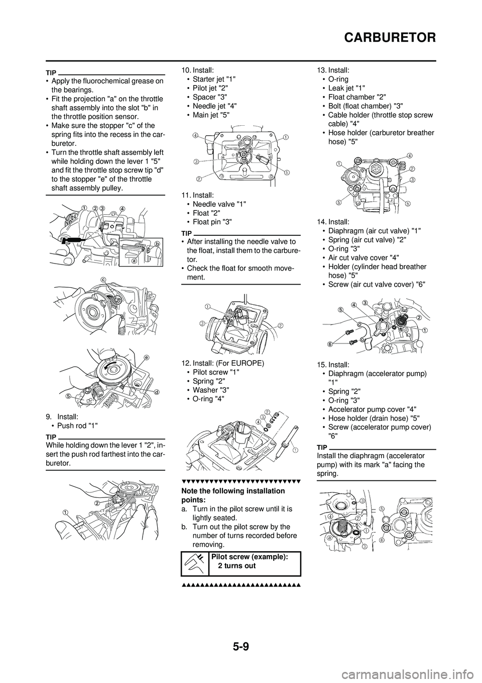
• Apply the fluorochemical grease on the bearings.
• Fit the projection "a" on the throttle shaft assembly into the slot "b" in
the throttle position sensor.
• Make sure the stopper "c" of the spring fits into the recess in the car-
buretor.
• Turn the throttle shaft assembly left while holding down the lever 1 "5"
and fit the throttle stop screw tip "d"
to the stopper "e" of the throttle
shaft assembly pulley.
9. Install:• Push rod "1"
While holding down the lever 1 "2", in-
sert the push rod farthest into the car-
buretor.
10. Install:• Starter jet "1"
• Pilot jet "2"
•Spacer "3"
• Needle jet "4"
•Main jet "5"
11. Install: • Needle valve "1"
• Float "2"
• Float pin "3"
• After installing the needle valve to the float, install them to the carbure-
tor.
• Check the float for smooth move-
ment.
12. Install: (For EUROPE)• Pilot screw "1"
• Spring "2"
•Washer "3"
• O-ring "4"
Note the following installation
points:
a. Turn in the pilot screw until it is
lightly seated.
b. Turn out the pilot screw by the number of turns recorded before
removing.
13. Install:
• O-ring
• Leak jet "1"
• Float chamber "2"
• Bolt (float chamber) "3"
• Cable holder (throttle stop screw cable) "4"
• Hose holder (carburetor breather hose) "5"
14. Install: • Diaphragm (air cut valve) "1"
• Spring (air cut valve) "2"
• O-ring "3"
• Air cut valve cover "4"
• Holder (cylinder head breather hose) "5"
• Screw (air cut valve cover) "6"
15. Install: • Diaphragm (accelerator pump)
"1"
• Spring "2"
• O-ring "3"
• Accelerator pump cover "4"
• Hose holder (drain hose) "5"
• Screw (accelerator pump cover) "6"
Install the diaphragm (accelerator
pump) with its mark "a" facing the
spring.
Pilot screw (example): 2 turns out
Page 107 of 224
5-11
CARBURETOR
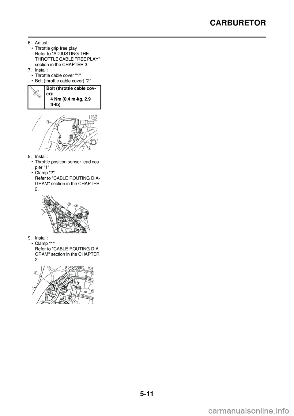
6. Adjust:• Throttle grip free playRefer to "ADJUSTING THE
THROTTLE CABLE FREE PLAY"
section in the CHAPTER 3.
7. Install: • Throttle cable cover "1"
• Bolt (throttle cable cover) "2"
8. Install: • Throttle position sensor lead cou-
pler "1"
•Clamp "2" Refer to "CABLE ROUTING DIA-
GRAM" section in the CHAPTER
2.
9. Install: •Clamp "1"Refer to "CABLE ROUTING DIA-
GRAM" section in the CHAPTER
2. Bolt (throttle cable cov-
er):
4 Nm (0.4 m•kg, 2.9
ft•lb)