stop start YAMAHA WR 250F 2014 User Guide
[x] Cancel search | Manufacturer: YAMAHA, Model Year: 2014, Model line: WR 250F, Model: YAMAHA WR 250F 2014Pages: 230, PDF Size: 13.01 MB
Page 58 of 230
2-27
CABLE ROUTING DIAGRAM
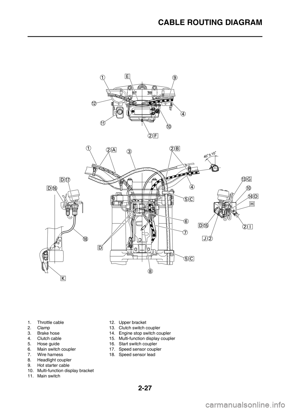
1. Throttle cable
2. Clamp
3. Brake hose
4. Clutch cable
5. Hose guide
6. Main switch coupler
7. Wire harness
8. Headlight coupler
9. Hot starter cable
10. Multi-function display bracket
11. Main switch12. Upper bracket
13. Clutch switch coupler
14. Engine stop switch coupler
15. Multi-function display coupler
16. Start switch coupler
17. Speed sensor coupler
18. Speed sensor lead
Page 59 of 230

2-28
CABLE ROUTING DIAGRAM
A. Fasten the start switch lead to
the handlebar with the plastic
bands.
B. Fasten the engine stop switch
lead and clutch switch lead to
the handlebar with the plastic
bands.
C. Pass the brake hose through
the hose guides.
D. Secure the coupler by inserting
it into the multi-function display
bracket.
E. Pass the throttle cables, clutch
cable and hot starter cable be-
tween the upper bracket and
multi-function display bracket.
F. Fasten the multi-function display
leads to the bracket. Cut off the
tie end.
G. Secure the coupler by pushing it
into the hole in the multi-function
display bracket.
H. Secure the wire harness clip by
pushing it into the hole in the
multi-function display bracket on
the inside.
I. Fasten the wire harness to the
multi-function display bracket.
Cut off the tie end.
J. Fasten the main switch lead
(wire harness side) to the multi-
function display bracket. Locate
the clamp end facing toward the
lower side of the frame and cut
off the tie end.
K. Pass the speed sensor lead
through the guide on the outside
of the front fork.
Page 73 of 230
3-14
ENGINE
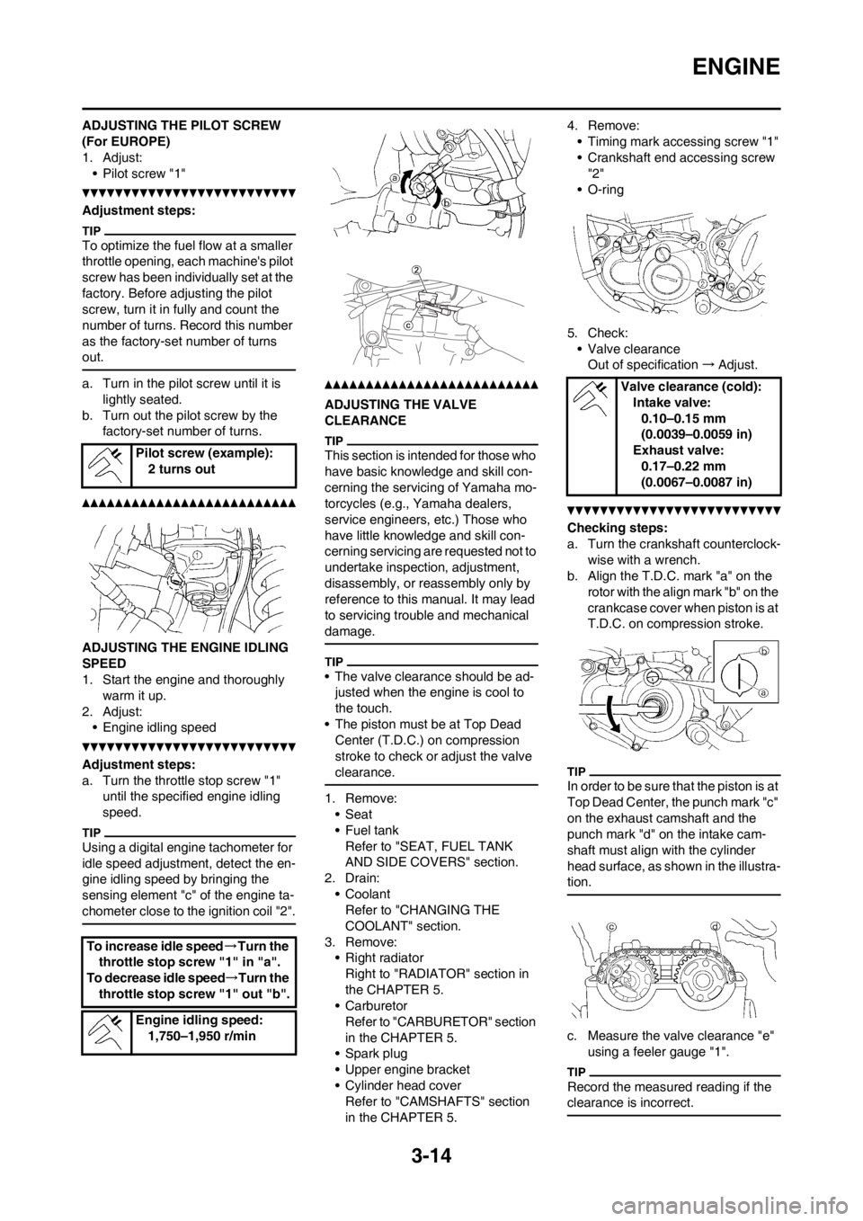
ADJUSTING THE PILOT SCREW
(For EUROPE)
1. Adjust:
• Pilot screw "1"
Adjustment steps:
To optimize the fuel flow at a smaller
throttle opening, each machine's pilot
screw has been individually set at the
factory. Before adjusting the pilot
screw, turn it in fully and count the
number of turns. Record this number
as the factory-set number of turns
out.
a. Turn in the pilot screw until it is
lightly seated.
b. Turn out the pilot screw by the
factory-set number of turns.
ADJUSTING THE ENGINE IDLING
SPEED
1. Start the engine and thoroughly
warm it up.
2. Adjust:
• Engine idling speed
Adjustment steps:
a. Turn the throttle stop screw "1"
until the specified engine idling
speed.
Using a digital engine tachometer for
idle speed adjustment, detect the en-
gine idling speed by bringing the
sensing element "c" of the engine ta-
chometer close to the ignition coil "2".
ADJUSTING THE VALVE
CLEARANCE
This section is intended for those who
have basic knowledge and skill con-
cerning the servicing of Yamaha mo-
torcycles (e.g., Yamaha dealers,
service engineers, etc.) Those who
have little knowledge and skill con-
cerning servicing are requested not to
undertake inspection, adjustment,
disassembly, or reassembly only by
reference to this manual. It may lead
to servicing trouble and mechanical
damage.
• The valve clearance should be ad-
justed when the engine is cool to
the touch.
• The piston must be at Top Dead
Center (T.D.C.) on compression
stroke to check or adjust the valve
clearance.
1. Remove:
•Seat
•Fuel tank
Refer to "SEAT, FUEL TANK
AND SIDE COVERS" section.
2. Drain:
• Coolant
Refer to "CHANGING THE
COOLANT" section.
3. Remove:
• Right radiator
Right to "RADIATOR" section in
the CHAPTER 5.
• Carburetor
Refer to "CARBURETOR" section
in the CHAPTER 5.
• Spark plug
• Upper engine bracket
• Cylinder head cover
Refer to "CAMSHAFTS" section
in the CHAPTER 5.4. Remove:
• Timing mark accessing screw "1"
• Crankshaft end accessing screw
"2"
• O-ring
5. Check:
• Valve clearance
Out of specification→Adjust.
Checking steps:
a. Turn the crankshaft counterclock-
wise with a wrench.
b. Align the T.D.C. mark "a" on the
rotor with the align mark "b" on the
crankcase cover when piston is at
T.D.C. on compression stroke.
In order to be sure that the piston is at
Top Dead Center, the punch mark "c"
on the exhaust camshaft and the
punch mark "d" on the intake cam-
shaft must align with the cylinder
head surface, as shown in the illustra-
tion.
c. Measure the valve clearance "e"
using a feeler gauge "1".
Record the measured reading if the
clearance is incorrect.
Pilot screw (example):
2 turns out
To increase idle speed→Turn the
throttle stop screw "1" in "a".
To decrease idle speed→Turn the
throttle stop screw "1" out "b".
Engine idling speed:
1,750–1,950 r/min
Valve clearance (cold):
Intake valve:
0.10–0.15 mm
(0.0039–0.0059 in)
Exhaust valve:
0.17–0.22 mm
(0.0067–0.0087 in)
Page 92 of 230
4-1
ENGINE
TUNING
ENGINE
CARBURETOR SETTING
• The air/fuel mixture will vary de-
pending on atmospheric conditions.
Therefore, it is necessary to take
into consideration the air pressure,
ambient temperature, humidity,
etc., when adjusting the carburetor.
• Perform a test run to check for prop-
er engine performance (e.g., throt-
tle response) and spark plug(-s)
discoloration or fouling. Use these
readings to determine the best pos-
sible carburetor setting.
It is recommended to keep a record of
all carburetor settings and external
conditions (e.g., atmospheric condi-
tions, track/surface conditions, lap
times) to make future carburetor set-
ting easier.
• The carburetor is a part of the
fuel line. Therefore, be sure to in-
stall it in a wellventilated area,
away from flammable objects
and any sources of fire.
• Never look into the carburetor in-
take. Flames may shoot out from
the pipe if the engine backfires
while it is being started. Gasoline
may be discharged from the ac-
celerator pump nozzle when the
carburetor has been removed.
• The carburetor is extremely sen-
sitive to foreign matter (dirt,
sand, water, etc.). During instal-
lation, do not allow foreign mat-
ter to get into the carburetor.
• Always handle the carburetor
and its components carefully.
Even slight scratches, bends or
damage to carburetor parts may
prevent the carburetor from
functioning correctly. Carefully
perform all servicing with the ap-
propriate tools and without ap-
plying excessive force.
• When the engine is stopped or
when riding at no load, do not
open and close the throttle un-
necessarily. Otherwise, too
much fuel may be discharged,
starting may become difficult or
the engine may not run well.• After installing the carburetor,
check that the throttle operates
correctly and opens and closes
smoothly.
ATMOSPHERIC CONDITIONS AND
CARBURETOR SETTINGS
The air density (i.e., concentration of
oxygen in the air) determines the rich-
ness or leanness of the air/fuel mix-
ture.
• Higher temperature expands the air
with its resultant reduced density.
• Higher humidity reduces the
amount of oxygen in the air by so
much of the water vapor in the
same air.
• Lower atmospheric pressure (at a
high altitude) reduces the density of
the air.
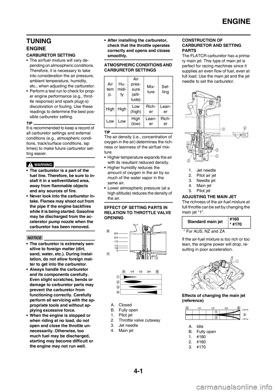
EFFECT OF SETTING PARTS IN
RELATION TO THROTTLE VALVE
OPENING
A. Closed
B. Fully open
1. Pilot jet
2. Throttle valve cutaway
3. Jet needle
4. Main jetCONSTRUCTION OF
CARBURETOR AND SETTING
PARTS
The FLATCR carburetor has a prima-
ry main jet. This type of main jet is
perfect for racing machines since it
supplies an even flow of fuel, even at
full load. Use the main jet and the jet
needle to set the carburetor.
1. Jet needle
2. Pilot air jet
3. Needle jet
4. Main jet
5. Pilot jet
ADJUSTING THE MAIN JET
The richness of the air-fuel mixture at
full throttle can be set by changing the
main jet "1".
If the air-fuel mixture is too rich or too
lean, the engine power will drop, re-
sulting in poor acceleration.
Effects of changing the main jet
(reference)
A. Idle
B. Fully open
1. #180
2. #160
3. #170 Air
tem
p.Hu-
midi-
tyAir
pres-
sure
(alti-
tude)Mix-
tureSet-
ting
High HighLow
(high)Rich-
erLean-
er
Low LowHigh
(low)Lean-
erRich-
er
Standard main jet#160
* #170
* For AUS, NZ and ZA
Page 109 of 230
5-8
CARBURETOR
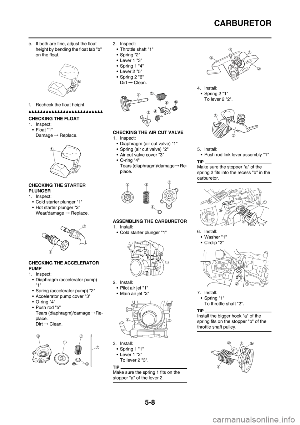
e. If both are fine, adjust the float
height by bending the float tab "b"
on the float.
f. Recheck the float height.
CHECKING THE FLOAT
1. Inspect:
• Float "1"
Damage→Replace.
CHECKING THE STARTER
PLUNGER
1. Inspect:
• Cold starter plunger "1"
• Hot starter plunger "2"
Wear/damage→Replace.
CHECKING THE ACCELERATOR
PUMP
1. Inspect:
• Diaphragm (accelerator pump)
"1"
• Spring (accelerator pump) "2"
• Accelerator pump cover "3"
• O-ring "4"
• Push rod "5"
Tears (diaphragm)/damage→Re-
place.
Dirt→Clean.2. Inspect:
• Throttle shaft "1"
• Spring "2"
• Lever 1 "3"
• Spring 1 "4"
• Lever 2 "5"
• Spring 2 "6"
Dirt→Clean.
CHECKING THE AIR CUT VALVE
1. Inspect:
• Diaphragm (air cut valve) "1"
• Spring (air cut valve) "2"
• Air cut valve cover "3"
• O-ring "4"
Tears (diaphragm)/damage→Re-
place.
ASSEMBLING THE CARBURETOR
1. Install:
• Cold starter plunger "1"
2. Install:
•Pilot air jet "1"
• Main air jet "2"
3. Install:
• Spring 1 "1"
• Lever 1 "2"
To lever 2 "3".
Make sure the spring 1 fits on the
stopper "a" of the lever 2.
4. Install:
• Spring 2 "1"
To lever 2 "2".
5. Install:
• Push rod link lever assembly "1"
Make sure the stopper "a" of the
spring 2 fits into the recess "b" in the
carburetor.
6. Install:
• Washer "1"
• Circlip "2"
7. Install:
• Spring "1"
To throttle shaft "2".
Install the bigger hook "a" of the
spring fits on the stopper "b" of the
throttle shaft pulley.
Page 110 of 230
5-9
CARBURETOR
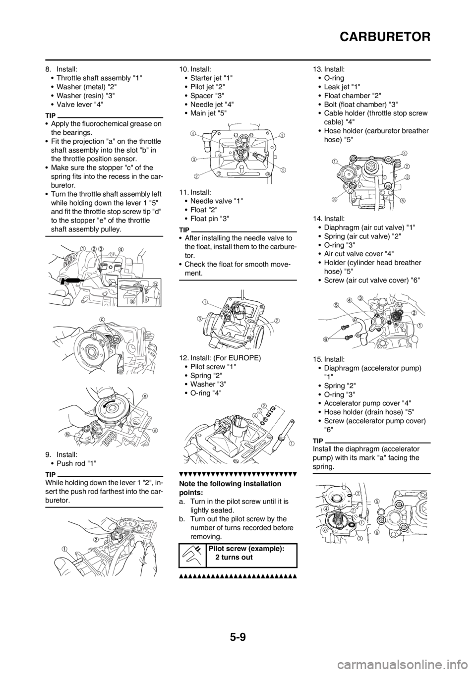
8. Install:
• Throttle shaft assembly "1"
• Washer (metal) "2"
• Washer (resin) "3"
• Valve lever "4"
• Apply the fluorochemical grease on
the bearings.
• Fit the projection "a" on the throttle
shaft assembly into the slot "b" in
the throttle position sensor.
• Make sure the stopper "c" of the
spring fits into the recess in the car-
buretor.
• Turn the throttle shaft assembly left
while holding down the lever 1 "5"
and fit the throttle stop screw tip "d"
to the stopper "e" of the throttle
shaft assembly pulley.
9. Install:
• Push rod "1"
While holding down the lever 1 "2", in-
sert the push rod farthest into the car-
buretor.
10. Install:
• Starter jet "1"
• Pilot jet "2"
• Spacer "3"
• Needle jet "4"
•Main jet "5"
11. Install:
• Needle valve "1"
•Float "2"
• Float pin "3"
• After installing the needle valve to
the float, install them to the carbure-
tor.
• Check the float for smooth move-
ment.
12. Install: (For EUROPE)
• Pilot screw "1"
• Spring "2"
• Washer "3"
• O-ring "4"
Note the following installation
points:
a. Turn in the pilot screw until it is
lightly seated.
b. Turn out the pilot screw by the
number of turns recorded before
removing.
13. Install:
• O-ring
• Leak jet "1"
• Float chamber "2"
• Bolt (float chamber) "3"
• Cable holder (throttle stop screw
cable) "4"
• Hose holder (carburetor breather
hose) "5"
14. Install:
• Diaphragm (air cut valve) "1"
• Spring (air cut valve) "2"
• O-ring "3"
• Air cut valve cover "4"
• Holder (cylinder head breather
hose) "5"
• Screw (air cut valve cover) "6"
15. Install:
• Diaphragm (accelerator pump)
"1"
• Spring "2"
• O-ring "3"
• Accelerator pump cover "4"
• Hose holder (drain hose) "5"
• Screw (accelerator pump cover)
"6"
Install the diaphragm (accelerator
pump) with its mark "a" facing the
spring.
Pilot screw (example):
2 turns out
Page 148 of 230
5-47
KICK SHAFT AND SHIFT SHAFT
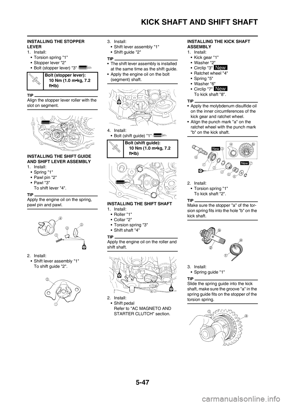
INSTALLING THE STOPPER
LEVER
1. Install:
• Torsion spring "1"
• Stopper lever "2"
• Bolt (stopper lever) "3"
Align the stopper lever roller with the
slot on segment.
INSTALLING THE SHIFT GUIDE
AND SHIFT LEVER ASSEMBLY
1. Install:
• Spring "1"
• Pawl pin "2"
•Pawl "3"
To shift lever "4".
Apply the engine oil on the spring,
pawl pin and pawl.
2. Install:
• Shift lever assembly "1"
To shift guide "2".3. Install:
• Shift lever assembly "1"
• Shift guide "2"
• The shift lever assembly is installed
at the same time as the shift guide.
• Apply the engine oil on the bolt
(segment) shaft.
4. Install:
• Bolt (shift guide) "1"
INSTALLING THE SHIFT SHAFT
1. Install:
• Roller "1"
• Collar "2"
• Torsion spring "3"
• Shift shaft "4"
Apply the engine oil on the roller and
shift shaft.
2. Install:
• Shift pedal
Refer to "AC MAGNETO AND
STARTER CLUTCH" section.INSTALLING THE KICK SHAFT
ASSEMBLY
1. Install:
• Kick gear "1"
• Washer "2"
• Circlip "3"
• Ratchet wheel "4"
• Spring "5"
• Washer "6"
• Circlip "7"
To kick shaft "8".
• Apply the molybdenum disulfide oil
on the inner circumferences of the
kick gear and ratchet wheel.
• Align the punch mark "a" on the
ratchet wheel with the punch mark
"b" on the kick shaft.
2. Install:
• Torsion spring "1"
To kick shaft "2".
Make sure the stopper "a" of the tor-
sion spring fits into the hole "b" on the
kick shaft.
3. Install:
• Spring guide "1"
Slide the spring guide into the kick
shaft, make sure the groove "a" in the
spring guide fits on the stopper of the
torsion spring.
Bolt (stopper lever):
10 Nm (1.0 m•kg, 7.2
ft•lb)
Bolt (shift guide):
10 Nm (1.0 m•kg, 7.2
ft•lb)
Page 190 of 230
6-23
HANDLEBAR
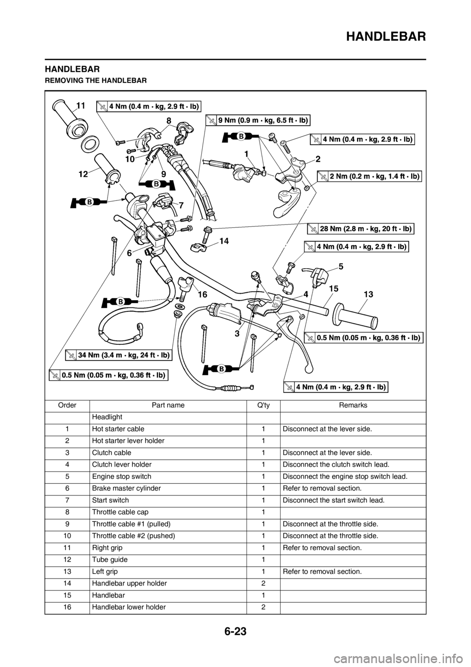
HANDLEBAR
REMOVING THE HANDLEBAR
Order Part name Q'ty Remarks
Headlight
1 Hot starter cable 1 Disconnect at the lever side.
2 Hot starter lever holder 1
3 Clutch cable 1 Disconnect at the lever side.
4 Clutch lever holder 1 Disconnect the clutch switch lead.
5 Engine stop switch 1 Disconnect the engine stop switch lead.
6 Brake master cylinder 1 Refer to removal section.
7 Start switch 1 Disconnect the start switch lead.
8 Throttle cable cap 1
9 Throttle cable #1 (pulled) 1 Disconnect at the throttle side.
10 Throttle cable #2 (pushed) 1 Disconnect at the throttle side.
11 Right grip 1 Refer to removal section.
12 Tube guide 1
13 Left grip 1 Refer to removal section.
14 Handlebar upper holder 2
15 Handlebar 1
16 Handlebar lower holder 2
Page 192 of 230
6-25
HANDLEBAR
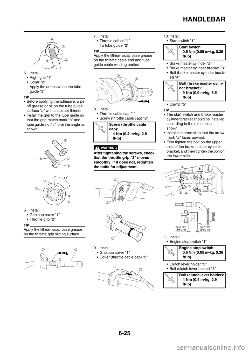
5. Install:
• Right grip "1"
•Collar "2"
Apply the adhesive on the tube
guide "3".
• Before applying the adhesive, wipe
off grease or oil on the tube guide
surface "a" with a lacquer thinner.
• Install the grip to the tube guide so
that the grip match mark "b" and
tube guide slot "c" form the angle as
shown.
6. Install:
• Grip cap cover "1"
• Throttle grip "2"
Apply the lithium soap base grease
on the throttle grip sliding surface.
7. Install:
• Throttle cables "1"
To tube guide "2".
Apply the lithium soap base grease
on the throttle cable end and tube
guide cable winding portion.
8. Install:
• Throttle cable cap "1"
• Screw (throttle cable cap) "2"
After tightening the screws, check
that the throttle grip "3" moves
smoothly. If it does not, retighten
the bolts for adjustment.
9. Install:
• Grip cap cover "1"
• Cover (throttle cable cap) "2"10. Install:
• Start switch "1"
• Brake master cylinder "2"
• Brake master cylinder bracket "3"
• Bolt (brake master cylinder brack-
et) "4"
• Clamp "5"
• The start switch and brake master
cylinder bracket should be installed
according to the dimensions
shown.
• Install the bracket so that the arrow
mark "a" faces upward.
• First tighten the bolt on the upper
side of the brake master cylinder
bracket, and then tighten the bolt on
the lower side.
11. Install:
• Engine stop switch "1"
• Clutch lever holder "2"
• Bolt (clutch lever holder) "3"
Screw (throttle cable
cap):
4 Nm (0.4 m•kg, 2.9
ft•lb)
Start switch:
0.5 Nm (0.05 m•kg, 0.36
ft•lb)
Bolt (brake master cylin-
der bracket):
9 Nm (0.9 m•kg, 6.5
ft•lb)
Engine stop switch:
0.5 Nm (0.05 m•kg, 0.36
ft•lb)
Bolt (clutch lever holder):
4 Nm (0.4 m•kg, 2.9
ft•lb)
Page 193 of 230
6-26
HANDLEBAR
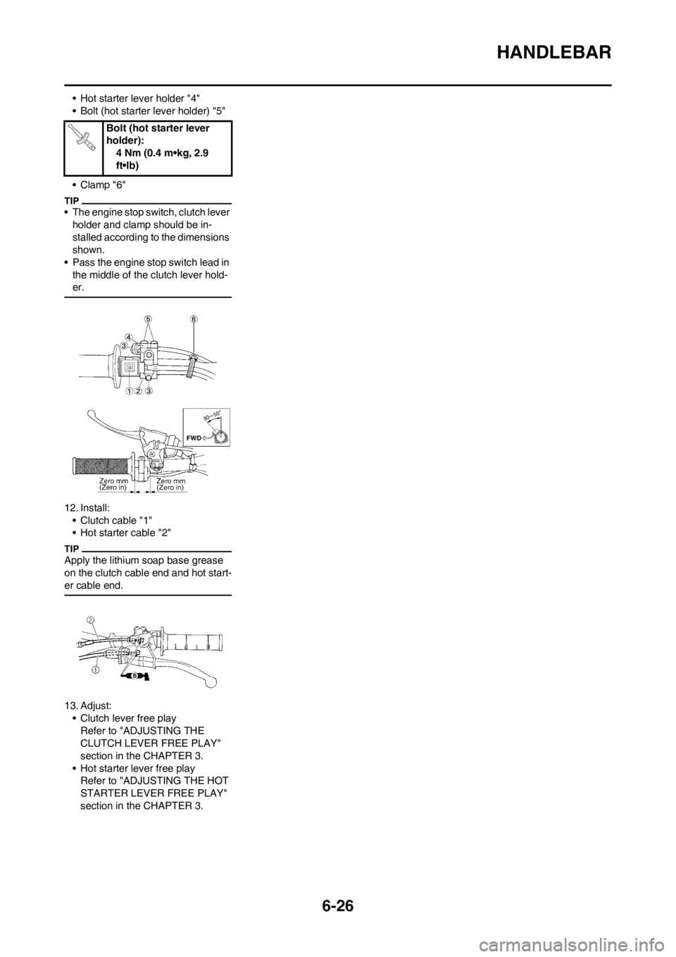
• Hot starter lever holder "4"
• Bolt (hot starter lever holder) "5"
• Clamp "6"
• The engine stop switch, clutch lever
holder and clamp should be in-
stalled according to the dimensions
shown.
• Pass the engine stop switch lead in
the middle of the clutch lever hold-
er.
12. Install:
• Clutch cable "1"
• Hot starter cable "2"
Apply the lithium soap base grease
on the clutch cable end and hot start-
er cable end.
13. Adjust:
• Clutch lever free play
Refer to "ADJUSTING THE
CLUTCH LEVER FREE PLAY"
section in the CHAPTER 3.
• Hot starter lever free play
Refer to "ADJUSTING THE HOT
STARTER LEVER FREE PLAY"
section in the CHAPTER 3.Bolt (hot starter lever
holder):
4 Nm (0.4 m•kg, 2.9
ft•lb)