stop start YAMAHA WR 250F 2014 Owner's Manual
[x] Cancel search | Manufacturer: YAMAHA, Model Year: 2014, Model line: WR 250F, Model: YAMAHA WR 250F 2014Pages: 230, PDF Size: 13.01 MB
Page 208 of 230
7-1
ELECTRICAL COMPONENTS AND WIRING DIAGRAM
ELECTRICAL
This section is intended for those who have basic knowledge and skill concerning the servicing of Yamaha motorcycles
(e.g., Yamaha dealers, service engineers, etc.) Those who have little knowledge and skill concerning servicing are request-
ed not to undertake inspection, adjustment, disassembly, or reassembly only by reference to this manual. It may lead to
servicing trouble and mechanical damage.
ELECTRICAL COMPONENTS AND WIRING DIAGRAM
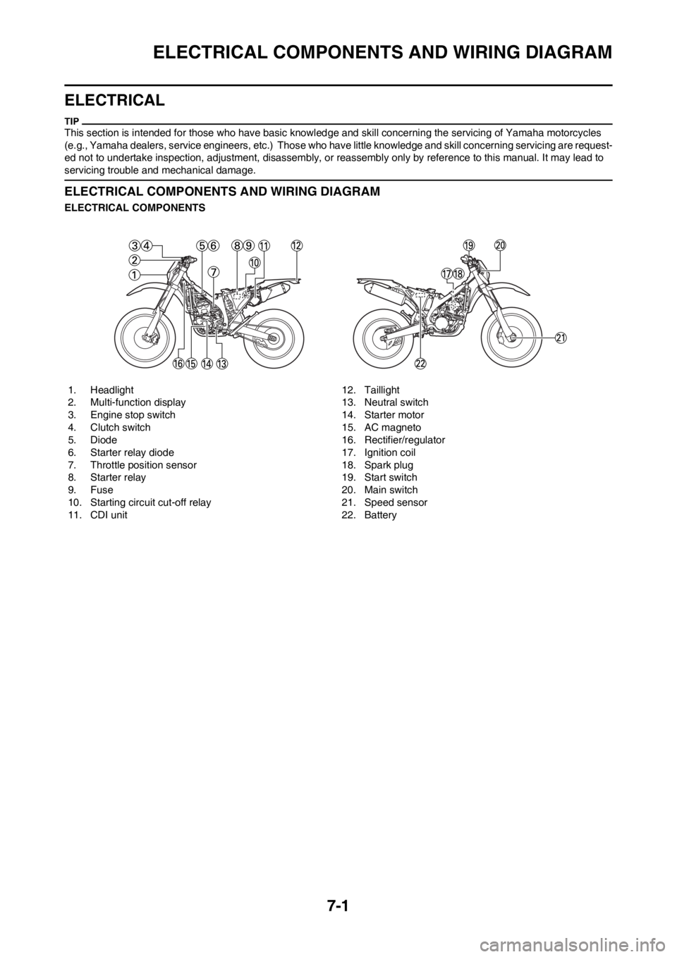
ELECTRICAL COMPONENTS
1. Headlight
2. Multi-function display
3. Engine stop switch
4. Clutch switch
5. Diode
6. Starter relay diode
7. Throttle position sensor
8. Starter relay
9. Fuse
10. Starting circuit cut-off relay
11. CDI unit12. Taillight
13. Neutral switch
14. Starter motor
15. AC magneto
16. Rectifier/regulator
17. Ignition coil
18. Spark plug
19. Start switch
20. Main switch
21. Speed sensor
22. Battery
Page 209 of 230
7-2
ELECTRICAL COMPONENTS AND WIRING DIAGRAM
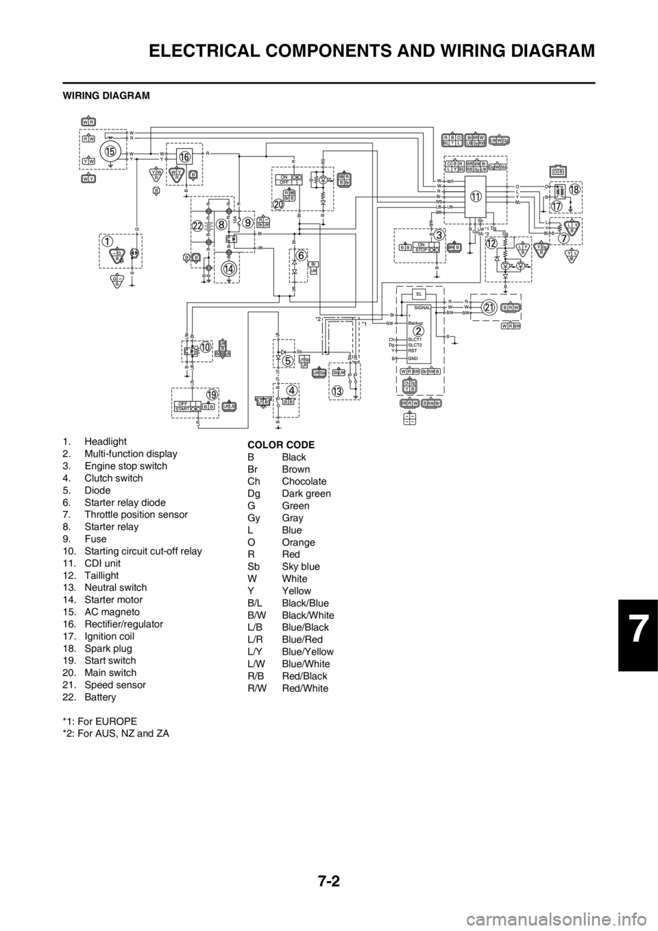
WIRING DIAGRAM
1. Headlight
2. Multi-function display
3. Engine stop switch
4. Clutch switch
5. Diode
6. Starter relay diode
7. Throttle position sensor
8. Starter relay
9. Fuse
10. Starting circuit cut-off relay
11. CDI unit
12. Taillight
13. Neutral switch
14. Starter motor
15. AC magneto
16. Rectifier/regulator
17. Ignition coil
18. Spark plug
19. Start switch
20. Main switch
21. Speed sensor
22. Battery
*1: For EUROPE
*2: For AUS, NZ and ZACOLOR CODE
BBlack
Br Brown
Ch Chocolate
Dg Dark green
GGreen
Gy Gray
LBlue
O Orange
RRed
Sb Sky blue
WWhite
YYellow
B/L Black/Blue
B/W Black/White
L/B Blue/Black
L/R Blue/Red
L/Y Blue/Yellow
L/W Blue/White
R/B Red/Black
R/W Red/White
7
Page 211 of 230
7-4
IGNITION SYSTEM
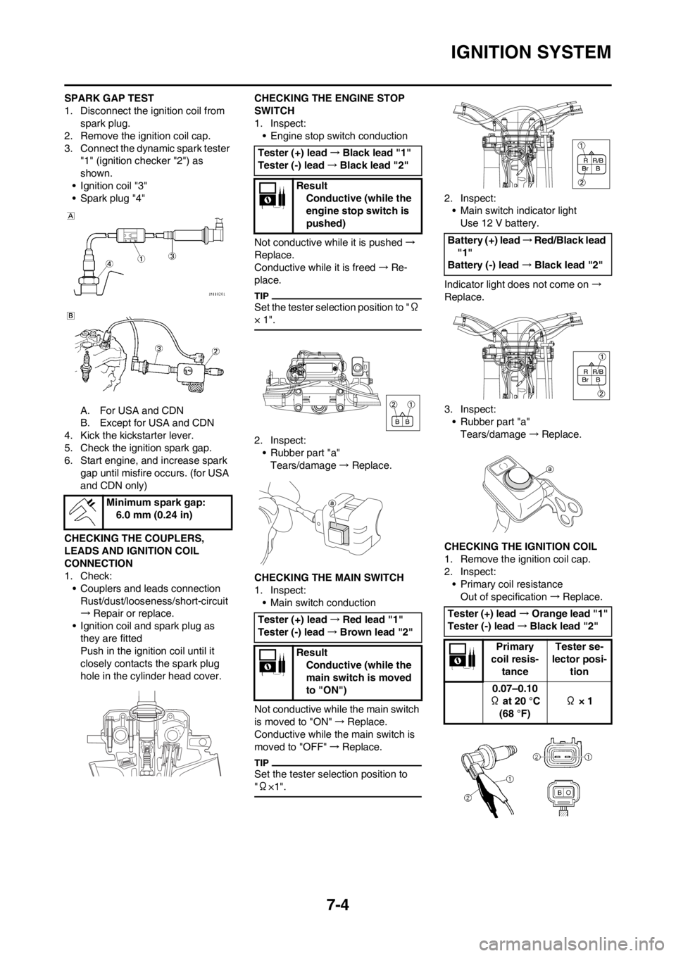
SPARK GAP TEST
1. Disconnect the ignition coil from
spark plug.
2. Remove the ignition coil cap.
3. Connect the dynamic spark tester
"1" (ignition checker "2") as
shown.
• Ignition coil "3"
• Spark plug "4"
A. For USA and CDN
B. Except for USA and CDN
4. Kick the kickstarter lever.
5. Check the ignition spark gap.
6. Start engine, and increase spark
gap until misfire occurs. (for USA
and CDN only)
CHECKING THE COUPLERS,
LEADS AND IGNITION COIL
CONNECTION
1. Check:
• Couplers and leads connection
Rust/dust/looseness/short-circuit
→Repair or replace.
• Ignition coil and spark plug as
they are fitted
Push in the ignition coil until it
closely contacts the spark plug
hole in the cylinder head cover.CHECKING THE ENGINE STOP
SWITCH
1. Inspect:
• Engine stop switch conduction
Not conductive while it is pushed→
Replace.
Conductive while it is freed→Re-
place.
Set the tester selection position to "Ω
× 1".
2. Inspect:
• Rubber part "a"
Tears/damage→ Replace.
CHECKING THE MAIN SWITCH
1. Inspect:
• Main switch conduction
Not conductive while the main switch
is moved to "ON"→Replace.
Conductive while the main switch is
moved to "OFF"→Replace.
Set the tester selection position to
"Ω×1".
2. Inspect:
• Main switch indicator light
Use 12 V battery.
Indicator light does not come on→
Replace.
3. Inspect:
• Rubber part "a"
Tears/damage→Replace.
CHECKING THE IGNITION COIL
1. Remove the ignition coil cap.
2. Inspect:
• Primary coil resistance
Out of specification→Replace. Minimum spark gap:
6.0 mm (0.24 in)
Tester (+) lead→Black lead "1"
Tester (-) lead→Black lead "2"
Result
Conductive (while the
engine stop switch is
pushed)
Tester (+) lead→Red lead "1"
Tester (-) lead→Brown lead "2"
Result
Conductive (while the
main switch is moved
to "ON")
Battery (+) lead→Red/Black lead
"1"
Battery (-) lead→Black lead "2"
Tester (+) lead→Orange lead "1"
Tester (-) lead→Black lead "2"
Primary
coil resis-
tanceTester se-
lector posi-
tion
0.07–0.10
Ω at 20 °C
(68 °F) Ω × 1
Page 223 of 230
7-16
THROTTLE POSITION SENSOR SYSTEM
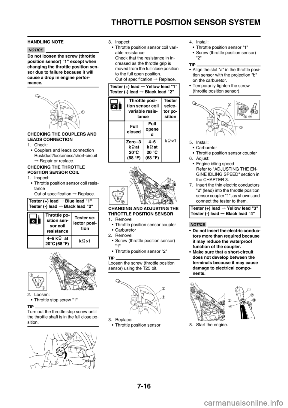
HANDLING NOTE
Do not loosen the screw (throttle
position sensor) "1" except when
changing the throttle position sen-
sor due to failure because it will
cause a drop in engine perfor-
mance.
CHECKING THE COUPLERS AND
LEADS CONNECTION
1. Check:
• Couplers and leads connection
Rust/dust/looseness/short-circuit
→Repair or replace.
CHECKING THE THROTTLE
POSITION SENSOR COIL
1. Inspect:
• Throttle position sensor coil resis-
tance
Out of specification→Replace.
2. Loosen:
• Throttle stop screw "1"
Turn out the throttle stop screw until
the throttle shaft is in the full close po-
sition.
3. Inspect:
• Throttle position sensor coil vari-
able resistance
Check that the resistance in in-
creased as the throttle grip is
moved from the full close position
to the full open position.
Out of specification→Replace.
CHANGING AND ADJUSTING THE
THROTTLE POSITION SENSOR
1. Remove:
• Throttle position sensor coupler
• Carburetor
2. Remove:
• Screw (throttle position sensor)
"1"
• Throttle position sensor "2"
Loosen the screw (throttle position
sensor) using the T25 bit.
3. Replace:
• Throttle position sensor4. Install:
• Throttle position sensor "1"
• Screw (throttle position sensor)
"2"
• Align the slot "a" in the throttle posi-
tion sensor with the projection "b"
on the carburetor.
• Temporarily tighten the screw
(throttle position sensor).
5. Install:
•Carburetor
• Throttle position sensor coupler
6. Adjust:
• Engine idling speed
Refer to "ADJUSTING THE EN-
GINE IDLING SPEED" section in
the CHAPTER 3.
7. Insert the thin electric conductors
"2" (lead) into the throttle position
sensor coupler "1", as shown, and
connect the tester to them.
• Do not insert the electric conduc-
tors more than required because
it may reduce the waterproof
function of the coupler.
• Make sure that a short-circuit
does not develop between the
terminals because it may cause
damage to electrical compo-
nents.
8. Start the engine. Tester (+) lead→Blue lead "1"
Tester (-) lead→Black lead "2"
Throttle po-
sition sen-
sor coil
resistanceTester se-
lector posi-
tion
4–6 kΩ at
20°C (68 °F) kΩ×1
Tester (+) lead→Yellow lead "1"
Tester (-) lead→Black lead "2"
Throttle posi-
tion sensor coil
variable resis-
tanceTester
selec-
tor po-
sition
Full
closedFull
opene
d
kΩ×1
Zero –3
kΩat
20°C
(68 °F)4–6
kΩat
20 °C
(68 °F)
Tester (+) lead→Yellow lead "3"
Tester (-) lead→Black lead "4"
Page 224 of 230
7-17
THROTTLE POSITION SENSOR SYSTEM
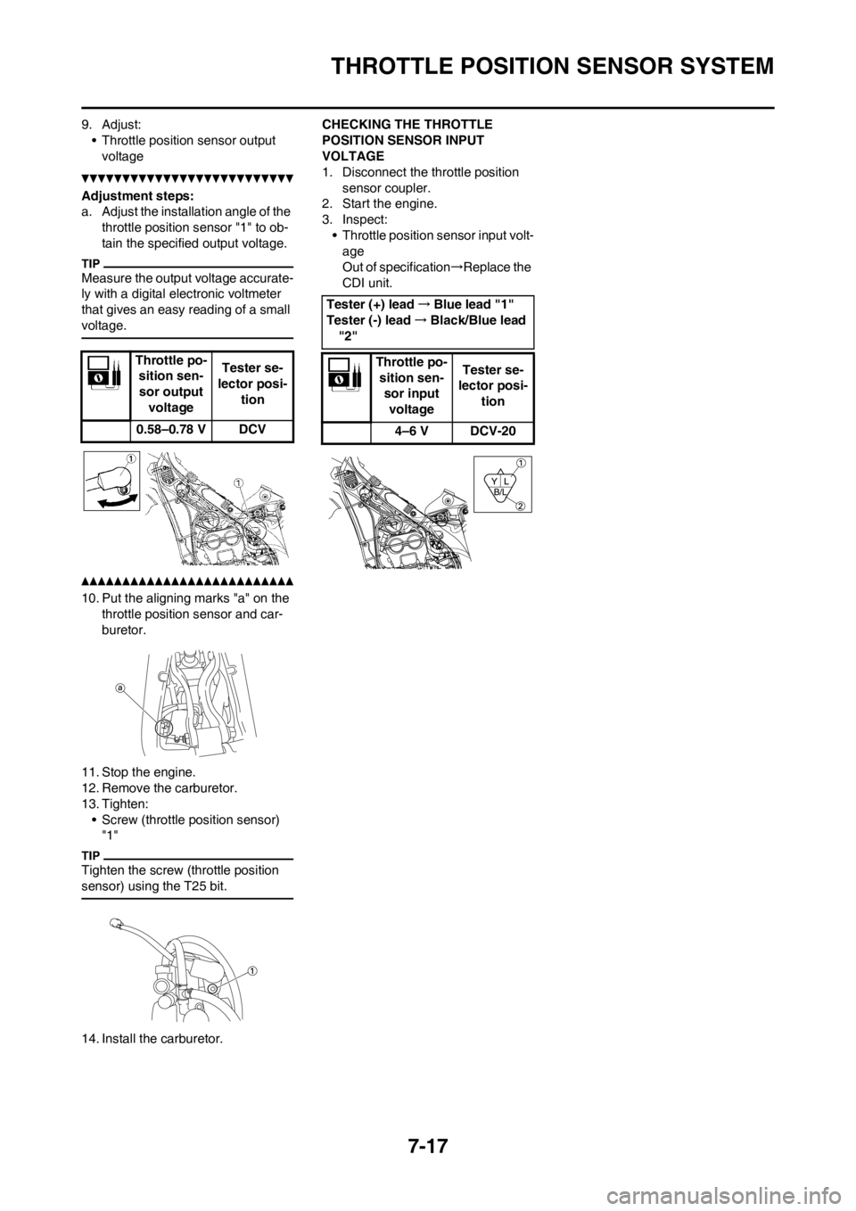
9. Adjust:
• Throttle position sensor output
voltage
Adjustment steps:
a. Adjust the installation angle of the
throttle position sensor "1" to ob-
tain the specified output voltage.
Measure the output voltage accurate-
ly with a digital electronic voltmeter
that gives an easy reading of a small
voltage.
10. Put the aligning marks "a" on the
throttle position sensor and car-
buretor.
11. Stop the engine.
12. Remove the carburetor.
13. Tighten:
• Screw (throttle position sensor)
"1"
Tighten the screw (throttle position
sensor) using the T25 bit.
14. Install the carburetor.CHECKING THE THROTTLE
POSITION SENSOR INPUT
VOLTAGE
1. Disconnect the throttle position
sensor coupler.
2. Start the engine.
3. Inspect:
• Throttle position sensor input volt-
age
Out of specification→Replace the
CDI unit.
Throttle po-
sition sen-
sor output
voltageTester se-
lector posi-
tion
0.58–0.78 V DCV
Tester (+) lead→Blue lead "1"
Tester (-) lead→Black/Blue lead
"2"
Throttle po-
sition sen-
sor input
voltage Tester se-
lector posi-
tion
4–6 V DCV-20