YAMAHA WR 250F 2014 Workshop Manual
Manufacturer: YAMAHA, Model Year: 2014, Model line: WR 250F, Model: YAMAHA WR 250F 2014Pages: 230, PDF Size: 13.01 MB
Page 51 of 230
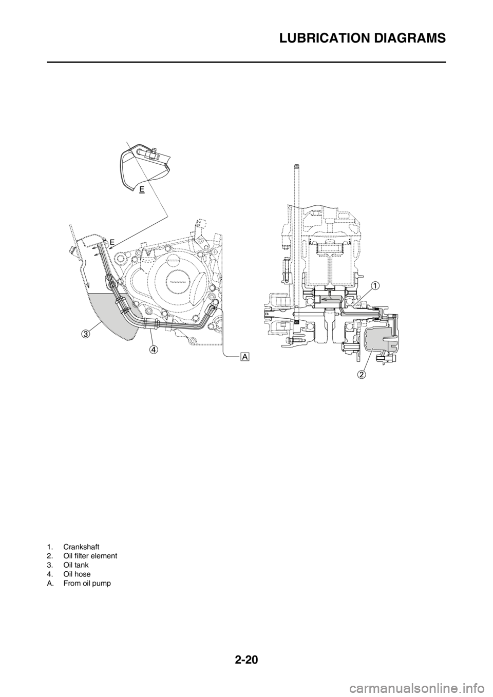
2-20
LUBRICATION DIAGRAMS
1. Crankshaft
2. Oil filter element
3. Oil tank
4. Oil hose
A. From oil pump
Page 52 of 230
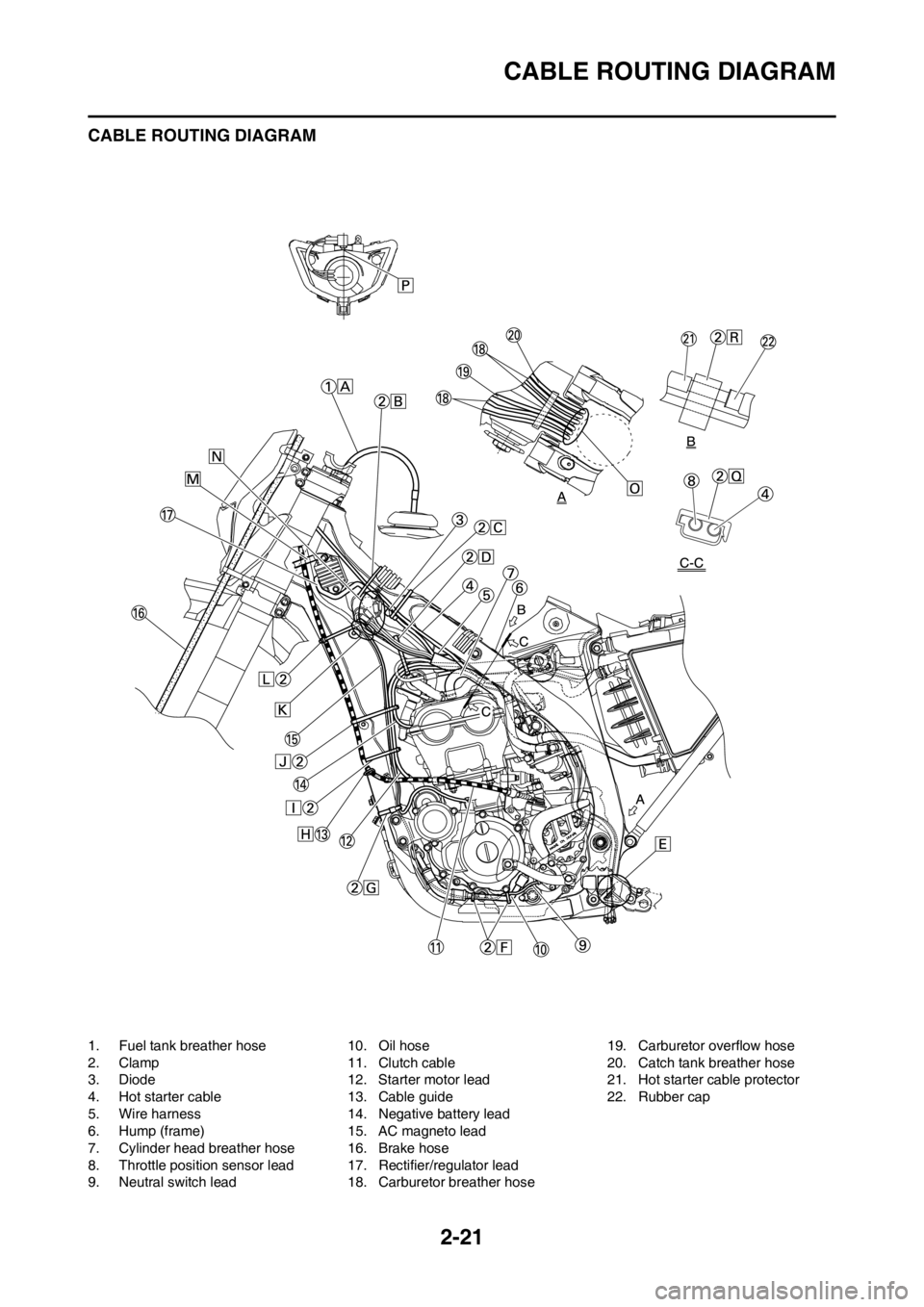
2-21
CABLE ROUTING DIAGRAM
CABLE ROUTING DIAGRAM
1. Fuel tank breather hose
2. Clamp
3. Diode
4. Hot starter cable
5. Wire harness
6. Hump (frame)
7. Cylinder head breather hose
8. Throttle position sensor lead
9. Neutral switch lead10. Oil hose
11. Clutch cable
12. Starter motor lead
13. Cable guide
14. Negative battery lead
15. AC magneto lead
16. Brake hose
17. Rectifier/regulator lead
18. Carburetor breather hose19. Carburetor overflow hose
20. Catch tank breather hose
21. Hot starter cable protector
22. Rubber cap
Page 53 of 230

2-22
CABLE ROUTING DIAGRAM
A. Insert the end of the fuel tank
breather hose into the hole in
the steering stem.
B. Fasten the throttle cable, hot
starter cable and rectifier/regula-
tor lead onto the frame. Locate
the clamp under the throttle ca-
ble on the right side of the frame,
and face its ends, as well as the
tie ends, downward.
C. Fasten the diode (at the mark-
ing), throttle cable and hot start-
er cable onto the frame. Locate
the clamp end facing toward the
lower right of the frame and with
the tie end facing downward.
D. Fasten the wire harness, throttle
position sensor lead, starter mo-
tor lead and negative battery
lead onto the frame. Pass the
clamp through the hole in the
stay (air cut-off valve). Locate
the clamp end facing toward the
lower side of the frame and cut
off the tie end.
E. Pass the carburetor breather
hoses, carburetor overflow hose
and catch tank breather hose
between the connecting rod and
cross tube (frame).
F. Fasten the neutral switch lead
and oil hose together with the
plastic locking ties and cut off
the tie ends.
G. Fasten the neutral switch lead
and AC magneto lead onto the
frame. Locate the clamp end
facing toward the outside of the
frame and tie end facing toward
the rear of the frame.
H. Pass the clutch cable through
the cable guide.
I. Fasten the starter motor lead,
AC magneto lead and neutral
switch lead onto the frame. Lo-
cate the clamp end facing to-
ward the rear of the frame and
cut off the tie end.
J. Fasten the clutch cable, starter
motor lead, negative battery
lead, AC magneto lead and neu-
tral switch lead onto the frame.
Locate the clamp end facing to-
ward the rear of the frame and
cut off the tie end.
K. Pass the neutral switch lead and
AC magneto lead on the inside
of the wire harness.
L. Fasten the clutch cable, AC
magneto lead and neutral switch
lead onto the frame. Locate the
clamp end near the clutch cable
and cut off the tie end.M. Pass the clutch cable and wire
harness through the cable
guide.
N. Locate the couplers in the frame
recess.
O. Pass the carburetor breather
hoses, carburetor overflow hose
and catch tank breather hose so
that the hoses do not contact the
rear shock absorber.
P. Secure the coupler by pushing it
into the hole in the headlight
unit.
Q. Fasten the throttle position sen-
sor lead and the hot starter ca-
ble.
R. Locate the clamp between the
hot starter cable protector and
rubber cap.
Page 54 of 230
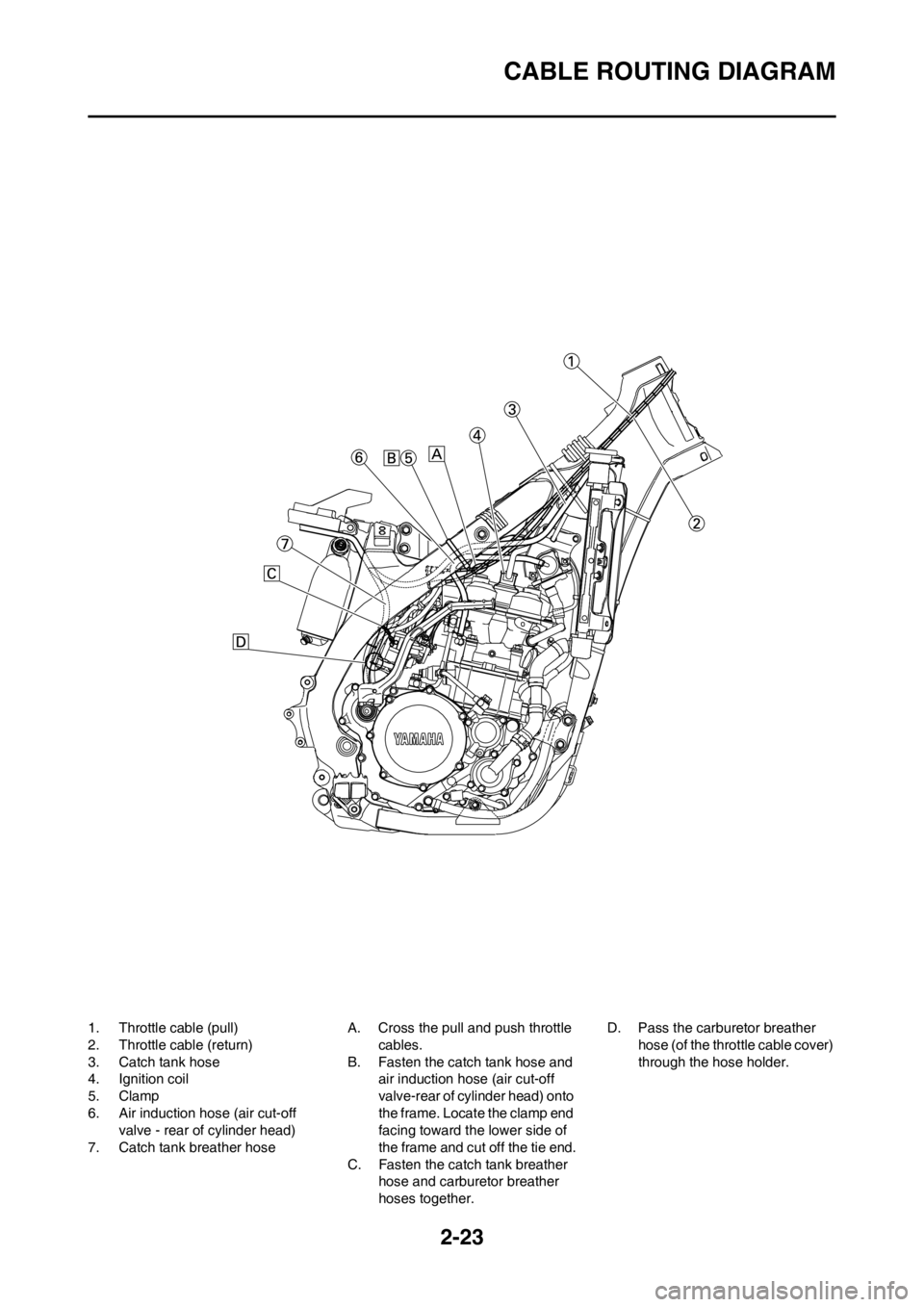
2-23
CABLE ROUTING DIAGRAM
1. Throttle cable (pull)
2. Throttle cable (return)
3. Catch tank hose
4. Ignition coil
5. Clamp
6. Air induction hose (air cut-off
valve - rear of cylinder head)
7. Catch tank breather hoseA. Cross the pull and push throttle
cables.
B. Fasten the catch tank hose and
air induction hose (air cut-off
valve-rear of cylinder head) onto
the frame. Locate the clamp end
facing toward the lower side of
the frame and cut off the tie end.
C. Fasten the catch tank breather
hose and carburetor breather
hoses together.D. Pass the carburetor breather
hose (of the throttle cable cover)
through the hose holder.
Page 55 of 230
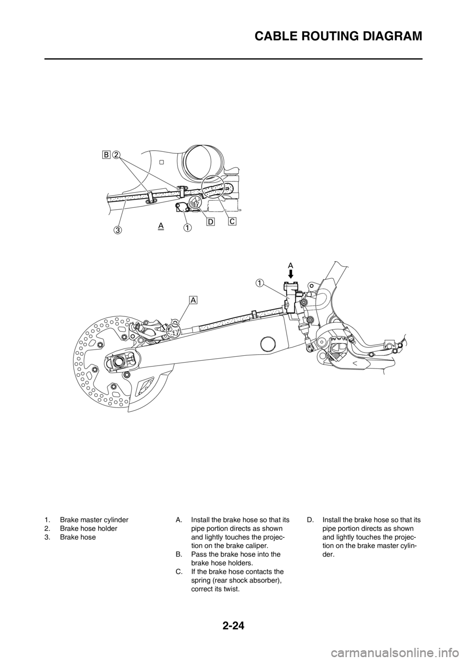
2-24
CABLE ROUTING DIAGRAM
1. Brake master cylinder
2. Brake hose holder
3. Brake hoseA. Install the brake hose so that its
pipe portion directs as shown
and lightly touches the projec-
tion on the brake caliper.
B. Pass the brake hose into the
brake hose holders.
C. If the brake hose contacts the
spring (rear shock absorber),
correct its twist.D. Install the brake hose so that its
pipe portion directs as shown
and lightly touches the projec-
tion on the brake master cylin-
der.
Page 56 of 230
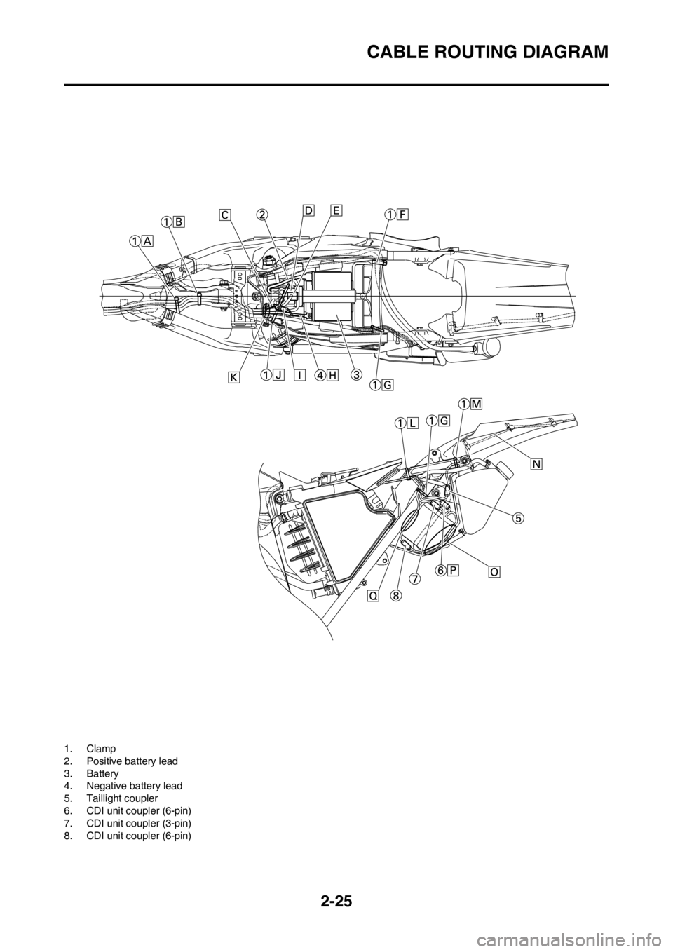
2-25
CABLE ROUTING DIAGRAM
1. Clamp
2. Positive battery lead
3. Battery
4. Negative battery lead
5. Taillight coupler
6. CDI unit coupler (6-pin)
7. CDI unit coupler (3-pin)
8. CDI unit coupler (6-pin)
Page 57 of 230

2-26
CABLE ROUTING DIAGRAM
A. Fasten the wire harness, nega-
tive battery lead and starter mo-
tor lead to the upper engine
bracket (left side). Locate the
clamp end facing toward the up-
per side of the frame with the tie
end cut off on the inside of the
frame.
B. Fasten the wire harness, nega-
tive battery lead and starter mo-
tor lead to the upper engine
bracket (left side). Locate the
clamp end facing toward the up-
per side of the frame with the tie
end cut off on the inside of the
frame. Clamp the wire harness
and negative lead at the mark-
ing.
C. Pass the starter motor lead
through the hole in the relay
holder.
D. Fit the cover securely.
E. Connect the wire harness to the
starter relay.
F. Fasten the catch tank breather
hose and catch tank hose to the
rear frame. Clamp them close to
where they are joined to the
frame. Fasten the pipe tightly
enough not to crush it. Locate
the clamp end facing toward the
rear of the frame with the tie end
facing downward.
G. Fasten the (three) CDI unit leads
and taillight lead to the rear
frame. Locate the clamp end
facing toward the upper side of
the frame and cut off the tie end.
H. Connect the negative battery
lead to the battery negative ter-
minal.
I. Connect the negative battery
lead to the wire harness.
J. Fasten the wire harness to the
rear frame. Locate the clamp
end facing toward the upper side
of the frame and the tie end to-
ward the inside of the frame.
Clamp the wire harness at the
marking.
K. Pass the wire harness, starter
relay lead, starting circuit cut-off
relay lead and negative battery
lead through the hole in the relay
holder.
L. Fasten the (three) CDI unit leads
and taillight lead to the rear
frame. Locate the clamp end
facing toward the lower side of
the frame and cut off the tie end.M. Fasten the taillight lead to the
rear frame. Locate the clamp
end facing toward the upper side
of the frame and cut off the tie
end.
N. Do not allow the taillight lead to
slacken.
O. Locate the CDI unit lead be-
tween the CDI unit and rear
fender.
P. Locate the CDI unit coupler in
the clearance between the up-
per side of the CDI unit and low-
er side of the catch tank stay.
Q. Locate the CDI unit lead be-
tween the CDI unit and rear
frame.
Page 58 of 230
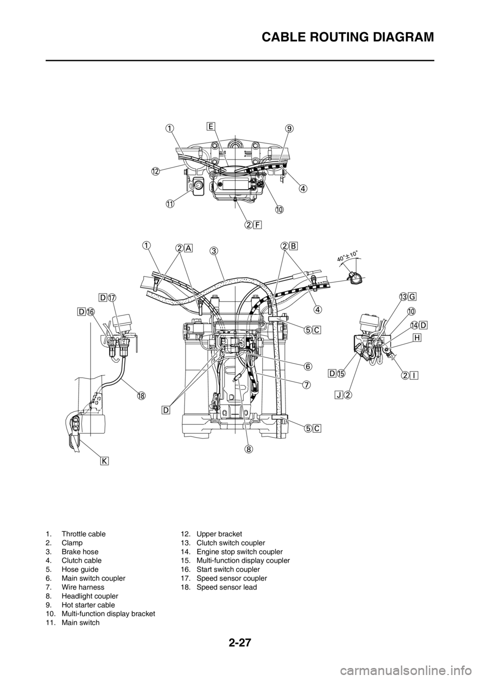
2-27
CABLE ROUTING DIAGRAM
1. Throttle cable
2. Clamp
3. Brake hose
4. Clutch cable
5. Hose guide
6. Main switch coupler
7. Wire harness
8. Headlight coupler
9. Hot starter cable
10. Multi-function display bracket
11. Main switch12. Upper bracket
13. Clutch switch coupler
14. Engine stop switch coupler
15. Multi-function display coupler
16. Start switch coupler
17. Speed sensor coupler
18. Speed sensor lead
Page 59 of 230

2-28
CABLE ROUTING DIAGRAM
A. Fasten the start switch lead to
the handlebar with the plastic
bands.
B. Fasten the engine stop switch
lead and clutch switch lead to
the handlebar with the plastic
bands.
C. Pass the brake hose through
the hose guides.
D. Secure the coupler by inserting
it into the multi-function display
bracket.
E. Pass the throttle cables, clutch
cable and hot starter cable be-
tween the upper bracket and
multi-function display bracket.
F. Fasten the multi-function display
leads to the bracket. Cut off the
tie end.
G. Secure the coupler by pushing it
into the hole in the multi-function
display bracket.
H. Secure the wire harness clip by
pushing it into the hole in the
multi-function display bracket on
the inside.
I. Fasten the wire harness to the
multi-function display bracket.
Cut off the tie end.
J. Fasten the main switch lead
(wire harness side) to the multi-
function display bracket. Locate
the clamp end facing toward the
lower side of the frame and cut
off the tie end.
K. Pass the speed sensor lead
through the guide on the outside
of the front fork.
Page 60 of 230

3-1
MAINTENANCE INTERVALS FOR COMPETITION USE
REGULAR INSPECTION AND ADJUSTMENTS
MAINTENANCE INTERVALS FOR COMPETITION USE
• The following schedule is intended as a general guide to maintenance and lubrication. Bear in mind that such factors as
weather, terrain, geographical location, and individual usage will alter the required maintenance and lubrication intervals.
If you are a doubt as to what intervals to follow in maintaining and lubricating your machine, consult your Yamaha dealer.
• Periodic inspection is essential in making full use of the machine performance. The service life of the parts varies sub-
stantially according to the environment in which the machine runs (e.g., rain, dirt, etc.). Therefore, earlier inspection is
required by reference to the list below.
ItemAfter
break-
inEvery
race
Every
third
(or 500
km)Every
fifth (or
1,000
km)
As re-
quiredRemarks
ENGINE OIL
Replace●●
VALVES
Check the valve clearances●●The engine must be cold.
Inspect●Check the valve seats and valve
stems for wear.
Replace●
VALVE SPRINGS
Inspect●Check the free length and the tilt.
Replace●
VALVE LIFTERS
Inspect●Check for scratches and wear.
Replace●
CAMSHAFTS Inspect the camshaft surface.
Inspect●Inspect the decompression system.
Replace●
CAMSHAFT SPROCKETS
Inspect●Check for wear on the teeth and for
damage.
Replace●
PISTON
Inspect●●Inspect crack.
Clean●Inspect carbon deposits and eliminate
them.
Replace●It is recommended that the piston pin
and ring are also replaced at the same
time.
PISTON RING
Inspect●Check ring end gap.
Replace●●
PISTON PIN
Inspect●
Replace●
CYLINDER HEAD Inspect carbon deposits and eliminate
them.
Inspect and clean●Change gasket.