ECU YAMAHA WR 250F 2014 Owners Manual
[x] Cancel search | Manufacturer: YAMAHA, Model Year: 2014, Model line: WR 250F, Model: YAMAHA WR 250F 2014Pages: 230, PDF Size: 13.01 MB
Page 6 of 230
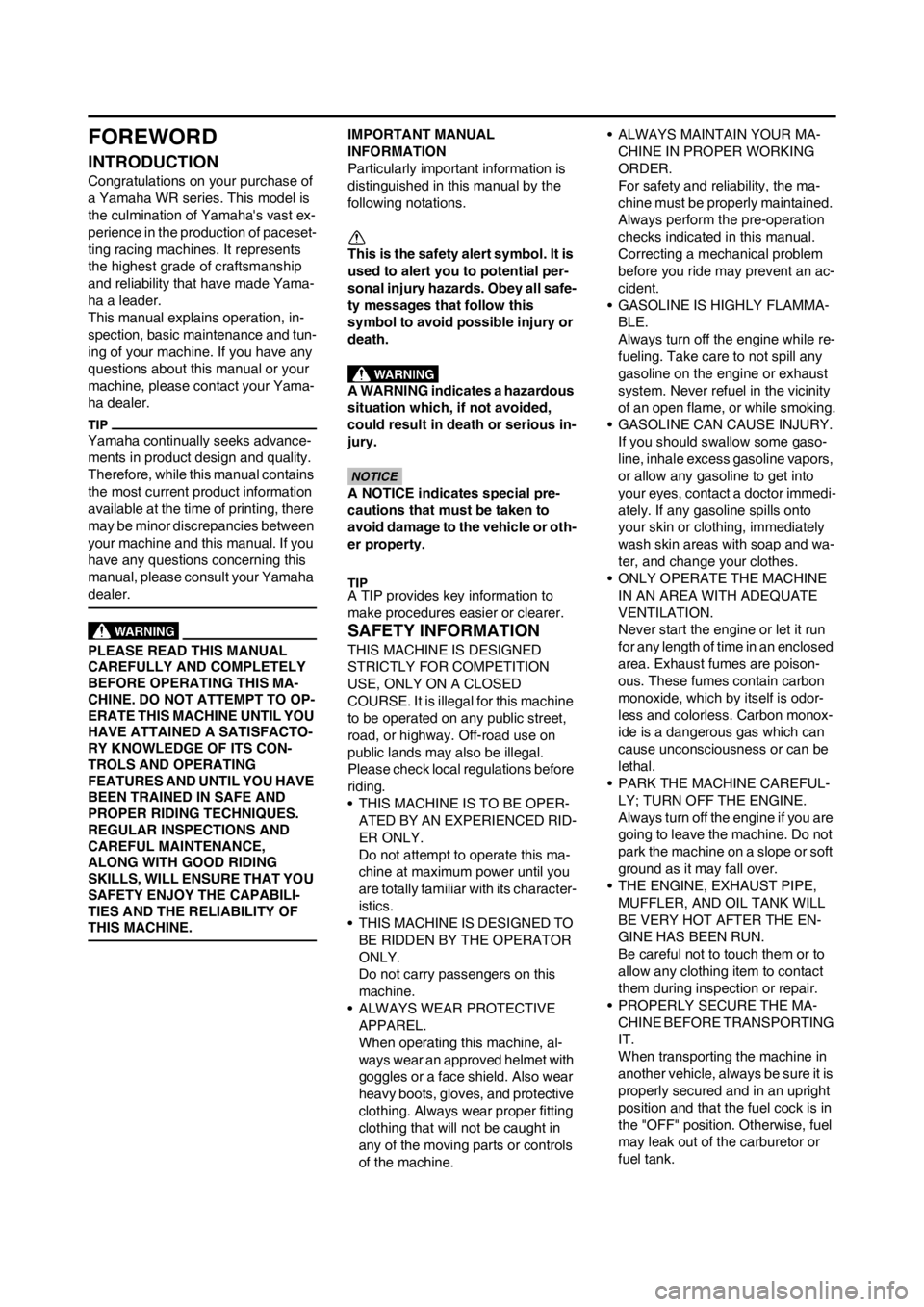
FOREWORD
INTRODUCTION
Congratulations on your purchase of
a Yamaha WR series. This model is
the culmination of Yamaha's vast ex-
perience in the production of paceset-
ting racing machines. It represents
the highest grade of craftsmanship
and reliability that have made Yama-
ha a leader.
This manual explains operation, in-
spection, basic maintenance and tun-
ing of your machine. If you have any
questions about this manual or your
machine, please contact your Yama-
ha dealer.
Yamaha continually seeks advance-
ments in product design and quality.
Therefore, while this manual contains
the most current product information
available at the time of printing, there
may be minor discrepancies between
your machine and this manual. If you
have any questions concerning this
manual, please consult your Yamaha
dealer.
PLEASE READ THIS MANUAL
CAREFULLY AND COMPLETELY
BEFORE OPERATING THIS MA-
CHINE. DO NOT ATTEMPT TO OP-
ERATE THIS MACHINE UNTIL YOU
HAVE ATTAINED A SATISFACTO-
RY KNOWLEDGE OF ITS CON-
TROLS AND OPERATING
FEATURES AND UNTIL YOU HAVE
BEEN TRAINED IN SAFE AND
PROPER RIDING TECHNIQUES.
REGULAR INSPECTIONS AND
CAREFUL MAINTENANCE,
ALONG WITH GOOD RIDING
SKILLS, WILL ENSURE THAT YOU
SAFETY ENJOY THE CAPABILI-
TIES AND THE RELIABILITY OF
THIS MACHINE.
IMPORTANT MANUAL
INFORMATION
Particularly important information is
distinguished in this manual by the
following notations.
This is the safety alert symbol. It is
used to alert you to potential per-
sonal injury hazards. Obey all safe-
ty messages that follow this
symbol to avoid possible injury or
death.
A WARNING indicates a hazardous
situation which, if not avoided,
could result in death or serious in-
jury.
A NOTICE indicates special pre-
cautions that must be taken to
avoid damage to the vehicle or oth-
er property.
A TIP provides key information to
make procedures easier or clearer.
SAFETY INFORMATION
THIS MACHINE IS DESIGNED
STRICTLY FOR COMPETITION
USE, ONLY ON A CLOSED
COURSE. It is illegal for this machine
to be operated on any public street,
road, or highway. Off-road use on
public lands may also be illegal.
Please check local regulations before
riding.
• THIS MACHINE IS TO BE OPER-
ATED BY AN EXPERIENCED RID-
ER ONLY.
Do not attempt to operate this ma-
chine at maximum power until you
are totally familiar with its character-
istics.
• THIS MACHINE IS DESIGNED TO
BE RIDDEN BY THE OPERATOR
ONLY.
Do not carry passengers on this
machine.
• ALWAYS WEAR PROTECTIVE
APPAREL.
When operating this machine, al-
ways wear an approved helmet with
goggles or a face shield. Also wear
heavy boots, gloves, and protective
clothing. Always wear proper fitting
clothing that will not be caught in
any of the moving parts or controls
of the machine.• ALWAYS MAINTAIN YOUR MA-
CHINE IN PROPER WORKING
ORDER.
For safety and reliability, the ma-
chine must be properly maintained.
Always perform the pre-operation
checks indicated in this manual.
Correcting a mechanical problem
before you ride may prevent an ac-
cident.
• GASOLINE IS HIGHLY FLAMMA-
BLE.
Always turn off the engine while re-
fueling. Take care to not spill any
gasoline on the engine or exhaust
system. Never refuel in the vicinity
of an open flame, or while smoking.
• GASOLINE CAN CAUSE INJURY.
If you should swallow some gaso-
line, inhale excess gasoline vapors,
or allow any gasoline to get into
your eyes, contact a doctor immedi-
ately. If any gasoline spills onto
your skin or clothing, immediately
wash skin areas with soap and wa-
ter, and change your clothes.
• ONLY OPERATE THE MACHINE
IN AN AREA WITH ADEQUATE
VENTILATION.
Never start the engine or let it run
for any length of time in an enclosed
area. Exhaust fumes are poison-
ous. These fumes contain carbon
monoxide, which by itself is odor-
less and colorless. Carbon monox-
ide is a dangerous gas which can
cause unconsciousness or can be
lethal.
• PARK THE MACHINE CAREFUL-
LY; TURN OFF THE ENGINE.
Always turn off the engine if you are
going to leave the machine. Do not
park the machine on a slope or soft
ground as it may fall over.
• THE ENGINE, EXHAUST PIPE,
MUFFLER, AND OIL TANK WILL
BE VERY HOT AFTER THE EN-
GINE HAS BEEN RUN.
Be careful not to touch them or to
allow any clothing item to contact
them during inspection or repair.
• PROPERLY SECURE THE MA-
CHINE BEFORE TRANSPORTING
IT.
When transporting the machine in
another vehicle, always be sure it is
properly secured and in an upright
position and that the fuel cock is in
the "OFF" position. Otherwise, fuel
may leak out of the carburetor or
fuel tank.
Page 18 of 230
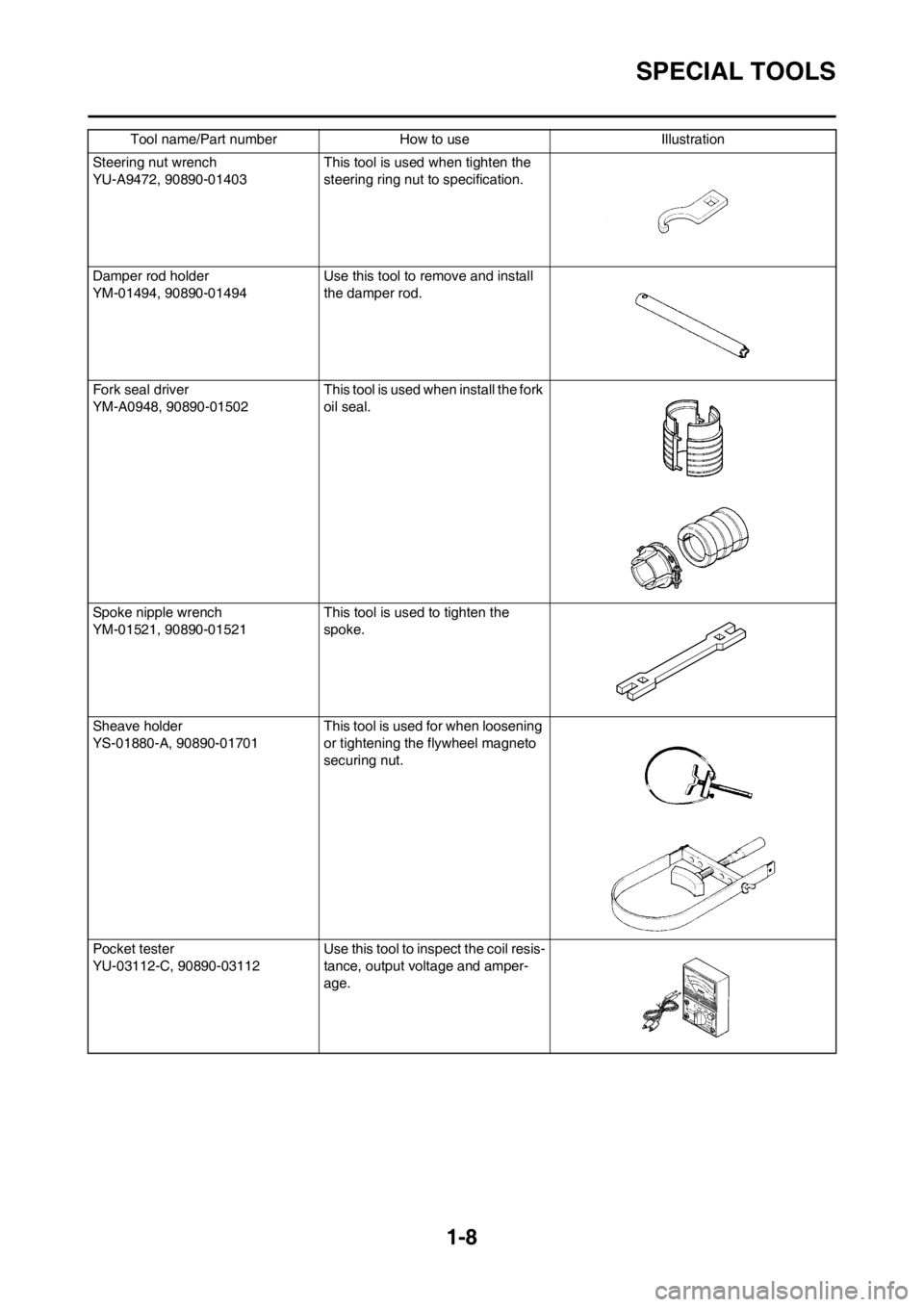
1-8
SPECIAL TOOLS
Steering nut wrench
YU-A9472, 90890-01403 This tool is used when tighten the
steering ring nut to specification.
Damper rod holder
YM-01494, 90890-01494Use this tool to remove and install
the damper rod.
Fork seal driver
YM-A0948, 90890-01502 This tool is used when install the fork
oil seal.
Spoke nipple wrench
YM-01521, 90890-01521This tool is used to tighten the
spoke.
Sheave holder
YS-01880-A, 90890-01701This tool is used for when loosening
or tightening the flywheel magneto
securing nut.
Pocket tester
YU-03112-C, 90890-03112 Use this tool to inspect the coil resis-
tance, output voltage and amper-
age. Tool name/Part number How to use Illustration
Page 19 of 230
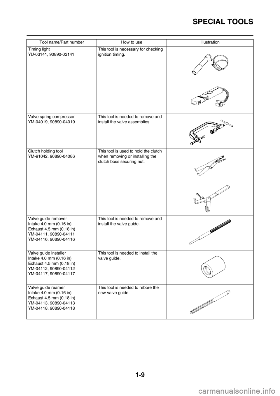
1-9
SPECIAL TOOLS
Timing light
YU-03141, 90890-03141 This tool is necessary for checking
ignition timing.
Valve spring compressor
YM-04019, 90890-04019 This tool is needed to remove and
install the valve assemblies.
Clutch holding tool
YM-91042, 90890-04086This tool is used to hold the clutch
when removing or installing the
clutch boss securing nut.
Valve guide remover
Intake 4.0 mm (0.16 in)
Exhaust 4.5 mm (0.18 in)
YM-04111, 90890-04111
YM-04116, 90890-04116This tool is needed to remove and
install the valve guide.
Valve guide installer
Intake 4.0 mm (0.16 in)
Exhaust 4.5 mm (0.18 in)
YM-04112, 90890-04112
YM-04117, 90890-04117This tool is needed to install the
valve guide.
Valve guide reamer
Intake 4.0 mm (0.16 in)
Exhaust 4.5 mm (0.18 in)
YM-04113, 90890-04113
YM-04118, 90890-04118This tool is needed to rebore the
new valve guide. Tool name/Part number How to use Illustration
Page 31 of 230
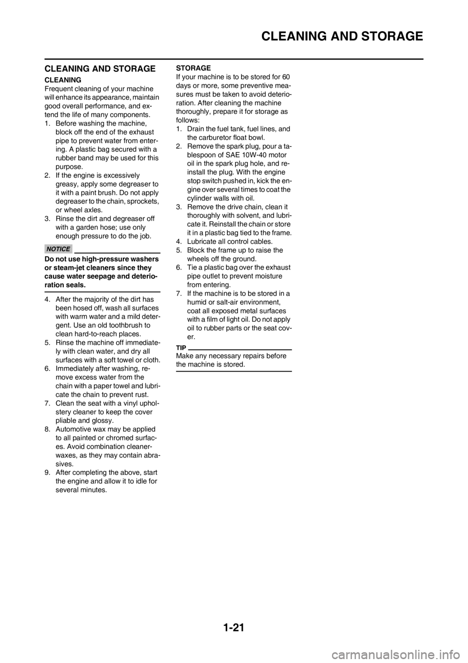
1-21
CLEANING AND STORAGE
CLEANING AND STORAGE
CLEANING
Frequent cleaning of your machine
will enhance its appearance, maintain
good overall performance, and ex-
tend the life of many components.
1. Before washing the machine,
block off the end of the exhaust
pipe to prevent water from enter-
ing. A plastic bag secured with a
rubber band may be used for this
purpose.
2. If the engine is excessively
greasy, apply some degreaser to
it with a paint brush. Do not apply
degreaser to the chain, sprockets,
or wheel axles.
3. Rinse the dirt and degreaser off
with a garden hose; use only
enough pressure to do the job.
Do not use high-pressure washers
or steam-jet cleaners since they
cause water seepage and deterio-
ration seals.
4. After the majority of the dirt has
been hosed off, wash all surfaces
with warm water and a mild deter-
gent. Use an old toothbrush to
clean hard-to-reach places.
5. Rinse the machine off immediate-
ly with clean water, and dry all
surfaces with a soft towel or cloth.
6. Immediately after washing, re-
move excess water from the
chain with a paper towel and lubri-
cate the chain to prevent rust.
7. Clean the seat with a vinyl uphol-
stery cleaner to keep the cover
pliable and glossy.
8. Automotive wax may be applied
to all painted or chromed surfac-
es. Avoid combination cleaner-
waxes, as they may contain abra-
sives.
9. After completing the above, start
the engine and allow it to idle for
several minutes.STORAGE
If your machine is to be stored for 60
days or more, some preventive mea-
sures must be taken to avoid deterio-
ration. After cleaning the machine
thoroughly, prepare it for storage as
follows:
1. Drain the fuel tank, fuel lines, and
the carburetor float bowl.
2. Remove the spark plug, pour a ta-
blespoon of SAE 10W-40 motor
oil in the spark plug hole, and re-
install the plug. With the engine
stop switch pushed in, kick the en-
gine over several times to coat the
cylinder walls with oil.
3. Remove the drive chain, clean it
thoroughly with solvent, and lubri-
cate it. Reinstall the chain or store
it in a plastic bag tied to the frame.
4. Lubricate all control cables.
5. Block the frame up to raise the
wheels off the ground.
6. Tie a plastic bag over the exhaust
pipe outlet to prevent moisture
from entering.
7. If the machine is to be stored in a
humid or salt-air environment,
coat all exposed metal surfaces
with a film of light oil. Do not apply
oil to rubber parts or the seat cov-
er.
Make any necessary repairs before
the machine is stored.
Page 53 of 230

2-22
CABLE ROUTING DIAGRAM
A. Insert the end of the fuel tank
breather hose into the hole in
the steering stem.
B. Fasten the throttle cable, hot
starter cable and rectifier/regula-
tor lead onto the frame. Locate
the clamp under the throttle ca-
ble on the right side of the frame,
and face its ends, as well as the
tie ends, downward.
C. Fasten the diode (at the mark-
ing), throttle cable and hot start-
er cable onto the frame. Locate
the clamp end facing toward the
lower right of the frame and with
the tie end facing downward.
D. Fasten the wire harness, throttle
position sensor lead, starter mo-
tor lead and negative battery
lead onto the frame. Pass the
clamp through the hole in the
stay (air cut-off valve). Locate
the clamp end facing toward the
lower side of the frame and cut
off the tie end.
E. Pass the carburetor breather
hoses, carburetor overflow hose
and catch tank breather hose
between the connecting rod and
cross tube (frame).
F. Fasten the neutral switch lead
and oil hose together with the
plastic locking ties and cut off
the tie ends.
G. Fasten the neutral switch lead
and AC magneto lead onto the
frame. Locate the clamp end
facing toward the outside of the
frame and tie end facing toward
the rear of the frame.
H. Pass the clutch cable through
the cable guide.
I. Fasten the starter motor lead,
AC magneto lead and neutral
switch lead onto the frame. Lo-
cate the clamp end facing to-
ward the rear of the frame and
cut off the tie end.
J. Fasten the clutch cable, starter
motor lead, negative battery
lead, AC magneto lead and neu-
tral switch lead onto the frame.
Locate the clamp end facing to-
ward the rear of the frame and
cut off the tie end.
K. Pass the neutral switch lead and
AC magneto lead on the inside
of the wire harness.
L. Fasten the clutch cable, AC
magneto lead and neutral switch
lead onto the frame. Locate the
clamp end near the clutch cable
and cut off the tie end.M. Pass the clutch cable and wire
harness through the cable
guide.
N. Locate the couplers in the frame
recess.
O. Pass the carburetor breather
hoses, carburetor overflow hose
and catch tank breather hose so
that the hoses do not contact the
rear shock absorber.
P. Secure the coupler by pushing it
into the hole in the headlight
unit.
Q. Fasten the throttle position sen-
sor lead and the hot starter ca-
ble.
R. Locate the clamp between the
hot starter cable protector and
rubber cap.
Page 57 of 230

2-26
CABLE ROUTING DIAGRAM
A. Fasten the wire harness, nega-
tive battery lead and starter mo-
tor lead to the upper engine
bracket (left side). Locate the
clamp end facing toward the up-
per side of the frame with the tie
end cut off on the inside of the
frame.
B. Fasten the wire harness, nega-
tive battery lead and starter mo-
tor lead to the upper engine
bracket (left side). Locate the
clamp end facing toward the up-
per side of the frame with the tie
end cut off on the inside of the
frame. Clamp the wire harness
and negative lead at the mark-
ing.
C. Pass the starter motor lead
through the hole in the relay
holder.
D. Fit the cover securely.
E. Connect the wire harness to the
starter relay.
F. Fasten the catch tank breather
hose and catch tank hose to the
rear frame. Clamp them close to
where they are joined to the
frame. Fasten the pipe tightly
enough not to crush it. Locate
the clamp end facing toward the
rear of the frame with the tie end
facing downward.
G. Fasten the (three) CDI unit leads
and taillight lead to the rear
frame. Locate the clamp end
facing toward the upper side of
the frame and cut off the tie end.
H. Connect the negative battery
lead to the battery negative ter-
minal.
I. Connect the negative battery
lead to the wire harness.
J. Fasten the wire harness to the
rear frame. Locate the clamp
end facing toward the upper side
of the frame and the tie end to-
ward the inside of the frame.
Clamp the wire harness at the
marking.
K. Pass the wire harness, starter
relay lead, starting circuit cut-off
relay lead and negative battery
lead through the hole in the relay
holder.
L. Fasten the (three) CDI unit leads
and taillight lead to the rear
frame. Locate the clamp end
facing toward the lower side of
the frame and cut off the tie end.M. Fasten the taillight lead to the
rear frame. Locate the clamp
end facing toward the upper side
of the frame and cut off the tie
end.
N. Do not allow the taillight lead to
slacken.
O. Locate the CDI unit lead be-
tween the CDI unit and rear
fender.
P. Locate the CDI unit coupler in
the clearance between the up-
per side of the CDI unit and low-
er side of the catch tank stay.
Q. Locate the CDI unit lead be-
tween the CDI unit and rear
frame.
Page 59 of 230

2-28
CABLE ROUTING DIAGRAM
A. Fasten the start switch lead to
the handlebar with the plastic
bands.
B. Fasten the engine stop switch
lead and clutch switch lead to
the handlebar with the plastic
bands.
C. Pass the brake hose through
the hose guides.
D. Secure the coupler by inserting
it into the multi-function display
bracket.
E. Pass the throttle cables, clutch
cable and hot starter cable be-
tween the upper bracket and
multi-function display bracket.
F. Fasten the multi-function display
leads to the bracket. Cut off the
tie end.
G. Secure the coupler by pushing it
into the hole in the multi-function
display bracket.
H. Secure the wire harness clip by
pushing it into the hole in the
multi-function display bracket on
the inside.
I. Fasten the wire harness to the
multi-function display bracket.
Cut off the tie end.
J. Fasten the main switch lead
(wire harness side) to the multi-
function display bracket. Locate
the clamp end facing toward the
lower side of the frame and cut
off the tie end.
K. Pass the speed sensor lead
through the guide on the outside
of the front fork.
Page 83 of 230
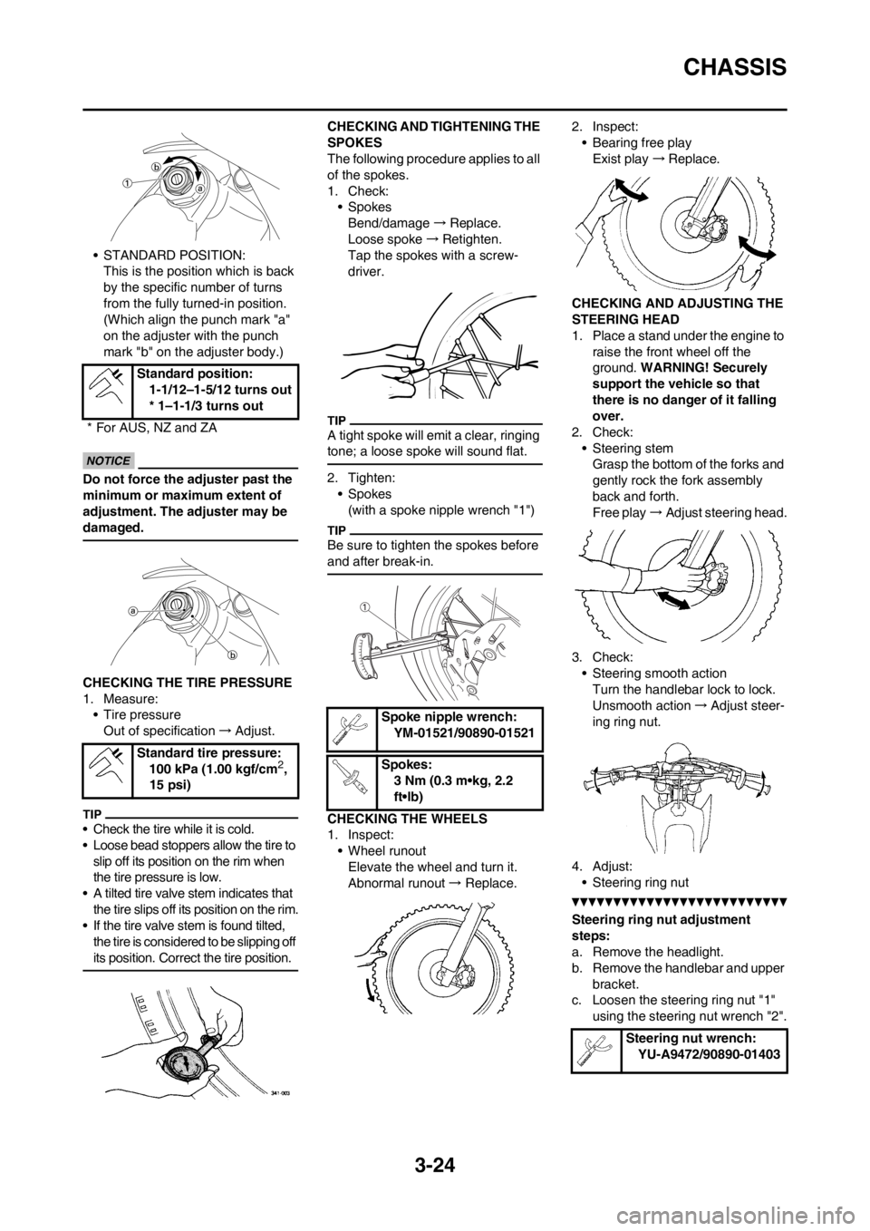
3-24
CHASSIS
• STANDARD POSITION:
This is the position which is back
by the specific number of turns
from the fully turned-in position.
(Which align the punch mark "a"
on the adjuster with the punch
mark "b" on the adjuster body.)
Do not force the adjuster past the
minimum or maximum extent of
adjustment. The adjuster may be
damaged.
CHECKING THE TIRE PRESSURE
1. Measure:
• Tire pressure
Out of specification→Adjust.
• Check the tire while it is cold.
• Loose bead stoppers allow the tire to
slip off its position on the rim when
the tire pressure is low.
• A tilted tire valve stem indicates that
the tire slips off its position on the rim.
• If the tire valve stem is found tilted,
the tire is considered to be slipping off
its position. Correct the tire position.
CHECKING AND TIGHTENING THE
SPOKES
The following procedure applies to all
of the spokes.
1. Check:
• Spokes
Bend/damage→Replace.
Loose spoke→Retighten.
Tap the spokes with a screw-
driver.
A tight spoke will emit a clear, ringing
tone; a loose spoke will sound flat.
2. Tighten:
• Spokes
(with a spoke nipple wrench "1")
Be sure to tighten the spokes before
and after break-in.
CHECKING THE WHEELS
1. Inspect:
• Wheel runout
Elevate the wheel and turn it.
Abnormal runout→ Replace.2. Inspect:
• Bearing free play
Exist play→Replace.
CHECKING AND ADJUSTING THE
STEERING HEAD
1. Place a stand under the engine to
raise the front wheel off the
ground. WARNING! Securely
support the vehicle so that
there is no danger of it falling
over.
2. Check:
• Steering stem
Grasp the bottom of the forks and
gently rock the fork assembly
back and forth.
Free play→Adjust steering head.
3. Check:
• Steering smooth action
Turn the handlebar lock to lock.
Unsmooth action→Adjust steer-
ing ring nut.
4. Adjust:
• Steering ring nut
Steering ring nut adjustment
steps:
a. Remove the headlight.
b. Remove the handlebar and upper
bracket.
c. Loosen the steering ring nut "1"
using the steering nut wrench "2". Standard position:
1-1/12–1-5/12 turns out
* 1–1-1/3 turns out
* For AUS, NZ and ZA
Standard tire pressure:
100 kPa (1.00 kgf/cm
2,
15 psi)
Spoke nipple wrench:
YM-01521/90890-01521
Spokes:
3 Nm (0.3 m•kg, 2.2
ft•lb)
Steering nut wrench:
YU-A9472/90890-01403
Page 125 of 230
5-24
VALVES AND VALVE SPRINGS
h. Press the valve through the valve
guide and onto the valve seat to
make a clear pattern.
i. Measure the valve seat width
again. If the valve seat width is out
of specification, reface and relap
the valve seat.
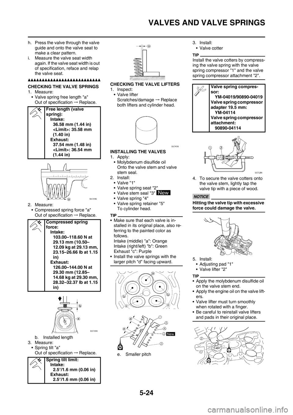
CHECKING THE VALVE SPRINGS
1. Measure:
• Valve spring free length "a"
Out of specification→Replace.
2. Measure:
• Compressed spring force "a"
Out of specification→Replace.
b. Installed length
3. Measure:
• Spring tilt "a"
Out of specification→Replace.CHECKING THE VALVE LIFTERS
1. Inspect:
• Valve lifter
Scratches/damage→Replace
both lifters and cylinder head.
INSTALLING THE VALVES
1. Apply:
• Molybdenum disulfide oil
Onto the valve stem and valve
stem seal.
2. Install:
• Valve "1"
• Valve spring seat "2"
• Valve stem seal "3"
• Valve spring "4"
• Valve spring retainer "5"
To cylinder head.
• Make sure that each valve is in-
stalled in its original place, also re-
ferring to the painted color as
follows.
Intake (middle) "a": Orange
Intake (right/left) "b": Green
Exhaust "c": Purple
• Install the valve springs with the
larger pitch "d" facing upward.
e. Smaller pitch3. Install:
• Valve cotter
Install the valve cotters by compress-
ing the valve spring with the valve
spring compressor "1" and the valve
spring compressor attachment "2".
4. To secure the valve cotters onto
the valve stem, lightly tap the
valve tip with a piece of wood.
Hitting the valve tip with excessive
force could damage the valve.
5. Install:
• Adjusting pad "1"
• Valve lifter "2"
• Apply the molybdenum disulfide oil
on the valve stem end.
• Apply the engine oil on the valve lift-
ers.
• Valve lifter must turn smoothly
when rotated with a finger.
• Be careful to reinstall valve lifters
and pads in their original place.
Free length (valve
spring):
Intake:
36.58 mm (1.44 in)
(1.40 in)
Exhaust:
37.54 mm (1.48 in)
(1.44 in)
Compressed spring
force:
Intake:
103.00–118.60 N at
29.13 mm (10.50–
12.09 kg at 29.13 mm,
23.15–26.66 lb at 1.15
in)
Exhaust:
126.00–144.00 N at
29.30 mm (12.85–
14.68 kg at 29.30 mm,
28.32–32.37 lb at 1.15
in)
Spring tilt limit:
Intake:
2.5°/1.6 mm (0.06 in)
Exhaust:
2.5°/1.6 mm (0.06 in)
Valve spring compres-
sor:
YM-04019/90890-04019
Valve spring compressor
adapter 19.5 mm:
YM-04114
Valve spring compressor
attachment:
90890-04114
Page 157 of 230
5-56
ENGINE REMOVAL
HANDLING NOTE
Support the machine securely so
there is no danger of it falling over.
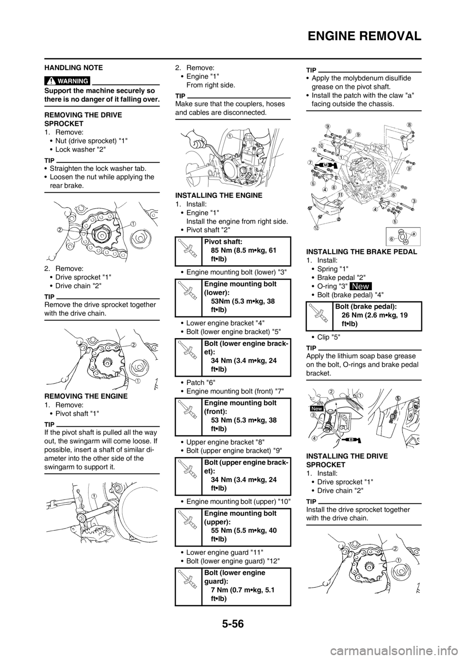
REMOVING THE DRIVE
SPROCKET
1. Remove:
• Nut (drive sprocket) "1"
• Lock washer "2"
• Straighten the lock washer tab.
• Loosen the nut while applying the
rear brake.
2. Remove:
• Drive sprocket "1"
• Drive chain "2"
Remove the drive sprocket together
with the drive chain.
REMOVING THE ENGINE
1. Remove:
• Pivot shaft "1"
If the pivot shaft is pulled all the way
out, the swingarm will come loose. If
possible, insert a shaft of similar di-
ameter into the other side of the
swingarm to support it.
2. Remove:
• Engine "1"
From right side.
Make sure that the couplers, hoses
and cables are disconnected.
INSTALLING THE ENGINE
1. Install:
• Engine "1"
Install the engine from right side.
• Pivot shaft "2"
• Engine mounting bolt (lower) "3"
• Lower engine bracket "4"
• Bolt (lower engine bracket) "5"
• Patch "6"
• Engine mounting bolt (front) "7"
• Upper engine bracket "8"
• Bolt (upper engine bracket) "9"
• Engine mounting bolt (upper) "10"
• Lower engine guard "11"
• Bolt (lower engine guard) "12"
• Apply the molybdenum disulfide
grease on the pivot shaft.
• Install the patch with the claw "a"
facing outside the chassis.
INSTALLING THE BRAKE PEDAL
1. Install:
• Spring "1"
• Brake pedal "2"
• O-ring "3"
• Bolt (brake pedal) "4"
• Clip "5"
Apply the lithium soap base grease
on the bolt, O-rings and brake pedal
bracket.
INSTALLING THE DRIVE
SPROCKET
1. Install:
• Drive sprocket "1"
• Drive chain "2"
Install the drive sprocket together
with the drive chain.
Pivot shaft:
85 Nm (8.5 m•kg, 61
ft•lb)
Engine mounting bolt
(lower):
53Nm (5.3 m•kg, 38
ft•lb)
Bolt (lower engine brack-
et):
34 Nm (3.4 m•kg, 24
ft•lb)
Engine mounting bolt
(front):
53 Nm (5.3 m•kg, 38
ft•lb)
Bolt (upper engine brack-
et):
34 Nm (3.4 m•kg, 24
ft•lb)
Engine mounting bolt
(upper):
55 Nm (5.5 m•kg, 40
ft•lb)
Bolt (lower engine
guard):
7 Nm (0.7 m•kg, 5.1
ft•lb)
Bolt (brake pedal):
26 Nm (2.6 m•kg, 19
ft•lb)