stop start YAMAHA WR 250F 2015 User Guide
[x] Cancel search | Manufacturer: YAMAHA, Model Year: 2015, Model line: WR 250F, Model: YAMAHA WR 250F 2015Pages: 430, PDF Size: 14.14 MB
Page 71 of 430
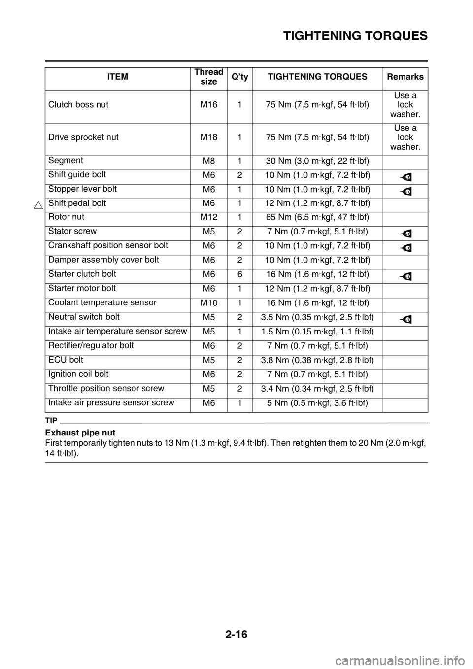
TIGHTENING TORQUES
2-16
TIP
Exhaust pipe nut
First temporarily tighten nuts to 13 Nm (1.3 m·kgf, 9.4 ft·lbf). Then retighten them to 20 Nm (2.0 m·kgf,
14 ft·lbf).Clutch boss nut M16 1 75 Nm (7.5 m·kgf, 54 ft·lbf)Use a
lock
washer.
Drive sprocket nut M18 1 75 Nm (7.5 m·kgf, 54 ft·lbf)Use a
lock
washer.
Segment
M8 1 30 Nm (3.0 m·kgf, 22 ft·lbf)
Shift guide bolt
M6 2 10 Nm (1.0 m·kgf, 7.2 ft·lbf)
Stopper lever bolt
M6 1 10 Nm (1.0 m·kgf, 7.2 ft·lbf)
Shift pedal bolt M6 1 12 Nm (1.2 m·kgf, 8.7 ft·lbf)
Rotor nut
M12 1 65 Nm (6.5 m·kgf, 47 ft·lbf)
Stator screw
M5 2 7 Nm (0.7 m·kgf, 5.1 ft·lbf)
Crankshaft position sensor bolt
M6 2 10 Nm (1.0 m·kgf, 7.2 ft·lbf)
Damper assembly cover bolt
M6 2 10 Nm (1.0 m·kgf, 7.2 ft·lbf)
Starter clutch bolt
M6 6 16 Nm (1.6 m·kgf, 12 ft·lbf)
Starter motor bolt
M6 1 12 Nm (1.2 m·kgf, 8.7 ft·lbf)
Coolant temperature sensor
M10 1 16 Nm (1.6 m·kgf, 12 ft·lbf)
Neutral switch bolt
M5 2 3.5 Nm (0.35 m·kgf, 2.5 ft·lbf)
Intake air temperature sensor screw
M5 1 1.5 Nm (0.15 m·kgf, 1.1 ft·lbf)
Rectifier/regulator bolt
M6 2 7 Nm (0.7 m·kgf, 5.1 ft·lbf)
ECU bolt
M5 2 3.8 Nm (0.38 m·kgf, 2.8 ft·lbf)
Ignition coil bolt
M6 2 7 Nm (0.7 m·kgf, 5.1 ft·lbf)
Throttle position sensor screw
M5 2 3.4 Nm (0.34 m·kgf, 2.5 ft·lbf)
Intake air pressure sensor screw
M6 1 5 Nm (0.5 m·kgf, 3.6 ft·lbf) ITEMThread
sizeQ’ty TIGHTENING TORQUES Remarks
LT
LT
LT
LT
LT
LT
Page 72 of 430
TIGHTENING TORQUES
2-17
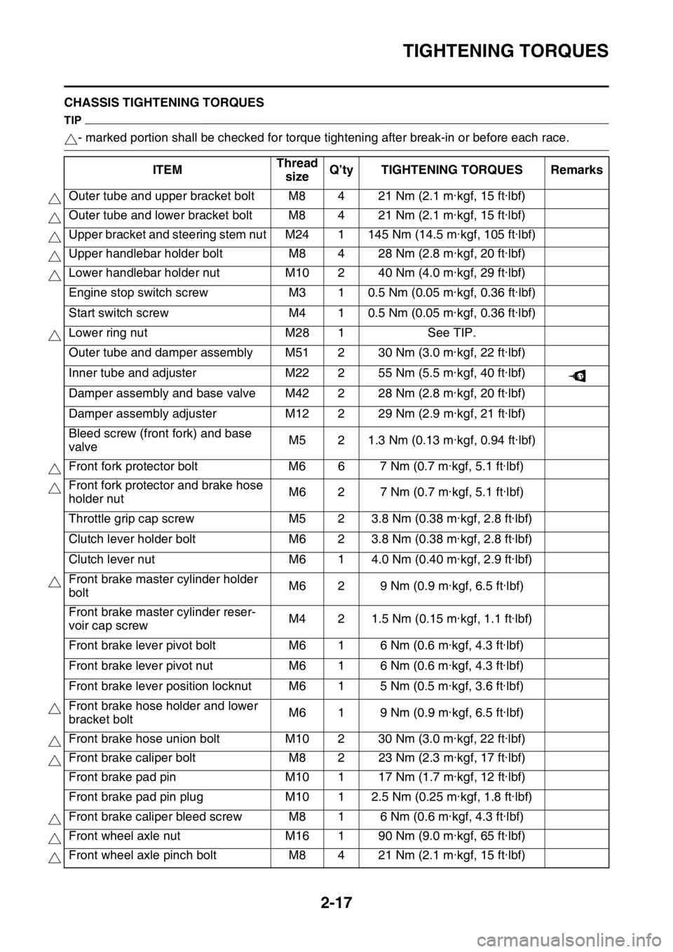
EAS2GB2069CHASSIS TIGHTENING TORQUES
TIP
- marked portion shall be checked for torque tightening after break-in or before each race.
ITEMThread
sizeQ’ty TIGHTENING TORQUES Remarks
Outer tube and upper bracket bolt M8 4 21 Nm (2.1 m·kgf, 15 ft·lbf)
Outer tube and lower bracket bolt M8 4 21 Nm (2.1 m·kgf, 15 ft·lbf)
Upper bracket and steering stem nut M24 1 145 Nm (14.5 m·kgf, 105 ft·lbf)
Upper handlebar holder bolt M8 4 28 Nm (2.8 m·kgf, 20 ft·lbf)
Lower handlebar holder nut M10 2 40 Nm (4.0 m·kgf, 29 ft·lbf)
Engine stop switch screw M3 1 0.5 Nm (0.05 m·kgf, 0.36 ft·lbf)
Start switch screw M4 1 0.5 Nm (0.05 m·kgf, 0.36 ft·lbf)
Lower ring nut M28 1 See TIP.
Outer tube and damper assembly M51 2 30 Nm (3.0 m·kgf, 22 ft·lbf)
Inner tube and adjuster M22 2 55 Nm (5.5 m·kgf, 40 ft·lbf)
Damper assembly and base valve M42 2 28 Nm (2.8 m·kgf, 20 ft·lbf)
Damper assembly adjuster M12 2 29 Nm (2.9 m·kgf, 21 ft·lbf)
Bleed screw (front fork) and base
valveM5 2 1.3 Nm (0.13 m·kgf, 0.94 ft·lbf)
Front fork protector bolt M6 6 7 Nm (0.7 m·kgf, 5.1 ft·lbf)
Front fork protector and brake hose
holder nutM6 2 7 Nm (0.7 m·kgf, 5.1 ft·lbf)
Throttle grip cap screw M5 2 3.8 Nm (0.38 m·kgf, 2.8 ft·lbf)
Clutch lever holder bolt M6 2 3.8 Nm (0.38 m·kgf, 2.8 ft·lbf)
Clutch lever nut M6 1 4.0 Nm (0.40 m·kgf, 2.9 ft·lbf)
Front brake master cylinder holder
boltM6 2 9 Nm (0.9 m·kgf, 6.5 ft·lbf)
Front brake master cylinder reser-
voir cap screwM4 2 1.5 Nm (0.15 m·kgf, 1.1 ft·lbf)
Front brake lever pivot bolt M6 1 6 Nm (0.6 m·kgf, 4.3 ft·lbf)
Front brake lever pivot nut M6 1 6 Nm (0.6 m·kgf, 4.3 ft·lbf)
Front brake lever position locknut M6 1 5 Nm (0.5 m·kgf, 3.6 ft·lbf)
Front brake hose holder and lower
bracket boltM6 1 9 Nm (0.9 m·kgf, 6.5 ft·lbf)
Front brake hose union bolt M10 2 30 Nm (3.0 m·kgf, 22 ft·lbf)
Front brake caliper bolt M8 2 23 Nm (2.3 m·kgf, 17 ft·lbf)
Front brake pad pin M10 1 17 Nm (1.7 m·kgf, 12 ft·lbf)
Front brake pad pin plug M10 1 2.5 Nm (0.25 m·kgf, 1.8 ft·lbf)
Front brake caliper bleed screw M8 1 6 Nm (0.6 m·kgf, 4.3 ft·lbf)
Front wheel axle nut M16 1 90 Nm (9.0 m·kgf, 65 ft·lbf)
Front wheel axle pinch bolt M8 4 21 Nm (2.1 m·kgf, 15 ft·lbf)
LT
Page 89 of 430

CABLE ROUTING DIAGRAM
2-34
1. Clutch cable
2. Throttle cable (return)
3. Throttle cable (pull)
4. Engine stop switch lead
5. Coupler for connecting optional part
6. Engine stop switch coupler
7. Rectifier/regulator coupler
8. AC magneto lead
9. Starter knob/idle screw
10. Starter motor lead
11. Radiator fan fuse
12. Taillight
13. Headlight relay (yellow tape)
14. Starting circuit cut-off relay (no identification
tape)
15. Diode
16. Holder plate
17. Left of the vehicle:radiator fan motor relay (blue
tape)
Right of the vehicle:main relay (red tape)
18. Neutral switch lead
19. Engine bracket
20. Front engine bracket
21. Plastic locking tie
22. Radiator hose
23. Neutral switch coupler
24. Crankshaft position sensor coupler
25. Tension arm
26. Wire harness
27. Tank rail
28. Rectifier/regulator
29. Rectifier/regulator bracket
30. Rear frame
31. Side cover 5
32. Crankcase cover
33. Crankcase
34. Lead holder
35. Frame
A. Pass the engine stop switch lead between the
frame and the cable holder.
B. Insert the coupler for connecting optional part into
the connector, and fix it to the bracket.
C. Insert and fix the engine stop switch coupler to
the bracket.
D. Insert and fix the rectifier/regulator coupler to the
bracket.
E. Pass the AC magneto lead to the front of the ve-
hicle beyond the starter knob/idle screw and to
the rear of the vehicle beyond the radiator. No
pinch is allowed between the radiator and the
tension arm.
F. Place the rear grommet of the starter motor lead
matching the rear end of the side cover.
G. Insert the radiator fan motor fuse into the protru-
sion of the holder plate.
H. Place the diode on top of the rear fender on the
inner side of the rear frame.
I. Bring the neutral switch lead into line with the
crankcase cover with no sag allowed.
J. Route the AC magneto lead under the starter
clutch cover.
K. Pass the neutral switch lead to the inside of the
front engine bracket (the side of the vehicle).
L. Insert the plastic locking tie into the bracket hole
and clamp the clutch cable. Clamp it so that the
lock of the plastic locking tie faces downward,
and then cut off the end of the plastic locking tie.
M. Pass the clutch cable with no downward sag al-
lowed.N. Place the grommet of the clutch cable so that it
contacts the radiator hose. Route the clutch cable
outside the neutral switch lead, AC magneto lead
and starter motor lead.
O. Route each lead so that the leads are not pinched
between the radiator hose and the frame.
P. 40 mm (1.57 in)
Q. Clamp the clutch cable, AC magneto lead, neu-
tral switch lead and starter motor lead by the plas-
tic locking tie. Make sure that they are clamped at
the positioning tapes in the clutch cable and the
starter motor lead. Make the lock on the plastic
locking tie face the front of the vehicle, and cut
the end.
R. Clamp the starter motor lead to the inside of the
tension arm with a plastic locking tie. Clamp it so
that the lock of the plastic locking tie faces up-
ward and outward, and do not cut off the end of
the plastic locking tie. Route the lead so that there
is no slack at the bottom from the clamp position
onwards.
S. After connecting the neutral switch coupler, at-
tach the coupler cover.
T. After connecting the crankshaft position sensor
coupler, attach the coupler cover.
U. Pass the rectifier/regulator lead to the inside of
the tension arm (the side of the vehicle).
V. Pass the main harness to the front of the radiator
hose (the front of the vehicle), and to the inside of
the clutch cable (the side of the vehicle).
W. Pass the engine stop switch lead between the
coupler for connecting optional part and the tank
rail, with the lead on the main harness side facing
the top of the vehicle.
X. Insert the starter motor lead completely into the
end of the side cover 5.
Y. Clamp the clutch cable at the front of the lead (the
front of the vehicle).
Z. Insert the clip of the plastic locking tie into the
frame. Face the lock of the plastic locking tie for-
ward, and then cut off the end.
Page 97 of 430

CABLE ROUTING DIAGRAM
2-42
1. Clutch switch lead
2. Engine stop switch lead
3. Clutch cable
4. Brake hose guide
5. Headlight lead
6. Speed sensor lead
7. Indicator light coupler
8. Meter assembly optional switch coupler
9. Meter assembly coupler
10. Speed sensor coupler
11. Start switch lead
12. Plastic band
13. Throttle cable
14. Front brake hose
A. Route the throttle cable, clutch cable, clutch
switch lead, engine stop switch lead and start
switch lead between the cable guide of the meter
bracket and handle crown. The cables and leads
may be routed in any order.
B. Clamp the wire harness, clutch switch lead and
start switch lead to the meter bracket. The clamp
shall be located at a position where there is no
slack with the handle turned fully to the left.
C. Connect the headlight lead to the headlight.
D. Clamp the start switch lead to the handlebar by
the plastic band.
E. Clamp the engine stop switch lead and clutch
switch lead to the handlebar by the plastic band.
F. 40°±10°
G. Vertical direction
H. Pass the engine stop switch lead under the han-
dlebar.
Page 114 of 430
ENGINE
3-10
EAS2GB2083
ENGINE
EAS2GB2084CHECKING THE COOLANT LEVELEWA
WARNING
If coolant seems hot, do not remove the ra-
diator cap.
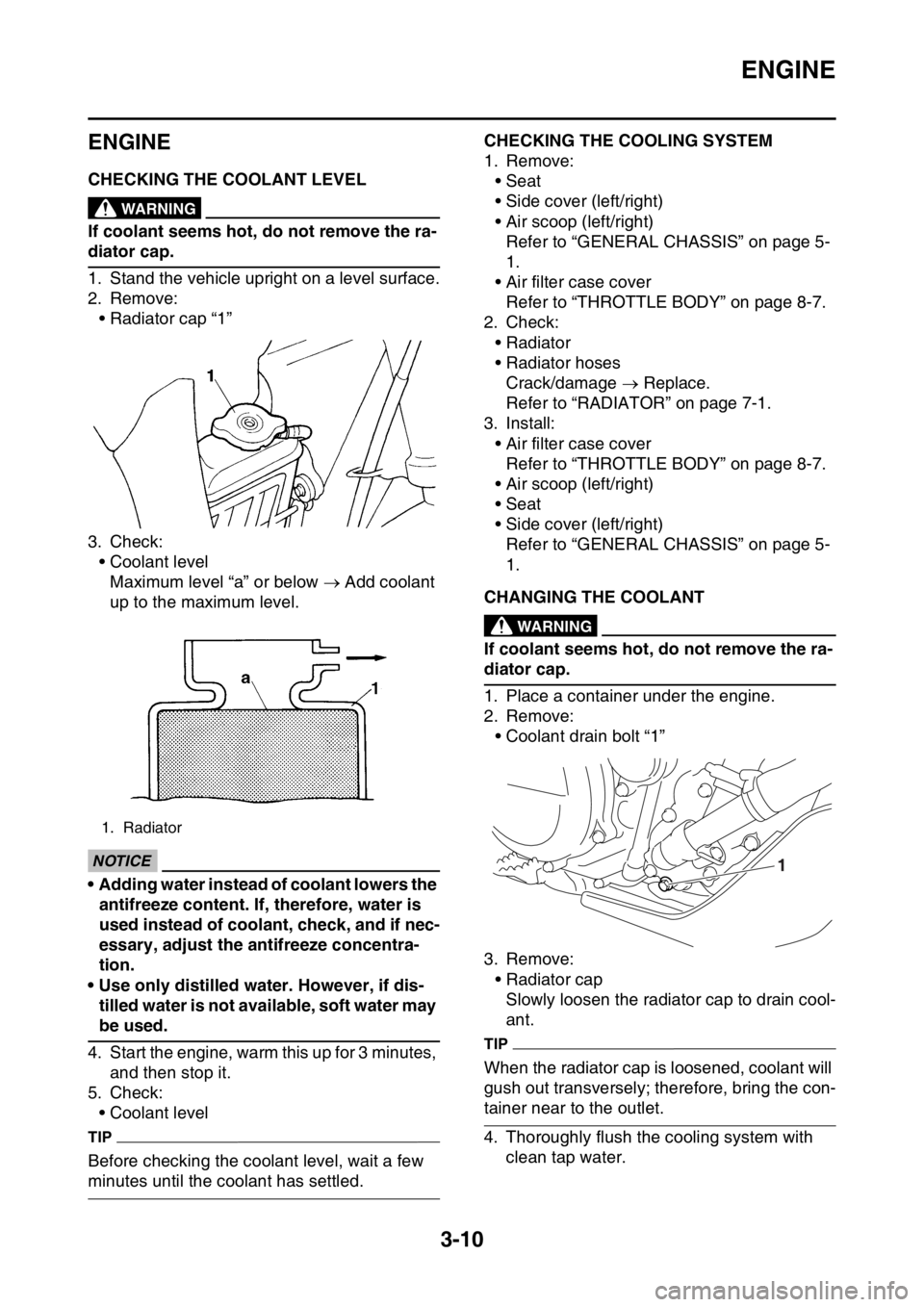
1. Stand the vehicle upright on a level surface.
2. Remove:
• Radiator cap “1”
3. Check:
• Coolant level
Maximum level “a” or below Add coolant
up to the maximum level.
ECA
NOTICE
• Adding water instead of coolant lowers the
antifreeze content. If, therefore, water is
used instead of coolant, check, and if nec-
essary, adjust the antifreeze concentra-
tion.
• Use only distilled water. However, if dis-
tilled water is not available, soft water may
be used.
4. Start the engine, warm this up for 3 minutes,
and then stop it.
5. Check:
• Coolant level
TIP
Before checking the coolant level, wait a few
minutes until the coolant has settled.
EAS2GB2085CHECKING THE COOLING SYSTEM
1. Remove:
• Seat
• Side cover (left/right)
• Air scoop (left/right)
Refer to “GENERAL CHASSIS” on page 5-
1.
• Air filter case cover
Refer to “THROTTLE BODY” on page 8-7.
2. Check:
• Radiator
• Radiator hoses
Crack/damage Replace.
Refer to “RADIATOR” on page 7-1.
3. Install:
• Air filter case cover
Refer to “THROTTLE BODY” on page 8-7.
• Air scoop (left/right)
• Seat
• Side cover (left/right)
Refer to “GENERAL CHASSIS” on page 5-
1.
EAS2GB2086CHANGING THE COOLANTEWA
WARNING
If coolant seems hot, do not remove the ra-
diator cap.
1. Place a container under the engine.
2. Remove:
• Coolant drain bolt “1”
3. Remove:
• Radiator cap
Slowly loosen the radiator cap to drain cool-
ant.
TIP
When the radiator cap is loosened, coolant will
gush out transversely; therefore, bring the con-
tainer near to the outlet.
4. Thoroughly flush the cooling system with
clean tap water.
1. Radiator
1
Page 115 of 430
ENGINE
3-11
5. Install:
• Copper washer
• Coolant drain bolt
6. Pour coolant.
EWA
WARNING
• If coolant splashes in your eyes, thorough-
ly wash them with water and consult a
doctor.
• If coolant splashes on your clothes, quick-
ly wash it away with water and then with
soap and water.
• If coolant is swallowed, induce vomiting
and get immediate medical attention.
ECA
NOTICE
• Adding water instead of coolant lowers the
antifreeze content of the coolant. If water
is used instead of coolant check, and if
necessary, correct the antifreeze concen-
tration of the coolant.
• Use only distilled water. However, if dis-
tilled water is not available, soft water may
be used.
• If coolant comes into contact with painted
surfaces, immediately wash them with wa-
ter.
• Do not mix different types of antifreeze.
7. Install:
• Radiator cap
8. Start the engine, warm this up for 3 minutes,
stop it, and then wait for it to cool down.
9. Check:
• Coolant level
Refer to “CHECKING THE COOLANT LEV-
EL” on page 3-10.
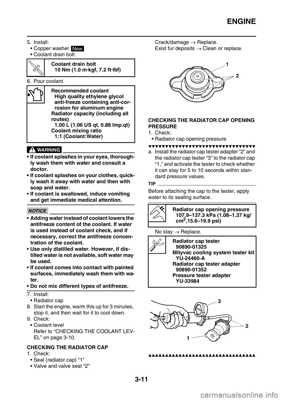
EAS2GB2087CHECKING THE RADIATOR CAP
1. Check:
• Seal (radiator cap) “1”
• Valve and valve seat “2”Crack/damage Replace.
Exist fur deposits Clean or replace.
EAS2GB2088CHECKING THE RADIATOR CAP OPENING
PRESSURE
1. Check:
• Radiator cap opening pressure
▼▼▼▼▼▼▼▼▼▼▼▼▼▼▼▼▼▼▼▼▼▼▼▼▼▼▼▼▼▼▼▼
a. Install the radiator cap tester adapter “2” and
the radiator cap tester “3” to the radiator cap
“1,” and activate the tester to check whether
it can stay for 5 to 10 seconds within stan-
dard pressure values.
TIP
Before attaching the cap to the tester, apply
water to its sealing surface.
No stay Replace.
▲▲▲▲▲▲▲▲▲▲▲▲▲▲▲▲▲▲▲▲▲▲▲▲▲▲▲▲▲▲▲▲
Coolant drain bolt
10 Nm (1.0 m·kgf, 7.2 ft·lbf)
Recommended coolant
High quality ethylene glycol
anti-freeze containing anti-cor-
rosion for aluminum engine
Radiator capacity (including all
routes)
1.00 L (1.06 US qt, 0.88 Imp.qt)
Coolant mixing ratio
1:1 (Coolant:Water)
New
T R..
Radiator cap opening pressure
107.9–137.3 kPa (1.08–1.37 kg/
cm
2,15.6–19.9 psi)
Radiator cap tester
90890-01325
Mityvac cooling system tester kit
YU-24460-A
Radiator cap tester adapter
90890-01352
Pressure tester adapter
YU-33984
Page 120 of 430
ENGINE
3-16
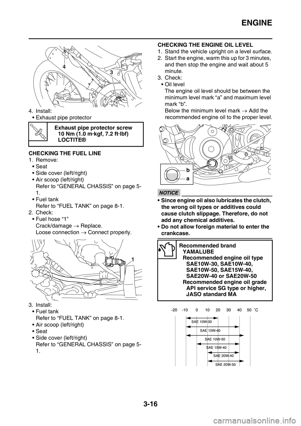
4. Install:
• Exhaust pipe protector
EAS2GB2097CHECKING THE FUEL LINE
1. Remove:
• Seat
• Side cover (left/right)
• Air scoop (left/right)
Refer to “GENERAL CHASSIS” on page 5-
1.
• Fuel tank
Refer to “FUEL TANK” on page 8-1.
2. Check:
• Fuel hose “1”
Crack/damage Replace.
Loose connection Connect properly.
3. Install:
• Fuel tank
Refer to “FUEL TANK” on page 8-1.
• Air scoop (left/right)
• Seat
• Side cover (left/right)
Refer to “GENERAL CHASSIS” on page 5-
1.
EAS2GB2098
CHECKING THE ENGINE OIL LEVEL
1. Stand the vehicle upright on a level surface.
2. Start the engine, warm this up for 3 minutes,
and then stop the engine and wait about 5
minute.
3. Check:
• Oil level
The engine oil level should be between the
minimum level mark “a” and maximum level
mark “b”.
Below the minimum level mark Add the
recommended engine oil to the proper level.
ECA
NOTICE
• Since engine oil also lubricates the clutch,
the wrong oil types or additives could
cause clutch slippage. Therefore, do not
add any chemical additives.
• Do not allow foreign material to enter the
crankcase. Exhaust pipe protector screw
10 Nm (1.0 m·kgf, 7.2 ft·lbf)
LOCTITE®
4
3
T R..
1
Recommended brand
YAMALUBE
Recommended engine oil type
SAE10W-30, SAE10W-40,
SAE10W-50, SAE15W-40,
SAE20W-40 or SAE20W-50
Recommended engine oil grade
API service SG type or higher,
JASO standard MA
a b
Page 121 of 430
ENGINE
3-17
EAS2GB2099CHANGING THE ENGINE OIL
Stand the vehicle upright on a level surface.
1. Start the engine, warm this up for 3 minutes,
and then stop the engine and wait about 5
minutes.
2. Place an oil pan under the drain bolt.
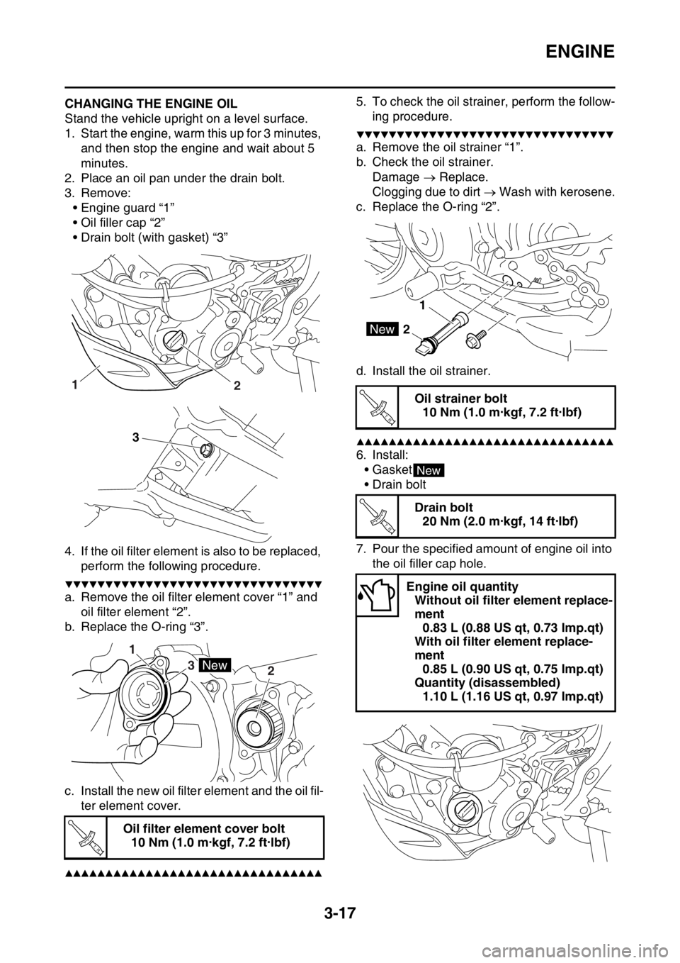
3. Remove:
• Engine guard “1”
• Oil filler cap “2”
• Drain bolt (with gasket) “3”
4. If the oil filter element is also to be replaced,
perform the following procedure.
▼▼▼▼▼▼▼▼▼▼▼▼▼▼▼▼▼▼▼▼▼▼▼▼▼▼▼▼▼▼▼▼
a. Remove the oil filter element cover “1” and
oil filter element “2”.
b. Replace the O-ring “3”.
c. Install the new oil filter element and the oil fil-
ter element cover.
▲▲▲▲▲▲▲▲▲▲▲▲▲▲▲▲▲▲▲▲▲▲▲▲▲▲▲▲▲▲▲▲
5. To check the oil strainer, perform the follow-
ing procedure.
▼▼▼▼▼▼▼▼▼▼▼▼▼▼▼▼▼▼▼▼▼▼▼▼▼▼▼▼▼▼▼▼
a. Remove the oil strainer “1”.
b. Check the oil strainer.
Damage Replace.
Clogging due to dirt Wash with kerosene.
c. Replace the O-ring “2”.
d. Install the oil strainer.
▲▲▲▲▲▲▲▲▲▲▲▲▲▲▲▲▲▲▲▲▲▲▲▲▲▲▲▲▲▲▲▲
6. Install:
•Gasket
• Drain bolt
7. Pour the specified amount of engine oil into
the oil filler cap hole.
Oil filter element cover bolt
10 Nm (1.0 m·kgf, 7.2 ft·lbf)
12
3
1
3
2
New
T R..
Oil strainer bolt
10 Nm (1.0 m·kgf, 7.2 ft·lbf)
Drain bolt
20 Nm (2.0 m·kgf, 14 ft·lbf)
Engine oil quantity
Without oil filter element replace-
ment
0.83 L (0.88 US qt, 0.73 Imp.qt)
With oil filter element replace-
ment
0.85 L (0.90 US qt, 0.75 Imp.qt)
Quantity (disassembled)
1.10 L (1.16 US qt, 0.97 Imp.qt)
1
2New
T R..
New
T R..
Page 191 of 430

HANDLEBAR
5-33
EAS2GB2195
HANDLEBAR
Removing the handlebar
Order Part name Q’ty Remarks
1 Clutch cable 1 Disconnect.
2 Clutch switch 1
3 Clutch lever holder 1
4 Engine stop switch 1
5 Brake master cylinder 1
6 Throttle cable cap 1
7 Throttle cable (pull) 1 Disconnect.
8 Throttle cable (return) 1 Disconnect.
9 Right grip 1
10 Tube guide 1
11 Start switch 1
12 Left grip 1
13 Handlebar upper holder 2
14 Handlebar 1
Page 230 of 430

CLUTCH......................................................................................................... 6-40
REMOVING THE CLUTCH ...................................................................... 6-43
CHECKING THE FRICTION PLATES...................................................... 6-43
CHECKING THE CLUTCH PLATES ........................................................ 6-43
CHECKING THE CLUTCH SPRINGS...................................................... 6-43
CHECKING THE CLUTCH HOUSING ..................................................... 6-44
CHECKING THE CLUTCH BOSS ............................................................ 6-44
CHECKING THE PRESSURE PLATE ..................................................... 6-44
CHECKING THE PUSH LEVER SHAFT .................................................. 6-44
CHECKING THE CLUTCH PUSH RODS ................................................ 6-44
CHECKING THE PRIMARY DRIVE GEAR .............................................. 6-44
CHECKING THE PRIMARY DRIVEN GEAR ........................................... 6-45
INSTALLING THE OIL SEAL................................................................... 6-45
INSTALLING THE RIGHT CRANKCASE COVER ................................... 6-45
INSTALLING THE CLUTCH ..................................................................... 6-45
INSTALLING THE KICKSTARTER LEVER ............................................. 6-48
KICKSTATER................................................................................................. 6-49
REMOVING THE KICK SHAFT ASSEMBLY ........................................... 6-50
CHECKING THE KICK SHAFT AND RATCHET WHEEL ........................ 6-50
CHECKING THE KICK GEAR, KICK IDLE GEAR AND RATCHET
WHEEL .................................................................................................... 6-50
INSTALLING THE KICK SHAFT ASSEMBLY .......................................... 6-50
INSTALLING THE KICK IDLE GEAR ....................................................... 6-51
SHIFT SHAFT................................................................................................. 6-52
REMOVING THE SHIFT GUIDE AND SHIFT LEVER ASSEMBLY ......... 6-53
REMOVING THE SEGMENT ................................................................... 6-53
CHECKING THE SHIFT SHAFT .............................................................. 6-53
CHECKING THE SHIFT GUIDE AND SHIFT LEVER ASSEMBLY ......... 6-53
CHECKING THE STOPPER LEVER ....................................................... 6-53
INSTALLING THE STOPPER LEVER ..................................................... 6-54
INSTALLING THE SEGMENT.................................................................. 6-54
INSTALLING THE SHIFT GUIDE AND SHIFT LEVER ASSEMBLY ....... 6-54
INSTALLING THE SHIFT SHAFT ............................................................ 6-55
INSTALLING THE SHIFT PEDAL ............................................................ 6-55
OIL PUMP AND BALANCER GEAR............................................................. 6-56
REMOVING THE BALANCER ................................................................. 6-58
CHECKING THE PRIMARY DRIVE GEAR, BALANCER SHAFT DRIVE
GEAR, AND BALANCER WEIGHT GEAR .............................................. 6-58
CHECKING THE BALANCER .................................................................. 6-58
CHECKING THE OIL PUMP .................................................................... 6-58
ASSEMBLING THE OIL PUMP ................................................................ 6-59
INSTALLING THE OIL PUMP AND BALANCER GEAR .......................... 6-59