stop start YAMAHA WR 250F 2015 Owner's Manual
[x] Cancel search | Manufacturer: YAMAHA, Model Year: 2015, Model line: WR 250F, Model: YAMAHA WR 250F 2015Pages: 430, PDF Size: 14.14 MB
Page 299 of 430

CRANKCASE
6-68
EAS2GB2312
CRANKCASE
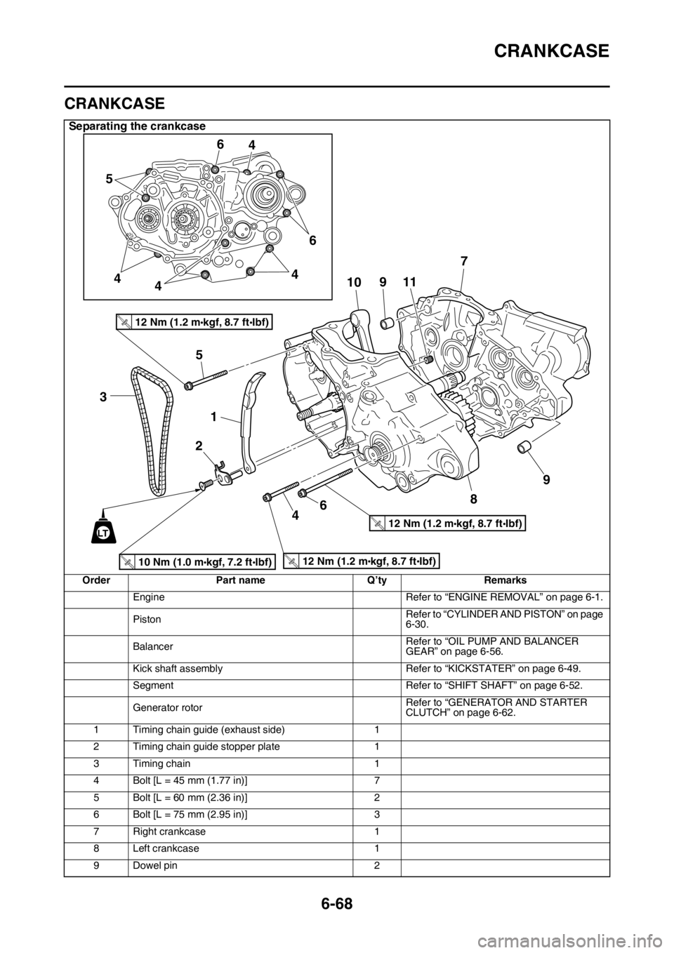
Separating the crankcase
Order Part name Q’ty Remarks
Engine Refer to “ENGINE REMOVAL” on page 6-1.
PistonRefer to “CYLINDER AND PISTON” on page
6-30.
BalancerRefer to “OIL PUMP AND BALANCER
GEAR” on page 6-56.
Kick shaft assembly Refer to “KICKSTATER” on page 6-49.
Segment Refer to “SHIFT SHAFT” on page 6-52.
Generator rotorRefer to “GENERATOR AND STARTER
CLUTCH” on page 6-62.
1 Timing chain guide (exhaust side) 1
2 Timing chain guide stopper plate 1
3 Timing chain 1
4 Bolt [L = 45 mm (1.77 in)] 7
5 Bolt [L = 60 mm (2.36 in)] 2
6 Bolt [L = 75 mm (2.95 in)] 3
7 Right crankcase 1
8 Left crankcase 1
9 Dowel pin 2
10 Nm (1.0 mkgf, 7.2 ftIbf)T.R
.
12 Nm (1.2 mkgf, 8.7 ftIbf)T.R
.
12 Nm (1.2 mkgf, 8.7 ftIbf)T.R
.
12 Nm (1.2 mkgf, 8.7 ftIbf)T.R
.
3
1 5
2
6410 56
4
4
446
9117
8
9
LT
Page 331 of 430

THROTTLE BODY
8-10
EAS2GB2354CHECKING THE INJECTOR
1. Check:
• Injectors
Obstruction Replace, and check the fuel
pump and the fuel injection system.
Refer to “FUEL INJECTION SYSTEM” on
page 9-28.
Deposits Replace.
Damage Replace.
2. Check:
• Injector resistance
Refer to “CHECKING THE FUEL INJEC-
TOR” on page 9-81.
EAS2GB2355CHECKING THE THROTTLE BODY
1. Check:
• Throttle body
Cracks/damage Replace.
2. Check:
• Fuel passages
Obstructions Clean.
ECA
NOTICE
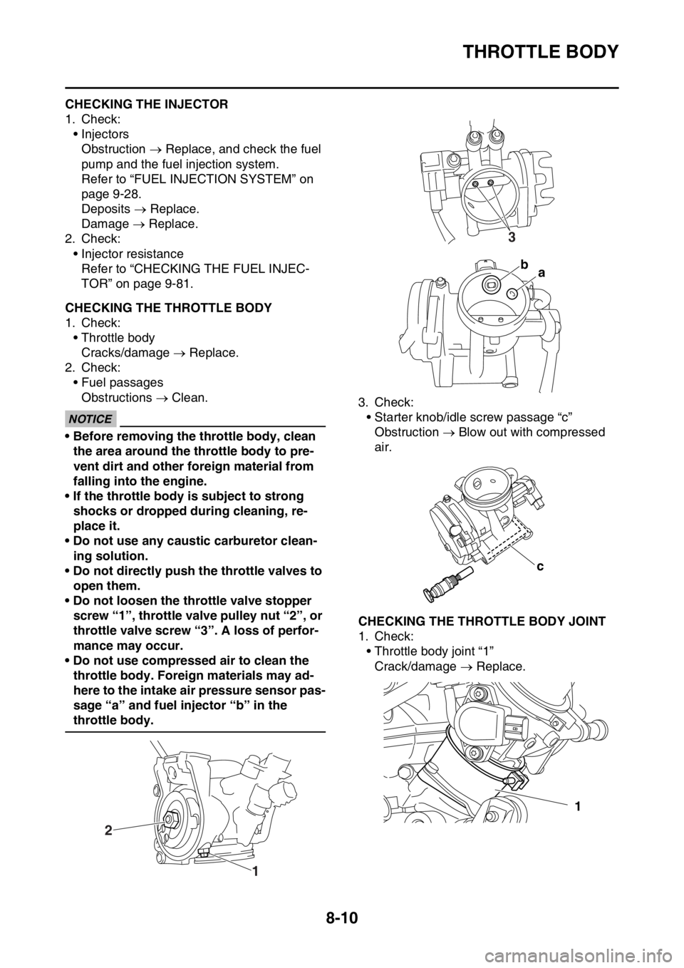
• Before removing the throttle body, clean
the area around the throttle body to pre-
vent dirt and other foreign material from
falling into the engine.
• If the throttle body is subject to strong
shocks or dropped during cleaning, re-
place it.
• Do not use any caustic carburetor clean-
ing solution.
• Do not directly push the throttle valves to
open them.
• Do not loosen the throttle valve stopper
screw “1”, throttle valve pulley nut “2”, or
throttle valve screw “3”. A loss of perfor-
mance may occur.
• Do not use compressed air to clean the
throttle body. Foreign materials may ad-
here to the intake air pressure sensor pas-
sage “a” and fuel injector “b” in the
throttle body.3. Check:
• Starter knob/idle screw passage “c”
Obstruction Blow out with compressed
air.
EAS2GB2356CHECKING THE THROTTLE BODY JOINT
1. Check:
• Throttle body joint “1”
Crack/damage Replace.
1 2
3
ba
c
1
Page 337 of 430

IGNITION SYSTEM
9-3
1. Joint connector
2. Joint connector
4. AC magneto
9. Battery
10.Frame ground
11.Starter relay
12.Main fuse
22.ECU (engine control unit)
23.Ignition coil
24.Spark plug
30.Joint connector
35.Lean angle sensor
36.Engine stop switch
48.Frame ground
Page 341 of 430

ELECTRIC STARTING SYSTEM
9-7
1. Joint connector
2. Joint connector
3. Joint connector
7. Main relay
9. Battery
10.Frame ground
11.Starter relay
12.Main fuse
13.Starter motor
14.Starter relay diode
22.ECU (engine control unit)
30.Joint connector
36.Engine stop switch
37.Neutral switch
38.Diode
39.Starting circuit cut-off relay
40.Clutch switch
41.Start switch
48.Frame ground
Page 345 of 430

ELECTRIC STARTING SYSTEM
9-11
8. Check the main relay.
Refer to “CHECKING THE RE-
LAYS” on page 9-72.NG
Replace the main relay.
OK
9. Check the neutral switch.
Refer to “CHECKING THE
SWITCHES” on page 9-64.NG
Replace the neutral switch.
OK
10.Check the clutch switch.
Refer to “CHECKING THE
SWITCHES” on page 9-64.NG
Replace the clutch switch.
OK
11.Check the engine stop switch.
Refer to “CHECKING THE
SWITCHES” on page 9-64.NG
Replace the start switch.
OK
12.Check the start switch.
Refer to “CHECKING THE
SWITCHES” on page 9-64.NG
Replace the engine stop switch.
OK
13.Check the entire starting system’s
wiring.
Refer to “CIRCUIT DIAGRAM” on
page 9-6.NG
Properly connect or repair the starting sys-
tem’s wiring.
OK
Replace the ECU.
Page 363 of 430

FUEL INJECTION SYSTEM
9-29
1. Joint connector
2. Joint connector
3. Joint connector
4. AC magneto
7. Main relay
9. Battery
10.Frame ground
11.Starter relay
12.Main fuse
15.Indicator light
16.Engine trouble warning light
22.ECU (engine control unit)
25.Injector
30.Joint connector
31.Intake air temperature sensor
32.Coolant temperature sensor
33.Throttle position sensor
34.Intake air pressure sensor
35.Lean angle sensor
36.Engine stop switch
37.Neutral switch
38.Diode
39.Starting circuit cut-off relay
40.Clutch switch
42.Joint connector
48.Frame ground
Page 364 of 430

FUEL INJECTION SYSTEM
9-30
EAS2GB2376ECU SELF-DIAGNOSTIC FUNCTION
The ECU is equipped with a self-diagnostic function in order to ensure that the fuel injection system
is operating normally. If this function detects a malfunction in the system, it immediately operates the
engine under substitute characteristics and illuminates the engine trouble warning light to alert the
rider that a malfunction has occurred in the system. Once a malfunction has been detected, a fault
code number is stored in the memory of the ECU.
• To inform the rider that the fuel injection system is not functioning, the engine trouble warning light
flashes while the start switch is being pushed to start the engine.
• If a malfunction is detected in the system by the self-diagnostic function, the ECU provides an ap-
propriate substitute characteristic operation, and alerts the rider of the detected malfunction by illu-
minating the engine trouble warning light.
Engine trouble warning light indication and fuel injection system operation
* The warning light flashes when any one of the following conditions is present and the start switch
is pushed:
Checking the engine trouble warning light
The engine trouble warning light comes on for around 2 seconds when pushing the start switch to
turn on the meter light and the engine trouble warning light comes on while the start switch is being
pushed.Warning light indica-
tionECU operationFuel injection opera-
tionVehicle operation
Flashing* Warning provided
when unable to start
engineOperation stopped Cannot be operated
Remains on Malfunction detected Operated with substi-
tute characteristics in
accordance with the
description of the mal-
functionCan or cannot be oper-
ated depending on the
fault code
12: Crankshaft position sensor 41: Lean angle sensor
(open or short circuit)
30: Lean angle sensor
(latch up detected)50: ECU internal malfunction
(faulty ECU memory)
33: Ignition coil
(Malfunction detected in the primary wire
of the ignition coil)
a. The meter light does not come on.
b. The meter light comes on.
c. Light OFF
d. Light ON for 2 seconds
ab
c cd
Page 365 of 430

FUEL INJECTION SYSTEM
9-31
ECU detects an abnormal signal from a sensor
If the ECU detects an abnormal signal from a sensor while the vehicle is being driven, the ECU illu-
minates the engine trouble warning light and provides the engine with alternate operating instructions
that are appropriate for the type of malfunction.
When an abnormal signal is received from a sensor, the ECU processes the specified values that are
programmed for each sensor in order to provide the engine with alternate operating instructions that
enable the engine to continue operating or stop operating, depending on the conditions.
EAS2GB2377TROUBLESHOOTING METHOD
The engine operation is not normal and the engine trouble warning light comes on.
1. Check:
• Fault code number
▼▼▼▼▼▼▼▼▼▼▼▼▼▼▼▼▼▼▼▼▼▼▼▼▼▼▼▼▼▼▼▼▼▼▼▼▼▼▼▼▼▼▼▼▼▼▼▼▼▼▼▼▼▼▼▼▼▼▼▼▼▼▼▼▼▼▼▼
a. Connect the Yamaha diagnostic tool. Refer to “YAMAHA DIAGNOSTIC TOOL” on page 9-32.
b. Check the fault code number displayed on the Yamaha diagnostic tool.
c. Identify the faulty system with the fault code number.
d. Identify the probable cause of the malfunction.
▲▲▲▲▲▲▲▲▲▲▲▲▲▲▲▲▲▲▲▲▲▲▲▲▲▲▲▲▲▲▲▲▲▲▲▲▲▲▲▲▲▲▲▲▲▲▲▲▲▲▲▲▲▲▲▲▲▲▲▲▲▲▲▲▲▲▲▲
2. Check and repair the probable cause of the malfunction.
3. Perform the reinstatement action for the fuel injection system. Refer to “Confirmation of service
completion” in the appropriate table in “TROUBLESHOOTING DETAILS” on page 9-35.
4. After pushing the engine stop switch, push the start switch to check whether the fault code no. is
displayed.
TIP
If another fault code number is displayed, repeat steps (1) to (4) until no fault code number is dis-
played.
5. Erase the malfunction history in the diagnostic mode. Refer to “SENSOR OPERATION TABLE”
(Diagnostic code No.62).
TIP
Turning off the meter light will not erase the malfunction history.
The engine operation is not normal, but the engine trouble warning light does not come on.
1. Check the operation of the following sensors and actuators in the diagnostic mode. Refer to
“TROUBLESHOOTING DETAILS” on page 9-35.
If a malfunction is detected in the sensors or actuators, repair or replace all faulty parts.
If no malfunction is detected in the sensors and actuators, check and repair the inner parts of the
engine.Fault code No. No fault code No.
Check and repair. Refer to “TROUBLESHOOT-
ING DETAILS” on page 9-35.
Monitor the operation of the sensors and actua-
tors in the diagnostic mode. Refer to “TROU-
BLESHOOTING DETAILS” on page 9-35 and
“LIST OF SELF-DIAGNOSTIC AND FAIL-SAFE
ACTIONS” on page 10-5.Check and repair.
01: Throttle position sensor signal (throttle angle)
30: Ignition coil
36: Injector
Page 372 of 430

FUEL INJECTION SYSTEM
9-38
TIP
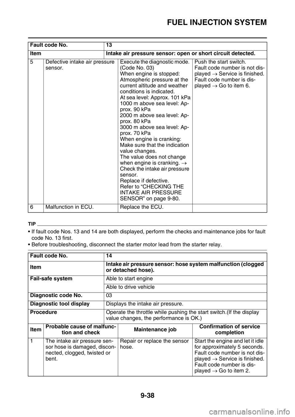
• If fault code Nos. 13 and 14 are both displayed, perform the checks and maintenance jobs for fault
code No. 13 first.
• Before troubleshooting, disconnect the starter motor lead from the starter relay. 5 Defective intake air pressure
sensor.Execute the diagnostic mode.
(Code No. 03)
When engine is stopped:
Atmospheric pressure at the
current altitude and weather
conditions is indicated.
At sea level: Approx. 101 kPa
1000 m above sea level: Ap-
prox. 90 kPa
2000 m above sea level: Ap-
prox. 80 kPa
3000 m above sea level: Ap-
prox. 70 kPa
When engine is cranking:
Make sure that the indication
value changes.
The value does not change
when engine is cranking.
Check the intake air pressure
sensor.
Replace if defective.
Refer to “CHECKING THE
INTAKE AIR PRESSURE
SENSOR” on page 9-80.Push the start switch.
Fault code number is not dis-
played Service is finished.
Fault code number is dis-
played Go to item 6.
6 Malfunction in ECU. Replace the ECU.
Fault code No. 14
ItemIntake air pressure sensor: hose system malfunction (clogged
or detached hose).
Fail-safe systemAble to start engine
Able to drive vehicle
Diagnostic code No.03
Diagnostic tool displayDisplays the intake air pressure.
ProcedureOperate the throttle while pushing the start switch.(If the display
value changes, the performance is OK.)
ItemProbable cause of malfunc-
tion and checkMaintenance jobConfirmation of service
completion
1 The intake air pressure sen-
sor hose is damaged, discon-
nected, clogged, twisted or
bent.Repair or replace the sensor
hose.Start the engine and let it idle
for approximately 5 seconds.
Fault code number is not dis-
played Service is finished.
Fault code number is dis-
played Go to item 2. Fault code No. 13
Item Intake air pressure sensor: open or short circuit detected.
Page 373 of 430

FUEL INJECTION SYSTEM
9-39
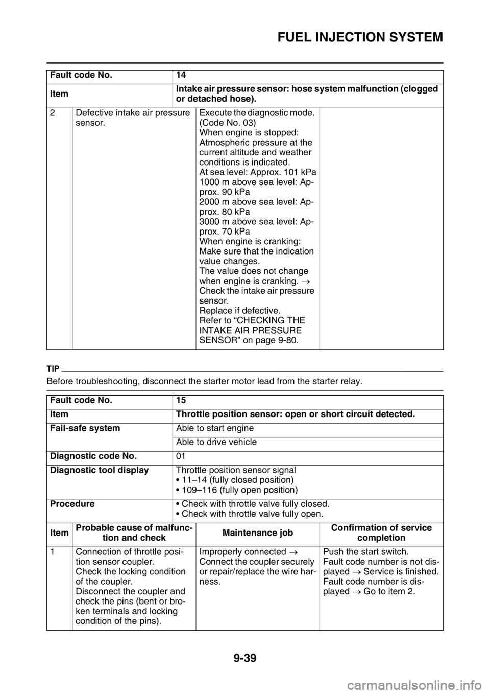
TIP
Before troubleshooting, disconnect the starter motor lead from the starter relay. 2 Defective intake air pressure
sensor.Execute the diagnostic mode.
(Code No. 03)
When engine is stopped:
Atmospheric pressure at the
current altitude and weather
conditions is indicated.
At sea level: Approx. 101 kPa
1000 m above sea level: Ap-
prox. 90 kPa
2000 m above sea level: Ap-
prox. 80 kPa
3000 m above sea level: Ap-
prox. 70 kPa
When engine is cranking:
Make sure that the indication
value changes.
The value does not change
when engine is cranking.
Check the intake air pressure
sensor.
Replace if defective.
Refer to “CHECKING THE
INTAKE AIR PRESSURE
SENSOR” on page 9-80.
Fault code No. 15
Item Throttle position sensor: open or short circuit detected.
Fail-safe systemAble to start engine
Able to drive vehicle
Diagnostic code No.01
Diagnostic tool displayThrottle position sensor signal
• 11–14 (fully closed position)
• 109–116 (fully open position)
Procedure• Check with throttle valve fully closed.
• Check with throttle valve fully open.
ItemProbable cause of malfunc-
tion and checkMaintenance jobConfirmation of service
completion
1 Connection of throttle posi-
tion sensor coupler.
Check the locking condition
of the coupler.
Disconnect the coupler and
check the pins (bent or bro-
ken terminals and locking
condition of the pins).Improperly connected
Connect the coupler securely
or repair/replace the wire har-
ness.Push the start switch.
Fault code number is not dis-
played Service is finished.
Fault code number is dis-
played Go to item 2. Fault code No. 14
ItemIntake air pressure sensor: hose system malfunction (clogged
or detached hose).