YAMAHA WR 250F 2015 Owners Manual
Manufacturer: YAMAHA, Model Year: 2015, Model line: WR 250F, Model: YAMAHA WR 250F 2015Pages: 430, PDF Size: 14.14 MB
Page 221 of 430

REAR SHOCK ABSORBER ASSEMBLY
5-63
• Connecting arm bolt (frame side)
• Connecting arm bolt (relay arm side)
• Relay arm bolt (swingarm side)
• Rear shock absorber assembly lower boltConnecting arm bolt (frame side)
80 Nm (8.0 m·kgf, 58 ft·lbf)
Connecting arm bolt (relay arm
side)
80 Nm (8.0 m·kgf, 58 ft·lbf)
Relay arm bolt (swingarm side)
70 Nm (7.0 m·kgf, 51 ft·lbf)
Rear shock absorber assembly
lower bolt
53 Nm (5.3 m·kgf, 38 ft·lbf)
T R..
T R..
T R..
T R..
Page 222 of 430
SWINGARM
5-64
EAS2GB2218
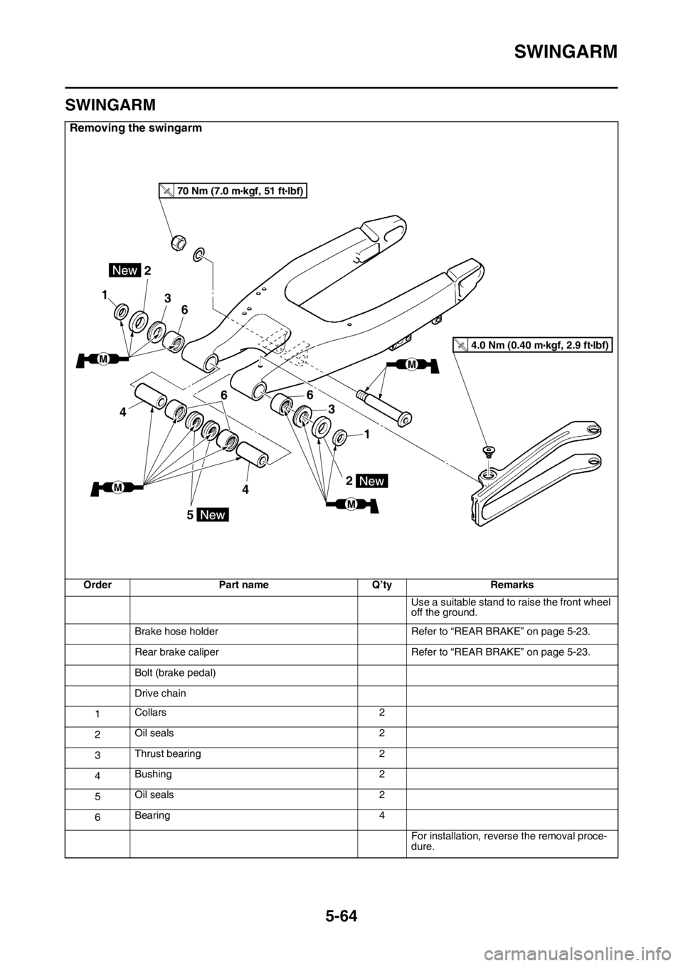
SWINGARM
Removing the swingarm
Order Part name Q’ty Remarks
Use a suitable stand to raise the front wheel
off the ground.
Brake hose holder Refer to “REAR BRAKE” on page 5-23.
Rear brake caliper Refer to “REAR BRAKE” on page 5-23.
Bolt (brake pedal)
Drive chain
1Collars 2
2Oil seals 2
3Thrust bearing 2
4Bushing 2
5Oil seals 2
6Bearing 4
For installation, reverse the removal proce-
dure.
1
2
3
6
4
6
4
1
3
6
2
5
T.R.70 Nm (7.0 mlbf) kgf, 51 ft
T.R.4.0 Nm (0.40 mlbf) kgf, 2.9 ft
Page 223 of 430
SWINGARM
5-65
EAS2GB2219REMOVING THE SWINGARM
1. Use a suitable stand to raise the rear wheel
off the ground.
EWA
WARNING
Securely support the vehicle so that there is
no danger of it falling over.
2. Measure:
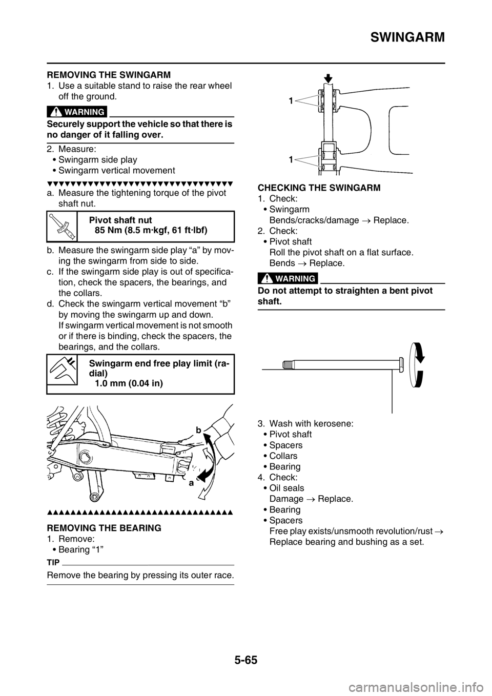
• Swingarm side play
• Swingarm vertical movement
▼▼▼▼▼▼▼▼▼▼▼▼▼▼▼▼▼▼▼▼▼▼▼▼▼▼▼▼▼▼▼▼
a. Measure the tightening torque of the pivot
shaft nut.
b. Measure the swingarm side play “a” by mov-
ing the swingarm from side to side.
c. If the swingarm side play is out of specifica-
tion, check the spacers, the bearings, and
the collars.
d. Check the swingarm vertical movement “b”
by moving the swingarm up and down.
If swingarm vertical movement is not smooth
or if there is binding, check the spacers, the
bearings, and the collars.
▲▲▲▲▲▲▲▲▲▲▲▲▲▲▲▲▲▲▲▲▲▲▲▲▲▲▲▲▲▲▲▲
EAS2GB2220REMOVING THE BEARING
1. Remove:
• Bearing “1”
TIP
Remove the bearing by pressing its outer race.
EAS2GB2221CHECKING THE SWINGARM
1. Check:
• Swingarm
Bends/cracks/damage Replace.
2. Check:
• Pivot shaft
Roll the pivot shaft on a flat surface.
Bends Replace.
EWA
WARNING
Do not attempt to straighten a bent pivot
shaft.
3. Wash with kerosene:
• Pivot shaft
• Spacers
•Collars
• Bearing
4. Check:
• Oil seals
Damage Replace.
• Bearing
• Spacers
Free play exists/unsmooth revolution/rust
Replace bearing and bushing as a set. Pivot shaft nut
85 Nm (8.5 m·kgf, 61 ft·lbf)
Swingarm end free play limit (ra-
dial)
1.0 mm (0.04 in)
T R..
Page 224 of 430
SWINGARM
5-66
EAS2GB2222INSTALLING THE SWINGARM
1. Lubricate:
• Bearing
•Collars
• Spacers
• Oil seal
• Pivot shaft
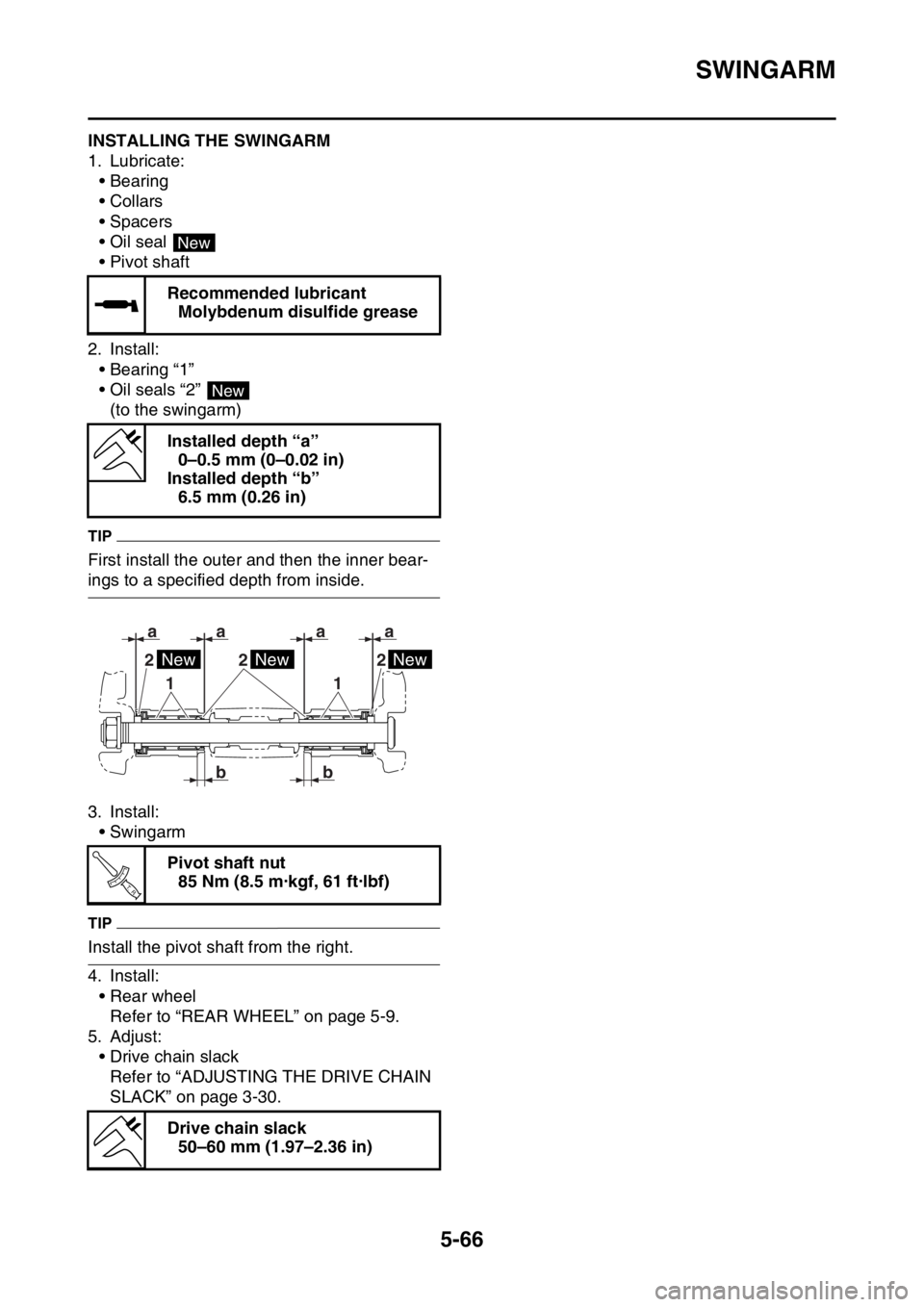
2. Install:
• Bearing “1”
• Oil seals “2”
(to the swingarm)
TIP
First install the outer and then the inner bear-
ings to a specified depth from inside.
3. Install:
• Swingarm
TIP
Install the pivot shaft from the right.
4. Install:
• Rear wheel
Refer to “REAR WHEEL” on page 5-9.
5. Adjust:
• Drive chain slack
Refer to “ADJUSTING THE DRIVE CHAIN
SLACK” on page 3-30.Recommended lubricant
Molybdenum disulfide grease
Installed depth “a”
0–0.5 mm (0–0.02 in)
Installed depth “b”
6.5 mm (0.26 in)
Pivot shaft nut
85 Nm (8.5 m·kgf, 61 ft·lbf)
Drive chain slack
50–60 mm (1.97–2.36 in)
New
New
2 22
1 1
aaa
b ba
NewNewNew
T R..
Page 225 of 430
CHAIN DRIVE
5-67
EAS2GB2223
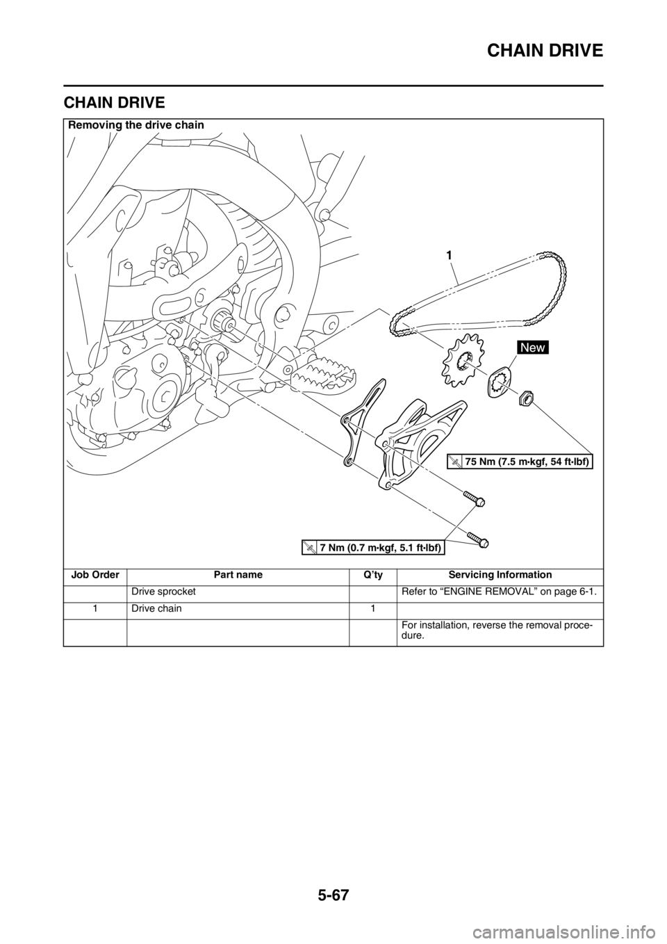
CHAIN DRIVE
Removing the drive chain
Job Order Part name Q’ty Servicing Information
Drive sprocket Refer to “ENGINE REMOVAL” on page 6-1.
1 Drive chain 1
For installation, reverse the removal proce-
dure.
1
T.R.75 Nm (7.5 mlbf) kgf, 54 ft
T.R.7 Nm (0.7 mlbf) kgf, 5.1 ft
Page 226 of 430
CHAIN DRIVE
5-68
EAS23420REMOVING THE DRIVE CHAIN
1. Stand the vehicle on a level surface.
EWA
WARNING
Securely support the vehicle so that there is
no danger of it falling over.
TIP
Place the vehicle on a suitable stand so that the
rear wheel is elevated.
2. Remove:
•Drive chain
TIP
Cut the drive chain with the drive chain cut &
rivet tool. (Use goods on the market)
EAS23441CHECKING THE DRIVE CHAIN
1. Measure:
• 15-link section of the drive chain
Out of specification Replace the drive
chain.
▼▼▼▼▼▼▼▼▼▼▼▼▼▼▼▼▼▼▼▼▼▼▼▼▼▼▼▼▼▼▼▼
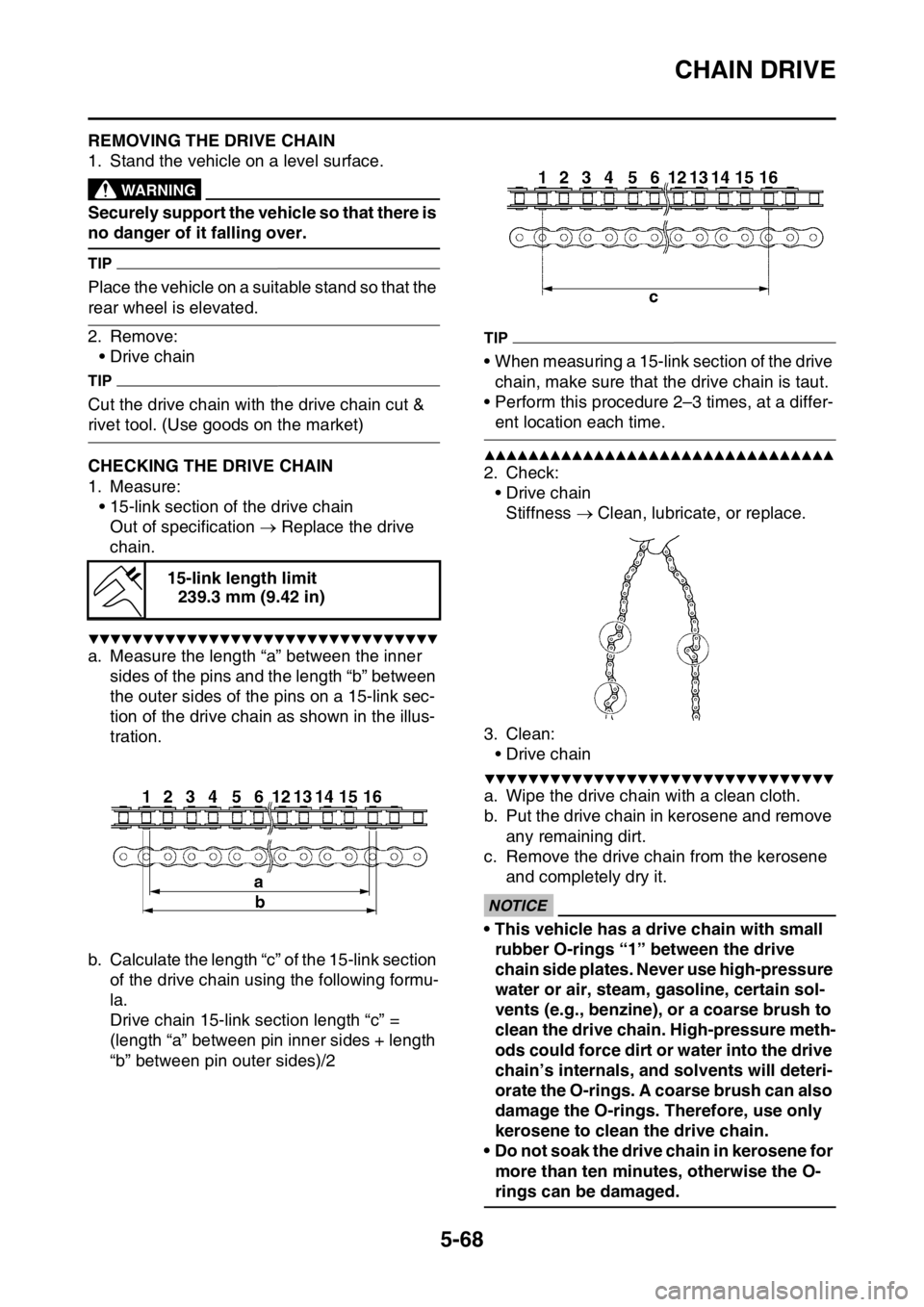
a. Measure the length “a” between the inner
sides of the pins and the length “b” between
the outer sides of the pins on a 15-link sec-
tion of the drive chain as shown in the illus-
tration.
b. Calculate the length “c” of the 15-link section
of the drive chain using the following formu-
la.
Drive chain 15-link section length “c” =
(length “a” between pin inner sides + length
“b” between pin outer sides)/2
TIP
• When measuring a 15-link section of the drive
chain, make sure that the drive chain is taut.
• Perform this procedure 2–3 times, at a differ-
ent location each time.
▲▲▲▲▲▲▲▲▲▲▲▲▲▲▲▲▲▲▲▲▲▲▲▲▲▲▲▲▲▲▲▲
2. Check:
•Drive chain
Stiffness Clean, lubricate, or replace.
3. Clean:
•Drive chain
▼▼▼▼▼▼▼▼▼▼▼▼▼▼▼▼▼▼▼▼▼▼▼▼▼▼▼▼▼▼▼▼
a. Wipe the drive chain with a clean cloth.
b. Put the drive chain in kerosene and remove
any remaining dirt.
c. Remove the drive chain from the kerosene
and completely dry it.
ECA
NOTICE
• This vehicle has a drive chain with small
rubber O-rings “1” between the drive
chain side plates. Never use high-pressure
water or air, steam, gasoline, certain sol-
vents (e.g., benzine), or a coarse brush to
clean the drive chain. High-pressure meth-
ods could force dirt or water into the drive
chain’s internals, and solvents will deteri-
orate the O-rings. A coarse brush can also
damage the O-rings. Therefore, use only
kerosene to clean the drive chain.
• Do not soak the drive chain in kerosene for
more than ten minutes, otherwise the O-
rings can be damaged. 15-link length limit
239.3 mm (9.42 in)
Page 227 of 430
CHAIN DRIVE
5-69
▲▲▲▲▲▲▲▲▲▲▲▲▲▲▲▲▲▲▲▲▲▲▲▲▲▲▲▲▲▲▲▲
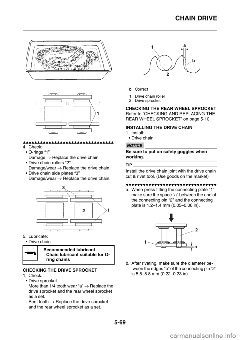
4. Check:
• O-rings “1”
Damage Replace the drive chain.
• Drive chain rollers “2”
Damage/wear Replace the drive chain.
• Drive chain side plates “3”
Damage/wear Replace the drive chain.
5. Lubricate:
•Drive chain
EAS2GB2224CHECKING THE DRIVE SPROCKET
1. Check:
• Drive sprocket
More than 1/4 tooth wear “a” Replace the
drive sprocket and the rear wheel sprocket
as a set.
Bent tooth Replace the drive sprocket
and the rear wheel sprocket as a set.
EAS2GB2225CHECKING THE REAR WHEEL SPROCKET
Refer to “CHECKING AND REPLACING THE
REAR WHEEL SPROCKET” on page 5-10.
EAS2GB2226INSTALLING THE DRIVE CHAIN
1. Install:
•Drive chain
ECA
NOTICE
Be sure to put on safety goggles when
working.
TIP
Install the drive chain joint with the drive chain
cut & rivet tool. (Use goods on the market)
▼▼▼▼▼▼▼▼▼▼▼▼▼▼▼▼▼▼▼▼▼▼▼▼▼▼▼▼▼▼▼▼
a. When press fitting the connecting plate “1”,
make sure the space “a” between the end of
the connecting pin “2” and the connecting
plate is 1.2–1.4 mm (0.05–0.06 in).
b. After riveting, make sure the diameter be-
tween the edges “b” of the connecting pin “2”
is 5.5–5.8 mm (0.22–0.23 in). Recommended lubricant
Chain lubricant suitable for O-
ring chains
b. Correct
1. Drive chain roller
2. Drive sprocket
Page 228 of 430
CHAIN DRIVE
5-70
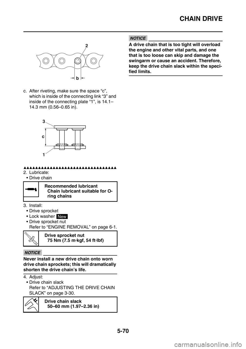
c. After riveting, make sure the space “c”,
which is inside of the connecting link “3” and
inside of the connecting plate “1”, is 14.1–
14.3 mm (0.56–0.65 in).
▲▲▲▲▲▲▲▲▲▲▲▲▲▲▲▲▲▲▲▲▲▲▲▲▲▲▲▲▲▲▲▲
2. Lubricate:
•Drive chain
3. Install:
• Drive sprocket
• Lock washer
• Drive sprocket nut
Refer to “ENGINE REMOVAL” on page 6-1.
ECA
NOTICE
Never install a new drive chain onto worn
drive chain sprockets; this will dramatically
shorten the drive chain’s life.
4. Adjust:
• Drive chain slack
Refer to “ADJUSTING THE DRIVE CHAIN
SLACK” on page 3-30.
ECA
NOTICE
A drive chain that is too tight will overload
the engine and other vital parts, and one
that is too loose can skip and damage the
swingarm or cause an accident. Therefore,
keep the drive chain slack within the speci-
fied limits.
Recommended lubricant
Chain lubricant suitable for O-
ring chains
Drive sprocket nut
75 Nm (7.5 m·kgf, 54 ft·lbf)
Drive chain slack
50–60 mm (1.97–2.36 in)
New
T R..
Page 229 of 430

6
ENGINE
ENGINE REMOVAL......................................................................................... 6-1
REMOVING THE SILENCER ..................................................................... 6-6
REMOVING THE EXHAUST PIPE 2.......................................................... 6-6
REMOVING THE DRIVE SPROCKET ....................................................... 6-6
REMOVING THE ENGINE ......................................................................... 6-7
CLEANING THE SPARK ARRESTER ....................................................... 6-7
CHECKING THE SILENCER AND EXHAUST PIPE.................................. 6-8
INSTALLING THE ENGINE........................................................................ 6-8
INSTALLING THE BRAKE PEDAL ............................................................ 6-9
INSTALLING THE DRIVE SPROCKET...................................................... 6-9
INSTALLING THE EXHAUST PIPE AND MUFFLER................................. 6-9
CAMSHAFT.................................................................................................... 6-11
REMOVING THE CAMSHAFT ................................................................. 6-13
CHECKING THE CAMSHAFT.................................................................. 6-14
CHECKING THE TIMING CHAIN AND CAMSHAFT SPROCKET .......... 6-15
CHECKING THE TIMING CHAIN TENSIONERS .................................... 6-15
CHECKING THE DECOMPRESSION SYSTEM...................................... 6-16
INSTALLING THE CAMSHAFTS ............................................................. 6-16
CYLINDER HEAD........................................................................................... 6-18
REMOVING THE CYLINDER HEAD........................................................ 6-20
CHECKING THE TIMING CHAIN GUIDE (INTAKE SIDE) ...................... 6-20
CHECKING THE CYLINDER HEAD ........................................................ 6-20
INSTALLING THE CYLINDER HEAD ...................................................... 6-21
VALVES AND VALVE SPRINGS................................................................... 6-22
REMOVING THE VALVES ....................................................................... 6-23
CHECKING THE VALVES AND VALVE GUIDES ................................... 6-24
CHECKING THE VALVE SEATS ............................................................. 6-26
CHECKING THE VALVE SPRINGS......................................................... 6-27
CHECKING THE VALVE LIFTERS .......................................................... 6-28
INSTALLING THE VALVES ..................................................................... 6-28
CYLINDER AND PISTON............................................................................... 6-30
REMOVING THE PISTON ....................................................................... 6-31
CHECKING THE CYLINDER AND PISTON ............................................ 6-31
CHECKING THE PISTON RINGS............................................................ 6-32
CHECKING THE PISTON PIN ................................................................. 6-33
INSTALLING THE PISTON AND CYLINDER .......................................... 6-33
ELECTRIC STARTER.................................................................................... 6-35
CHECKING THE STARTER MOTOR ...................................................... 6-37
ASSEMBLING THE STARTER MOTOR .................................................. 6-38
Page 230 of 430

CLUTCH......................................................................................................... 6-40
REMOVING THE CLUTCH ...................................................................... 6-43
CHECKING THE FRICTION PLATES...................................................... 6-43
CHECKING THE CLUTCH PLATES ........................................................ 6-43
CHECKING THE CLUTCH SPRINGS...................................................... 6-43
CHECKING THE CLUTCH HOUSING ..................................................... 6-44
CHECKING THE CLUTCH BOSS ............................................................ 6-44
CHECKING THE PRESSURE PLATE ..................................................... 6-44
CHECKING THE PUSH LEVER SHAFT .................................................. 6-44
CHECKING THE CLUTCH PUSH RODS ................................................ 6-44
CHECKING THE PRIMARY DRIVE GEAR .............................................. 6-44
CHECKING THE PRIMARY DRIVEN GEAR ........................................... 6-45
INSTALLING THE OIL SEAL................................................................... 6-45
INSTALLING THE RIGHT CRANKCASE COVER ................................... 6-45
INSTALLING THE CLUTCH ..................................................................... 6-45
INSTALLING THE KICKSTARTER LEVER ............................................. 6-48
KICKSTATER................................................................................................. 6-49
REMOVING THE KICK SHAFT ASSEMBLY ........................................... 6-50
CHECKING THE KICK SHAFT AND RATCHET WHEEL ........................ 6-50
CHECKING THE KICK GEAR, KICK IDLE GEAR AND RATCHET
WHEEL .................................................................................................... 6-50
INSTALLING THE KICK SHAFT ASSEMBLY .......................................... 6-50
INSTALLING THE KICK IDLE GEAR ....................................................... 6-51
SHIFT SHAFT................................................................................................. 6-52
REMOVING THE SHIFT GUIDE AND SHIFT LEVER ASSEMBLY ......... 6-53
REMOVING THE SEGMENT ................................................................... 6-53
CHECKING THE SHIFT SHAFT .............................................................. 6-53
CHECKING THE SHIFT GUIDE AND SHIFT LEVER ASSEMBLY ......... 6-53
CHECKING THE STOPPER LEVER ....................................................... 6-53
INSTALLING THE STOPPER LEVER ..................................................... 6-54
INSTALLING THE SEGMENT.................................................................. 6-54
INSTALLING THE SHIFT GUIDE AND SHIFT LEVER ASSEMBLY ....... 6-54
INSTALLING THE SHIFT SHAFT ............................................................ 6-55
INSTALLING THE SHIFT PEDAL ............................................................ 6-55
OIL PUMP AND BALANCER GEAR............................................................. 6-56
REMOVING THE BALANCER ................................................................. 6-58
CHECKING THE PRIMARY DRIVE GEAR, BALANCER SHAFT DRIVE
GEAR, AND BALANCER WEIGHT GEAR .............................................. 6-58
CHECKING THE BALANCER .................................................................. 6-58
CHECKING THE OIL PUMP .................................................................... 6-58
ASSEMBLING THE OIL PUMP ................................................................ 6-59
INSTALLING THE OIL PUMP AND BALANCER GEAR .......................... 6-59