YAMAHA WR 250F 2015 Owner's Guide
Manufacturer: YAMAHA, Model Year: 2015, Model line: WR 250F, Model: YAMAHA WR 250F 2015Pages: 430, PDF Size: 14.14 MB
Page 31 of 430
SPECIAL TOOLS
1-17
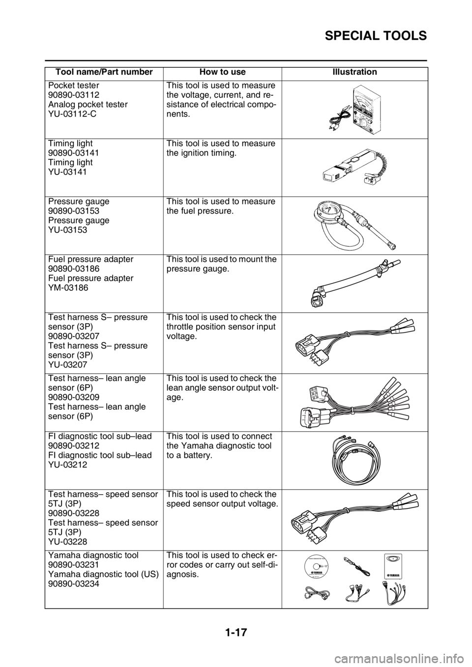
Pocket tester
90890-03112
Analog pocket tester
YU-03112-CThis tool is used to measure
the voltage, current, and re-
sistance of electrical compo-
nents.
Timing light
90890-03141
Timing light
YU-03141This tool is used to measure
the ignition timing.
Pressure gauge
90890-03153
Pressure gauge
YU-03153This tool is used to measure
the fuel pressure.
Fuel pressure adapter
90890-03186
Fuel pressure adapter
YM-03186This tool is used to mount the
pressure gauge.
Test harness S– pressure
sensor (3P)
90890-03207
Test harness S– pressure
sensor (3P)
YU-03207This tool is used to check the
throttle position sensor input
voltage.
Test harness– lean angle
sensor (6P)
90890-03209
Test harness– lean angle
sensor (6P)This tool is used to check the
lean angle sensor output volt-
age.
FI diagnostic tool sub–lead
90890-03212
FI diagnostic tool sub–lead
YU-03212This tool is used to connect
the Yamaha diagnostic tool
to a battery.
Test harness– speed sensor
5TJ (3P)
90890-03228
Test harness– speed sensor
5TJ (3P)
YU-03228This tool is used to check the
speed sensor output voltage.
Yamaha diagnostic tool
90890-03231
Yamaha diagnostic tool (US)
90890-03234This tool is used to check er-
ror codes or carry out self-di-
agnosis. Tool name/Part number How to use Illustration
Page 32 of 430
SPECIAL TOOLS
1-18
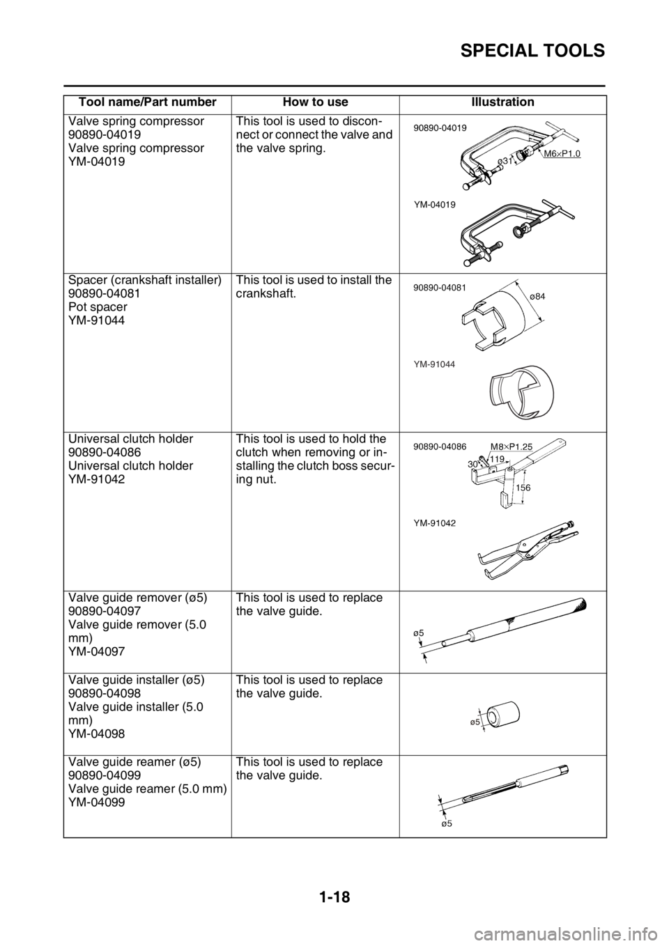
Valve spring compressor
90890-04019
Valve spring compressor
YM-04019This tool is used to discon-
nect or connect the valve and
the valve spring.
Spacer (crankshaft installer)
90890-04081
Pot spacer
YM-91044This tool is used to install the
crankshaft.
Universal clutch holder
90890-04086
Universal clutch holder
YM-91042This tool is used to hold the
clutch when removing or in-
stalling the clutch boss secur-
ing nut.
Valve guide remover (ø5)
90890-04097
Valve guide remover (5.0
mm)
YM-04097This tool is used to replace
the valve guide.
Valve guide installer (ø5)
90890-04098
Valve guide installer (5.0
mm)
YM-04098This tool is used to replace
the valve guide.
Valve guide reamer (ø5)
90890-04099
Valve guide reamer (5.0 mm)
YM-04099This tool is used to replace
the valve guide. Tool name/Part number How to use Illustration
YM-04019
YM-91044
Page 33 of 430
SPECIAL TOOLS
1-19
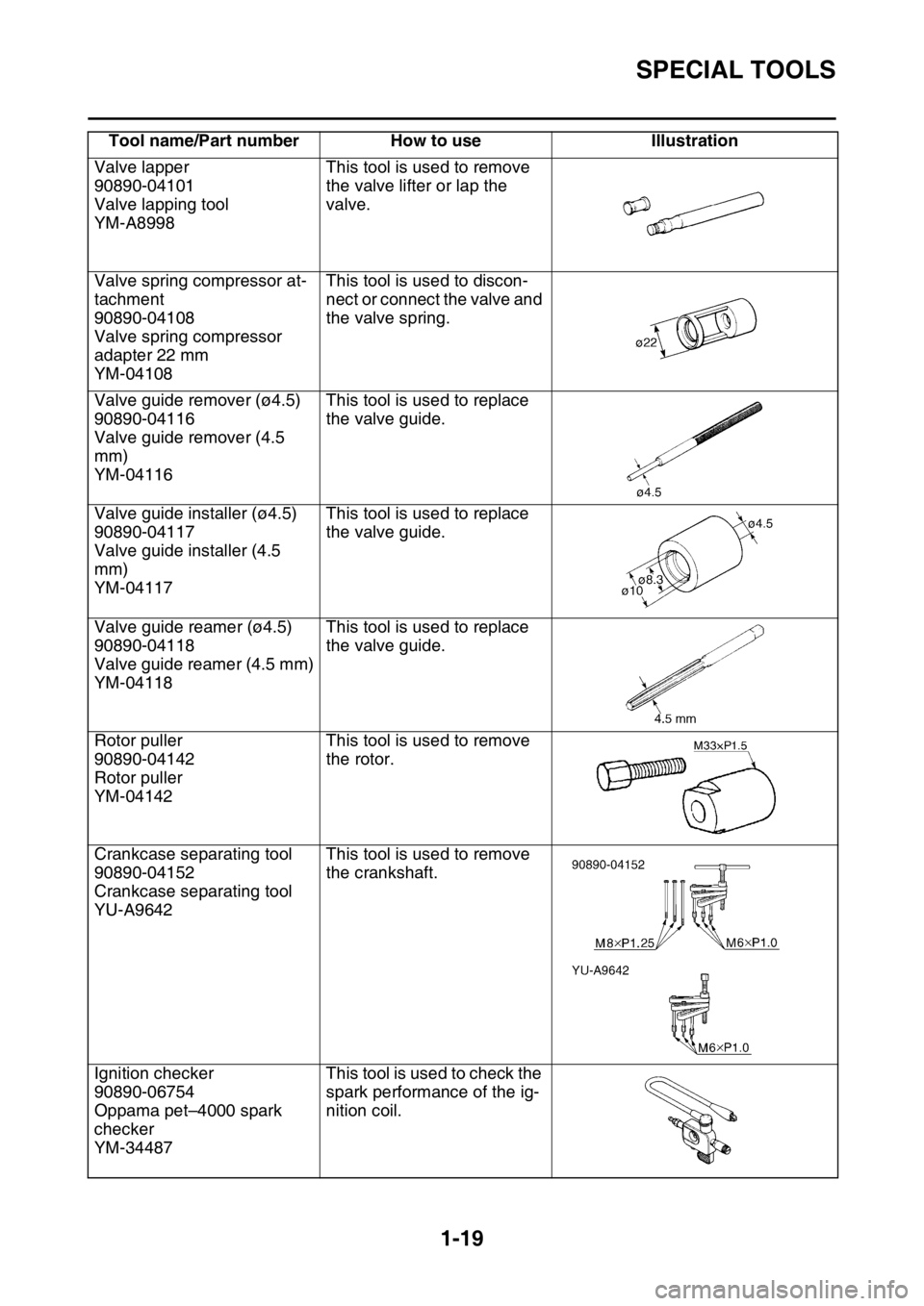
Valve lapper
90890-04101
Valve lapping tool
YM-A8998This tool is used to remove
the valve lifter or lap the
valve.
Valve spring compressor at-
tachment
90890-04108
Valve spring compressor
adapter 22 mm
YM-04108This tool is used to discon-
nect or connect the valve and
the valve spring.
Valve guide remover (ø4.5)
90890-04116
Valve guide remover (4.5
mm)
YM-04116This tool is used to replace
the valve guide.
Valve guide installer (ø4.5)
90890-04117
Valve guide installer (4.5
mm)
YM-04117This tool is used to replace
the valve guide.
Valve guide reamer (ø4.5)
90890-04118
Valve guide reamer (4.5 mm)
YM-04118This tool is used to replace
the valve guide.
Rotor puller
90890-04142
Rotor puller
YM-04142This tool is used to remove
the rotor.
Crankcase separating tool
90890-04152
Crankcase separating tool
YU-A9642This tool is used to remove
the crankshaft.
Ignition checker
90890-06754
Oppama pet–4000 spark
checker
YM-34487This tool is used to check the
spark performance of the ig-
nition coil. Tool name/Part number How to use Illustration
Page 34 of 430

SPECIAL TOOLS
1-20
Digital tachometer
90890-06760
Digital tachometer
YU-39951-BThis tool is used to measure
the engine speed.
Yamaha bond No. 1215
90890-85505
(Three bond No.1215®)This sealant (Bond) is used
for crankcase mating sur-
face, etc. Tool name/Part number How to use Illustration
Page 35 of 430

CONTROL FUNCTIONS
1-21
EAS2GB2031
CONTROL FUNCTIONS
EAS2GB2032INDICATOR LIGHTS AND WARNING
LIGHTS
1. Engine trouble warning light “ ”
2. Fuel level warning light “ ”
Fuel level warning light “ ”
This warning light comes on when the fuel level
drops below approximately 1.6 L (0.42 US gal,
0.35 Imp.gal). When this occurs, refuel as soon
as possible.
The electrical circuit of the warning light can be
checked by pushing the start switch. The warn-
ing light should come on for a few seconds, and
then go off.
If the warning light does not come on initially
when the start switch is pushed, or if the warn-
ing light remains on, have a Yamaha dealer
check the electrical circuit.
Engine trouble warning light “ ”
This warning light comes on or flashes if a prob-
lem is detected in the electrical circuit monitor-
ing the engine. If this occurs, have a Yamaha
dealer check the vehicle.
The electrical circuit of the warning light can be
checked by pushing the start switch. The warn-
ing light should come on for a few seconds, and
then go off.
If the warning light does not come on initially
when the start switch is pushed, or if the warn-
ing light remains on, have a Yamaha dealer
check the electrical circuit.
EAS2GB2033ENGINE STOP SWITCH
The engine stop switch “1” is located on the left
handlebar. Continue pushing the engine stop
switch till the engine comes to a stop.
After the engine stops, the multi-function dis-
play will go off and the power supply to the ECU
(Electronic Control Unit) will be cut off if the en-
gine stop switch is pushed and held.
TIP
The multi-function display will go off after one
minute if the engine stop switch is not pushed.
EAS2GB2034START SWITCH
The start switch “1” is located on the right han-
dlebar. Push this switch to crank the engine
with the starter.
EAS2GB2035CLUTCH LEVER
The clutch lever “1” is located on the left han-
dlebar. The clutch lever disengages or engag-
es the clutch.
Pull the clutch lever toward the handlebar to
disengage the clutch, and release the lever to
engage the clutch.
12
Page 36 of 430
CONTROL FUNCTIONS
1-22
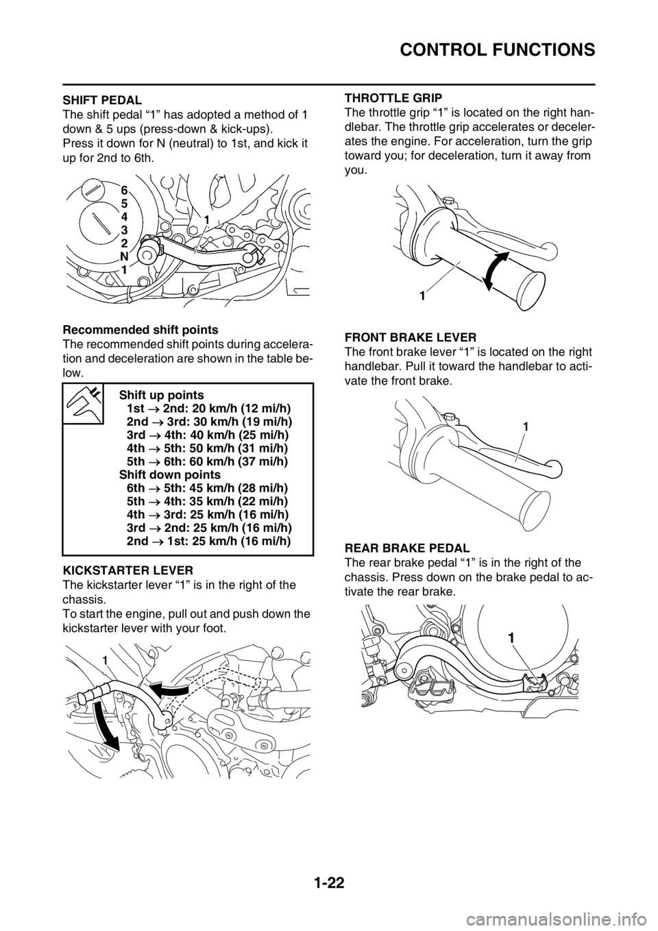
EAS2GB2036SHIFT PEDAL
The shift pedal “1” has adopted a method of 1
down & 5 ups (press-down & kick-ups).
Press it down for N (neutral) to 1st, and kick it
up for 2nd to 6th.
Recommended shift points
The recommended shift points during accelera-
tion and deceleration are shown in the table be-
low.
EAS2GB2037KICKSTARTER LEVER
The kickstarter lever “1” is in the right of the
chassis.
To start the engine, pull out and push down the
kickstarter lever with your foot.
EAS2GB2038
THROTTLE GRIP
The throttle grip “1” is located on the right han-
dlebar. The throttle grip accelerates or deceler-
ates the engine. For acceleration, turn the grip
toward you; for deceleration, turn it away from
you.
EAS2GB2039FRONT BRAKE LEVER
The front brake lever “1” is located on the right
handlebar. Pull it toward the handlebar to acti-
vate the front brake.
EAS2GB2040REAR BRAKE PEDAL
The rear brake pedal “1” is in the right of the
chassis. Press down on the brake pedal to ac-
tivate the rear brake. Shift up points
1st 2nd: 20 km/h (12 mi/h)
2nd 3rd: 30 km/h (19 mi/h)
3rd 4th: 40 km/h (25 mi/h)
4th 5th: 50 km/h (31 mi/h)
5th 6th: 60 km/h (37 mi/h)
Shift down points
6th 5th: 45 km/h (28 mi/h)
5th 4th: 35 km/h (22 mi/h)
4th 3rd: 25 km/h (16 mi/h)
3rd 2nd: 25 km/h (16 mi/h)
2nd 1st: 25 km/h (16 mi/h)
1
1
1
Page 37 of 430
CONTROL FUNCTIONS
1-23
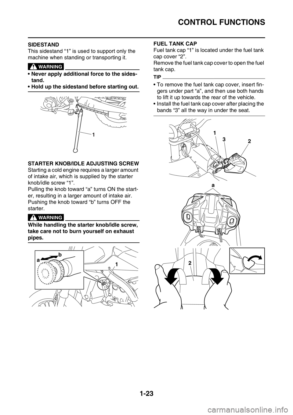
EAS2GB2041SIDESTAND
This sidestand “1” is used to support only the
machine when standing or transporting it.
EWA
WARNING
• Never apply additional force to the sides-
tand.
• Hold up the sidestand before starting out.
EAS2GB2042STARTER KNOB/IDLE ADJUSTING SCREW
Starting a cold engine requires a larger amount
of intake air, which is supplied by the starter
knob/idle screw “1”.
Pulling the knob toward “a” turns ON the start-
er, resulting in a larger amount of intake air.
Pushing the knob toward “b” turns OFF the
starter.
EWA
WARNING
While handling the starter knob/idle screw,
take care not to burn yourself on exhaust
pipes.
EAS2GB2043
FUEL TANK CAP
Fuel tank cap “1” is located under the fuel tank
cap cover “2”.
Remove the fuel tank cap cover to open the fuel
tank cap.
TIP
• To remove the fuel tank cap cover, insert fin-
gers under part “a”, and then use both hands
to lift it up towards the rear of the vehicle.
• Install the fuel tank cap cover after placing the
bands “3” all the way in under the seat.
1
ab1
1
23
a
2
Page 38 of 430
MULTI-FUNCTION DISPLAY
1-24
EAS2GB2044
MULTI-FUNCTION DISPLAYEWA
WARNING
Be sure to stop the machine before making
any setting changes to the multi-function
display.
The multi-function display is equipped with the
following:
BASIC MODE:
• Speedometer
•Clock
• Two tripmeters (which shows the distance
that has been traveled since it was last set to
zero)
RACE MODE:
• Timer (which shows the time that has been
accumulated since the start of timer measure-
ment)
• Tripmeter (which shows the accumulated
travel distance in timer measurement)
• Change tripmeter digits (capable of change to
any given ones)
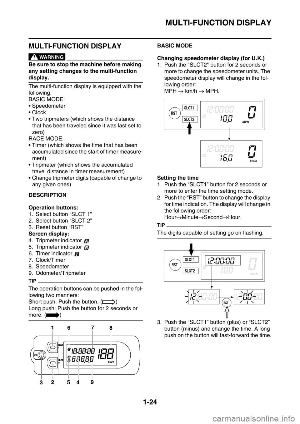
EAS2GB2045DESCRIPTION
Operation buttons:
1. Select button “SLCT 1”
2. Select button “SLCT 2”
3. Reset button “RST”
Screen display:
4. Tripmeter indicator
5. Tripmeter indicator
6. Timer indicator
7. Clock/Timer
8. Speedometer
9. Odometer/Tripmeter
TIP
The operation buttons can be pushed in the fol-
lowing two manners:
Short push: Push the button. ( )
Long push: Push the button for 2 seconds or
more. ( )
EAS2GB2046BASIC MODE
Changing speedometer display (for U.K.)
1. Push the "SLCT2" button for 2 seconds or
more to change the speedometer units. The
speedometer display will change in the fol-
lowing order:
MPH km/h MPH.
Setting the time
1. Push the “SLCT1” button for 2 seconds or
more to enter the time setting mode.
2. Push the “RST” button to change the display
for time indication. The display will change in
the following order:
HourMinuteSecondHour.
TIP
The digits capable of setting go on flashing.
3. Push the “SLCT1” button (plus) or “SLCT2”
button (minus) and change the time. A long
push on the button will fast-forward the time.
Page 39 of 430
MULTI-FUNCTION DISPLAY
1-25
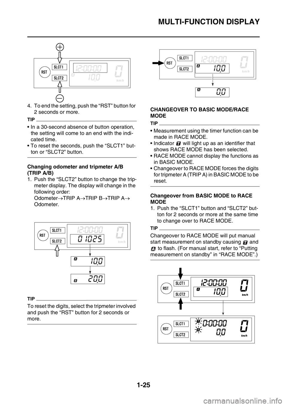
4. To end the setting, push the “RST” button for
2 seconds or more.
TIP
• In a 30-second absence of button operation,
the setting will come to an end with the indi-
cated time.
• To reset the seconds, push the “SLCT1” but-
ton or “SLCT2” button.
Changing odometer and tripmeter A/B
(TRIP A/B)
1. Push the “SLCT2” button to change the trip-
meter display. The display will change in the
following order:
OdometerTRIP ATRIP BTRIP A
Odometer.
TIP
To reset the digits, select the tripmeter involved
and push the “RST” button for 2 seconds or
more.
EAS2GB2047CHANGEOVER TO BASIC MODE/RACE
MODE
TIP
• Measurement using the timer function can be
made in RACE MODE.
• Indicator will light up as an identifier that
shows RACE MODE has been selected.
• RACE MODE cannot display the functions as
in BASIC MODE.
• Changeover to RACE MODE forces the digits
for tripmeter A (TRIP A) in BASIC MODE to be
reset.
Changeover from BASIC MODE to RACE
MODE
1. Push the “SLCT1” button and “SLCT2” but-
ton for 2 seconds or more at the same time
to change over to RACE MODE.
TIP
Changeover to RACE MODE will put manual
start measurement on standby causing and
to flash. (For manual start, refer to “Putting
measurement on standby” in “RACE MODE”.)
Page 40 of 430
MULTI-FUNCTION DISPLAY
1-26
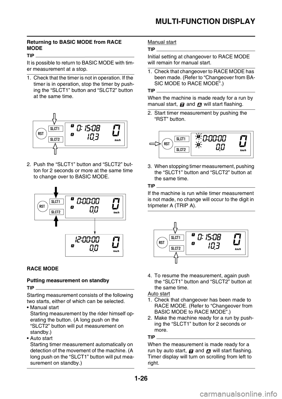
Returning to BASIC MODE from RACE
MODE
TIP
It is possible to return to BASIC MODE with tim-
er measurement at a stop.
1. Check that the timer is not in operation. If the
timer is in operation, stop the timer by push-
ing the “SLCT1” button and “SLCT2” button
at the same time.
2. Push the “SLCT1” button and “SLCT2” but-
ton for 2 seconds or more at the same time
to change over to BASIC MODE.
EAS2GB2048RACE MODE
Putting measurement on standby
TIP
Starting measurement consists of the following
two starts, either of which can be selected.
• Manual start
Starting measurement by the rider himself op-
erating the button. (A long push on the
“SLCT2” button will put measurement on
standby.)
• Auto start
Starting timer measurement automatically on
detection of the movement of the machine. (A
long push on the “SLCT1” button will put mea-
surement on standby.)Manual start
TIP
Initial setting at changeover to RACE MODE
will remain for manual start.
1. Check that changeover to RACE MODE has
been made. (Refer to “Changeover from BA-
SIC MODE to RACE MODE”.)
TIP
When the machine is made ready for a run by
manual start, and will start flashing.
2. Start timer measurement by pushing the
“RST” button.
3. When stopping timer measurement, pushing
the “SLCT1” button and “SLCT2” button at
the same time.
TIP
If the machine is run while timer measurement
is not made, no change will occur to the digit in
tripmeter A (TRIP A).
4. To resume the measurement, again push
the “SLCT1” button and “SLCT2” button at
the same time.
Auto start
1. Check that changeover has been made to
RACE MODE. (Refer to “Changeover from
BASIC MODE to RACE MODE”.)
2. Make the machine ready for a run by push-
ing the “SLCT1” button for 2 seconds or
more.
TIP
When the measurement is made ready for a
run by auto start, and will start flashing.
Timer display will turn on scrolling from left to
right.