air filter YAMAHA WR 250F 2015 Owners Manual
[x] Cancel search | Manufacturer: YAMAHA, Model Year: 2015, Model line: WR 250F, Model: YAMAHA WR 250F 2015Pages: 430, PDF Size: 14.14 MB
Page 14 of 430

CONTROL FUNCTIONS................................................................................ 1-21
INDICATOR LIGHTS AND WARNING LIGHTS ....................................... 1-21
ENGINE STOP SWITCH .......................................................................... 1-21
START SWITCH....................................................................................... 1-21
CLUTCH LEVER...................................................................................... 1-21
SHIFT PEDAL .......................................................................................... 1-22
KICKSTARTER LEVER............................................................................ 1-22
THROTTLE GRIP ..................................................................................... 1-22
FRONT BRAKE LEVER ........................................................................... 1-22
REAR BRAKE PEDAL.............................................................................. 1-22
SIDESTAND ............................................................................................. 1-23
STARTER KNOB/IDLE ADJUSTING SCREW ......................................... 1-23
FUEL TANK CAP ..................................................................................... 1-23
MULTI-FUNCTION DISPLAY......................................................................... 1-24
DESCRIPTION ......................................................................................... 1-24
BASIC MODE ........................................................................................... 1-24
CHANGEOVER TO BASIC MODE/RACE MODE.................................... 1-25
RACE MODE ............................................................................................ 1-26
FUNCTION DIAGRAM ............................................................................. 1-30
STARTING AND BREAK-IN.......................................................................... 1-32
FUEL ........................................................................................................ 1-32
HANDLING NOTE .................................................................................... 1-32
AIR FILTER MAINTENANCE ................................................................... 1-32
STARTING A COLD ENGINE .................................................................. 1-32
STARTING A WARM ENGINE ................................................................. 1-33
BREAK-IN PROCEDURES ...................................................................... 1-34
MAINTENANCE AFTER BREAK-IN.............................................................. 1-35
MAJOR MAINTENANCE .......................................................................... 1-35
TORQUE-CHECK POINTS............................................................................ 1-36
MOTORCYCLE CARE AND STORAGE........................................................ 1-38
CARE........................................................................................................ 1-38
STORAGE ................................................................................................ 1-39
Page 18 of 430

DESCRIPTION
1-4
EAS2GB2009
DESCRIPTION
TIP
Designs and specifications of the vehicle are subject to change without notice. Therefore, please
note that the descriptions in this manual may be different from those for the vehicle you have pur-
chased.1. Clutch lever 12. Headlight
2. Multi-function display 13. Radiator
3. Front brake lever 14. Coolant drain bolt
4. Throttle grip 15. Rear brake pedal
5. Start switch 16. Air filter
6. Radiator cap 17. Drive chain
7. Fuel tank cap 18. Shift pedal
8. Engine stop switch 19. Oil level check window
9. Taillight 20. Starter knob/idle screw
10. Fuel tank 21. Front fork
11. Kickstarter lever
32 1
8
10
91112 1376
54
15 14 21 20 19 18 1716
Page 21 of 430
FEATURES
1-7
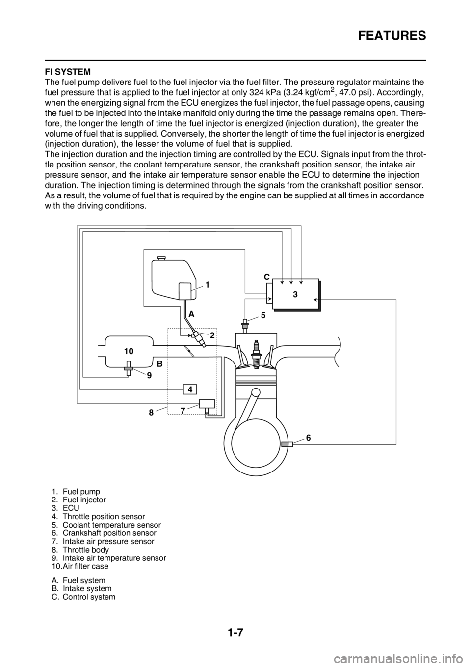
EAS2GB2015FI SYSTEM
The fuel pump delivers fuel to the fuel injector via the fuel filter. The pressure regulator maintains the
fuel pressure that is applied to the fuel injector at only 324 kPa (3.24 kgf/cm
2, 47.0 psi). Accordingly,
when the energizing signal from the ECU energizes the fuel injector, the fuel passage opens, causing
the fuel to be injected into the intake manifold only during the time the passage remains open. There-
fore, the longer the length of time the fuel injector is energized (injection duration), the greater the
volume of fuel that is supplied. Conversely, the shorter the length of time the fuel injector is energized
(injection duration), the lesser the volume of fuel that is supplied.
The injection duration and the injection timing are controlled by the ECU. Signals input from the throt-
tle position sensor, the coolant temperature sensor, the crankshaft position sensor, the intake air
pressure sensor, and the intake air temperature sensor enable the ECU to determine the injection
duration. The injection timing is determined through the signals from the crankshaft position sensor.
As a result, the volume of fuel that is required by the engine can be supplied at all times in accordance
with the driving conditions.
1. Fuel pump
2. Fuel injector
3. ECU
4. Throttle position sensor
5. Coolant temperature sensor
6. Crankshaft position sensor
7. Intake air pressure sensor
8. Throttle body
9. Intake air temperature sensor
10.Air filter case
A. Fuel system
B. Intake system
C. Control system
1
23
5
6 7
8 9 10A
BC
4
Page 46 of 430
STARTING AND BREAK-IN
1-32
EAS2GB2050
STARTING AND BREAK-IN
EAS2GB2051FUEL
Always use the recommended fuel as stated
below. Also, be sure to use new gasoline the
day of a race.
ECA
NOTICE
Use only unleaded gasoline. The use of
leaded gasoline will cause severe damage
to the engine internal parts such as valves,
piston rings, and exhaust system, etc.
TIP
Your Yamaha engine has been designed to use
premium unleaded gasoline with a pump oc-
tane number [(R+M)/2] of 91 or higher, or a re-
search octane number of 95 or higher. If
knocking (or pinging) occurs, use a gasoline of
a different brand.
EWA
WARNING
• For refueling, be sure to stop the engine
and use enough care not to spill any fuel.
Also be sure to avoid refueling close to a
fire.
• Refuel after the engine, exhaust pipe, etc.
have cooled off.
Gasohol (For USA and Canada)
There are two types of gasohol: gasohol con-
taining ethanol and that containing methanol.
Gasohol containing ethanol can be used if the
ethanol content does not exceed 10%. Gasohol
containing methanol is not recommended by
Yamaha because it can cause damage to the
fuel system or vehicle performance problems.
EAS2GB2052HANDLING NOTEEWA
WARNING
Never start or run the engine in a closed ar-
ea. The exhaust fumes are poisonous; they
can cause loss of consciousness and death
in a very short time. Always operate the ma-
chine in a well-ventilated area.
ECA
NOTICE
• Unlike a two-stroke engine, this engine
cannot be kick started when the throttle is
open because the kickstarter may kick
back. Also, if the throttle is open the air/
fuel mixture may be too lean for the engine
to start.
• Before starting the machine, perform the
checks in the pre-operation check list.
EAS2GB2053AIR FILTER MAINTENANCE
According to “CLEANING THE AIR FILTER
ELEMENT” section in the CHAPTER 3, apply
the foam-air-filter oil or its equivalent to the ele-
ment. (Excess oil in the element may adversely
affect engine starting.)
EAS2GB2054STARTING A COLD ENGINEECA
NOTICE
For maximum engine life, never accelerate
hard when the engine is cold!
In order for the ignition circuit cut-off system to
enable starting, one of the following conditions
must be met:
• The transmission is in the neutral position.
• The transmission is in gear with the clutch le-
ver pulled.
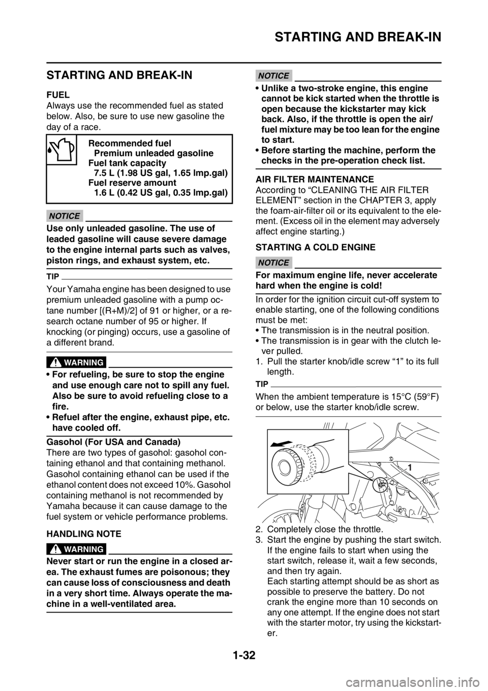
1. Pull the starter knob/idle screw “1” to its full
length.
TIP
When the ambient temperature is 15°C (59°F)
or below, use the starter knob/idle screw.
2. Completely close the throttle.
3. Start the engine by pushing the start switch.
If the engine fails to start when using the
start switch, release it, wait a few seconds,
and then try again.
Each starting attempt should be as short as
possible to preserve the battery. Do not
crank the engine more than 10 seconds on
any one attempt. If the engine does not start
with the starter motor, try using the kickstart-
er. Recommended fuel
Premium unleaded gasoline
Fuel tank capacity
7.5 L (1.98 US gal, 1.65 lmp.gal)
Fuel reserve amount
1.6 L (0.42 US gal, 0.35 lmp.gal)
1
Page 48 of 430
STARTING AND BREAK-IN
1-34
EAS2GB2056BREAK-IN PROCEDURES
A break-in is important so that rotating portion,
sliding surfaces, and mounted areas may fit
one another, and that the rider may become ac-
customed to the machine.
ECA
NOTICE
Before running, do maintenance on the air
filter element.
Refer to “CLEANING THE AIR FILTER ELE-
MENT” on page 3-14.
1. After warming up the engine, drive it for
about 20 minutes at a throttle opening of 1/2
or less.
2. Make a pit stop, and check mounted areas
for looseness, oil leaks, or other problems.
3. Then, drive it for about 40 minutes at a throt-
tle opening of 3/4 or less.
4. Make a pit stop again, and thoroughly check
mounted areas for looseness, oil leaks, or
other problems. Thorough checks and ad-
justments are required in particular for
stretch of cables, free play of the brake,
stretch of the drive chain, looseness of the
spoke, and so on.
ECA
NOTICE
After a break-in or after each race, always
check the points shown in “TORQUE-
CHECK POINTS” for tightening torques and
retighten them. (Refer to “TORQUE-CHECK
POINTS” on page 1-36.)
Also when the following parts are replaced,
a break-in is required.
• Cylinder and Crankshaft: A break-in is re-
quired for about an hour.
• Piston, Piston ring, Valve, Camshaft, and
Gear: A break-in is required for about 30
minutes at a throttle opening of 1/2 or less.
Observe the condition of the engine careful-
ly during a break-in.
For checkpoints for a break-in, see “MAIN-
TENANCE AFTER BREAK-IN”. If any prob-
lem is found, immediately stop the engine
and make a checkup.
Page 61 of 430
ENGINE SPECIFICATIONS
2-6
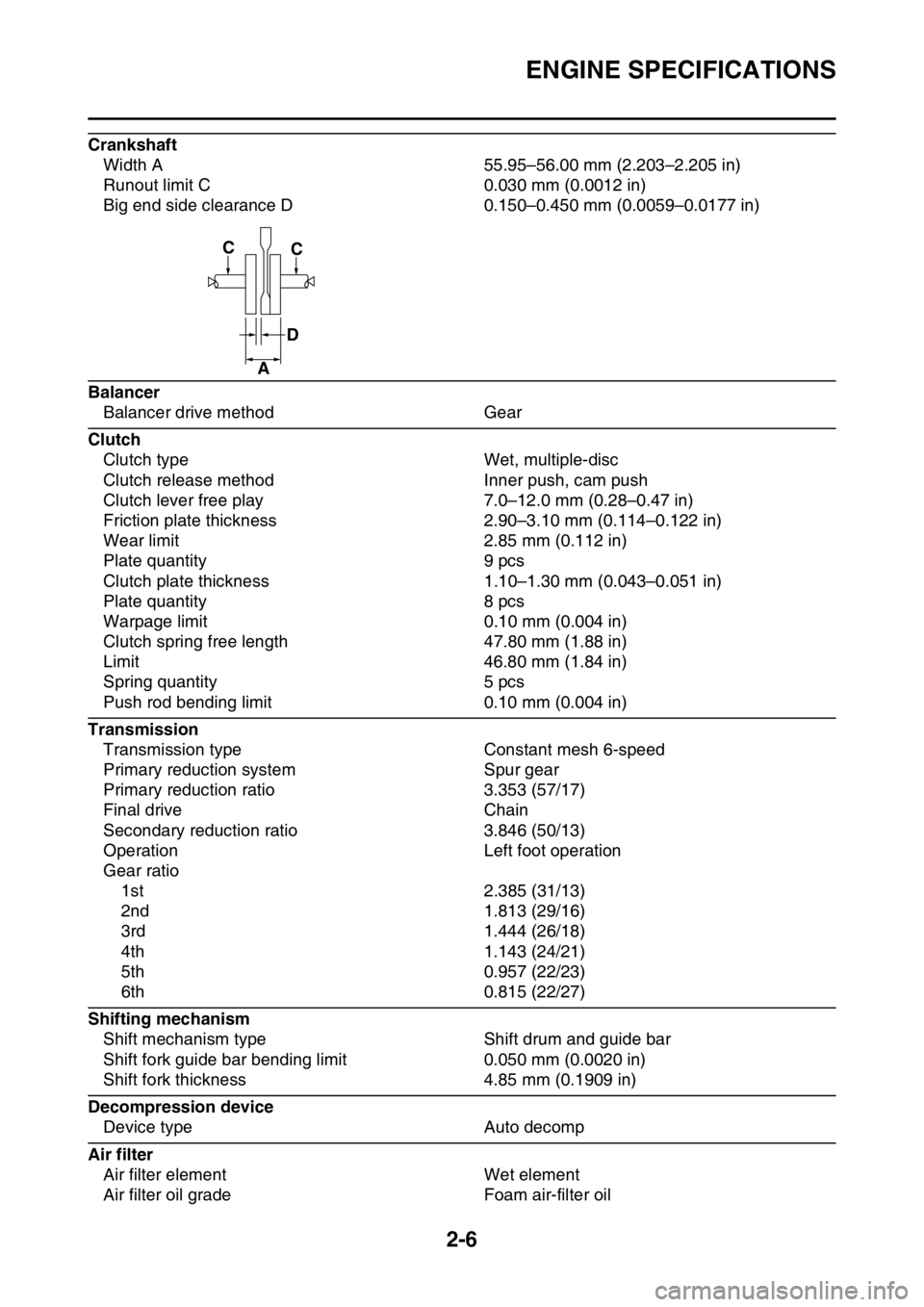
Crankshaft
Width A 55.95–56.00 mm (2.203–2.205 in)
Runout limit C 0.030 mm (0.0012 in)
Big end side clearance D 0.150–0.450 mm (0.0059–0.0177 in)
Balancer
Balancer drive method Gear
Clutch
Clutch type Wet, multiple-disc
Clutch release method Inner push, cam push
Clutch lever free play 7.0–12.0 mm (0.28–0.47 in)
Friction plate thickness 2.90–3.10 mm (0.114–0.122 in)
Wear limit 2.85 mm (0.112 in)
Plate quantity 9 pcs
Clutch plate thickness 1.10–1.30 mm (0.043–0.051 in)
Plate quantity 8 pcs
Warpage limit 0.10 mm (0.004 in)
Clutch spring free length 47.80 mm (1.88 in)
Limit 46.80 mm (1.84 in)
Spring quantity 5 pcs
Push rod bending limit 0.10 mm (0.004 in)
Transmission
Transmission type Constant mesh 6-speed
Primary reduction system Spur gear
Primary reduction ratio 3.353 (57/17)
Final drive Chain
Secondary reduction ratio 3.846 (50/13)
Operation Left foot operation
Gear ratio
1st 2.385 (31/13)
2nd 1.813 (29/16)
3rd 1.444 (26/18)
4th 1.143 (24/21)
5th 0.957 (22/23)
6th 0.815 (22/27)
Shifting mechanism
Shift mechanism type Shift drum and guide bar
Shift fork guide bar bending limit 0.050 mm (0.0020 in)
Shift fork thickness 4.85 mm (0.1909 in)
Decompression device
Device type Auto decomp
Air filter
Air filter element Wet element
Air filter oil grade Foam air-filter oil
CC
D
A
Page 69 of 430
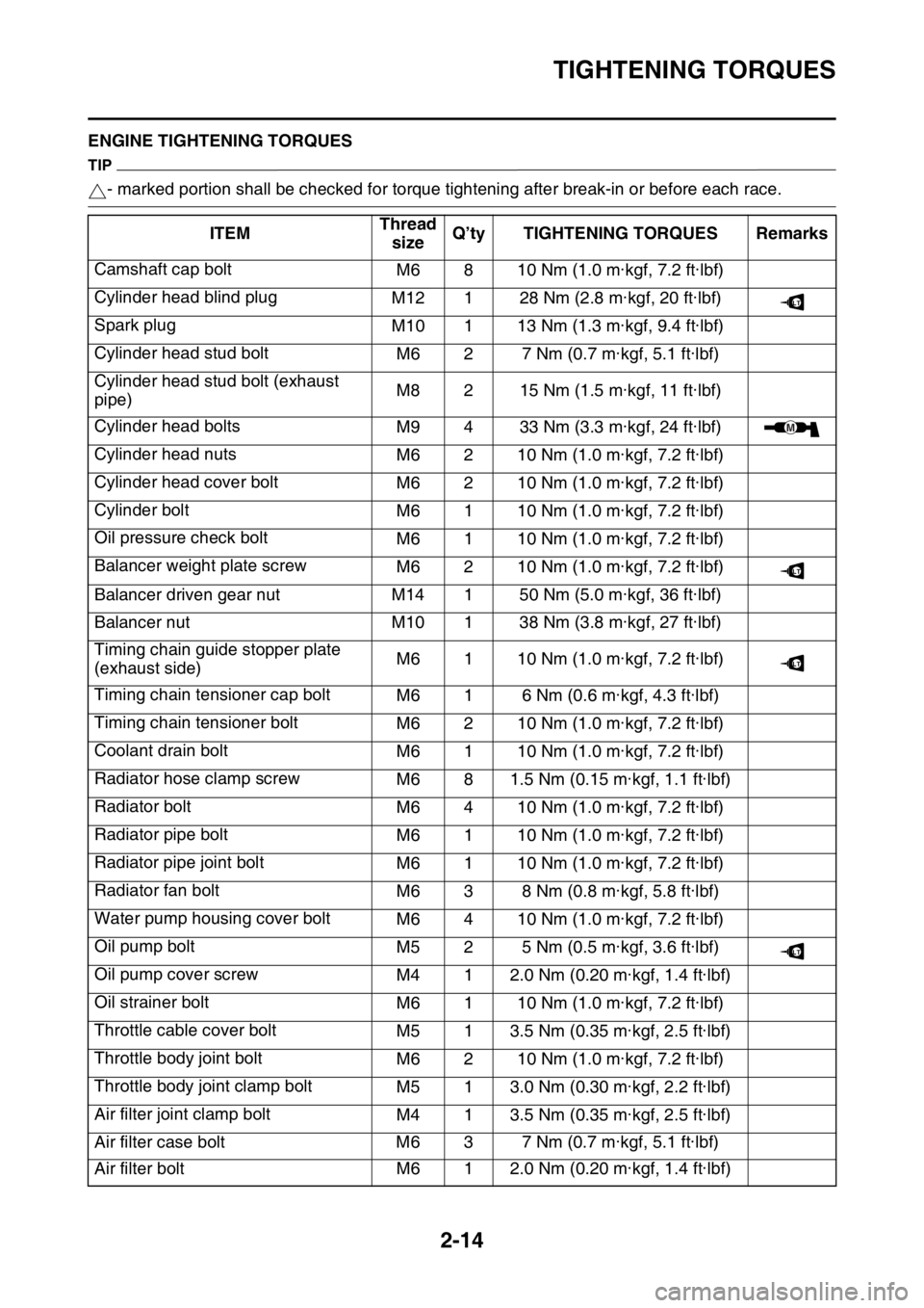
TIGHTENING TORQUES
2-14
EAS2GB2068ENGINE TIGHTENING TORQUES
TIP
- marked portion shall be checked for torque tightening after break-in or before each race.
ITEMThread
sizeQ’ty TIGHTENING TORQUES Remarks
Camshaft cap bolt
M6 8 10 Nm (1.0 m·kgf, 7.2 ft·lbf)
Cylinder head blind plug
M12 1 28 Nm (2.8 m·kgf, 20 ft·lbf)
Spark plug
M10 1 13 Nm (1.3 m·kgf, 9.4 ft·lbf)
Cylinder head stud bolt
M6 2 7 Nm (0.7 m·kgf, 5.1 ft·lbf)
Cylinder head stud bolt (exhaust
pipe)M8 2 15 Nm (1.5 m·kgf, 11 ft·lbf)
Cylinder head bolts
M9 4 33 Nm (3.3 m·kgf, 24 ft·lbf)
Cylinder head nuts
M6 2 10 Nm (1.0 m·kgf, 7.2 ft·lbf)
Cylinder head cover bolt
M6 2 10 Nm (1.0 m·kgf, 7.2 ft·lbf)
Cylinder bolt
M6 1 10 Nm (1.0 m·kgf, 7.2 ft·lbf)
Oil pressure check bolt
M6 1 10 Nm (1.0 m·kgf, 7.2 ft·lbf)
Balancer weight plate screw
M6 2 10 Nm (1.0 m·kgf, 7.2 ft·lbf)
Balancer driven gear nut M14 1 50 Nm (5.0 m·kgf, 36 ft·lbf)
Balancer nut M10 1 38 Nm (3.8 m·kgf, 27 ft·lbf)
Timing chain guide stopper plate
(exhaust side)M6 1 10 Nm (1.0 m·kgf, 7.2 ft·lbf)
Timing chain tensioner cap bolt
M6 1 6 Nm (0.6 m·kgf, 4.3 ft·lbf)
Timing chain tensioner bolt
M6 2 10 Nm (1.0 m·kgf, 7.2 ft·lbf)
Coolant drain bolt
M6 1 10 Nm (1.0 m·kgf, 7.2 ft·lbf)
Radiator hose clamp screw
M6 8 1.5 Nm (0.15 m·kgf, 1.1 ft·lbf)
Radiator bolt
M6 4 10 Nm (1.0 m·kgf, 7.2 ft·lbf)
Radiator pipe bolt
M6 1 10 Nm (1.0 m·kgf, 7.2 ft·lbf)
Radiator pipe joint bolt
M6 1 10 Nm (1.0 m·kgf, 7.2 ft·lbf)
Radiator fan bolt
M6 3 8 Nm (0.8 m·kgf, 5.8 ft·lbf)
Water pump housing cover bolt
M6 4 10 Nm (1.0 m·kgf, 7.2 ft·lbf)
Oil pump bolt
M5 2 5 Nm (0.5 m·kgf, 3.6 ft·lbf)
Oil pump cover screw
M4 1 2.0 Nm (0.20 m·kgf, 1.4 ft·lbf)
Oil strainer bolt
M6 1 10 Nm (1.0 m·kgf, 7.2 ft·lbf)
Throttle cable cover bolt
M5 1 3.5 Nm (0.35 m·kgf, 2.5 ft·lbf)
Throttle body joint bolt
M6 2 10 Nm (1.0 m·kgf, 7.2 ft·lbf)
Throttle body joint clamp bolt
M5 1 3.0 Nm (0.30 m·kgf, 2.2 ft·lbf)
Air filter joint clamp bolt
M4 1 3.5 Nm (0.35 m·kgf, 2.5 ft·lbf)
Air filter case bolt M6 3 7 Nm (0.7 m·kgf, 5.1 ft·lbf)
Air filter bolt M6 1 2.0 Nm (0.20 m·kgf, 1.4 ft·lbf)
LT
M
LT
LT
LT
Page 70 of 430

TIGHTENING TORQUES
2-15
Air filter guide holder screw
M5 8 2.5 Nm (0.25 m·kgf, 1.8 ft·lbf)
Air filter case cap screw
M5 1 2.5 Nm (0.25 m·kgf, 1.8 ft·lbf)
Starter knob/Idle screw
M12 1 2.1 Nm (0.21 m·kgf, 1.5 ft·lbf)
Throttle cable nut (pull)
M10 1 7 Nm (0.7 m·kgf, 5.1 ft·lbf)
Throttle cable nut (return)
M10 1 7 Nm (0.7 m·kgf, 5.1 ft·lbf)
Clutch cable adjuster and locknut
M6 1 4.0 Nm (0.40 m·kgf, 2.9 ft·lbf)
Clutch cable locknut (engine side)
M8 1 7 Nm (0.7 m·kgf, 5.1 ft·lbf)
Exhaust pipe nut
M8 2 See TIP.
Exhaust pipe protector screw
M6 4 10 Nm (1.0 m·kgf, 7.2 ft·lbf)
Exhaust pipe bracket bolt
M8 1 20 Nm (2.0 m·kgf, 14 ft·lbf)
Frame and silencer bolt (front) M8 1 30 Nm (3.0 m·kgf, 22 ft·lbf)
Frame and silencer bolt (rear) M8 1 30 Nm (3.0 m·kgf, 22 ft·lbf)
Exhaust pipe clamp bolt
M8 2 12 Nm (1.2 m·kgf, 8.7 ft·lbf)
Spark arrester bolt
M5 4 9 Nm (0.9 m·kgf, 6.5 ft·lbf)
Muffler cap bolt
M5 6 5 Nm (0.5 m·kgf, 3.6 ft·lbf)
Oil nozzle bolt
M5 1 5 Nm (0.5 m·kgf, 3.6 ft·lbf)
Engine oil drain bolt
M10 1 20 Nm (2.0 m·kgf, 14 ft·lbf)
Crankcase bolt
M6 12 12 Nm (1.2 m·kgf, 8.7 ft·lbf)
Clutch cable holder bolt
M6 2 10 Nm (1.0 m·kgf, 7.2 ft·lbf)
Crankshaft end accessing screw
M36 1 10 Nm (1.0 m·kgf, 7.2 ft·lbf)
Timing mark accessing screw
M14 1 6 Nm (0.6 m·kgf, 4.3 ft·lbf)
Drive chain sprocket cover bolt
M6 2 7 Nm (0.7 m·kgf, 5.1 ft·lbf)
Crankcase bearing cover plate
screwM6 6 10 Nm (1.0 m·kgf, 7.2 ft·lbf)
Crankcase bearing cover plate
screw (crankshaft)M8 4 22 Nm (2.2 m·kgf, 16 ft·lbf)
Oil passage squeeze nozzle
M8 1 3.0 Nm (0.30 m·kgf, 2.2 ft·lbf)
Clutch cover bolt
M6 7 10 Nm (1.0 m·kgf, 7.2 ft·lbf)
Left crankcase cover bolt
M6 7 10 Nm (1.0 m·kgf, 7.2 ft·lbf)
Right crankcase cover bolt
M6 11 10 Nm (1.0 m·kgf, 7.2 ft·lbf)
Oil filter element cover bolt
M6 2 10 Nm (1.0 m·kgf, 7.2 ft·lbf)
Kick shaft ratchet wheel guide bolt
M6 2 12 Nm (1.2 m·kgf, 8.7 ft·lbf)
Kick starter lever bolt
M8 1 33 Nm (3.3 m·kgf, 24 ft·lbf)
Kick starter lever boss screw
M6 1 7 Nm (0.7 m·kgf, 5.1 ft·lbf)
Primary drive gear nut
M16 1 75 Nm (7.5 m·kgf, 54 ft·lbf)
Clutch spring bolt
M6 5 10 Nm (1.0 m·kgf, 7.2 ft·lbf) ITEMThread
sizeQ’ty TIGHTENING TORQUES Remarks
LT
LT
LT
LT
LT
LT
LT
Page 91 of 430

CABLE ROUTING DIAGRAM
2-36
1. Clamp
2. Cylinder head breather hose
3. Throttle position sensor lead
4. Joint coupler
5. Intake air temperature sensor coupler
6. Intake air pressure sensor lead
7. Wire harness
8. Injector lead
9. Throttle body
10. Injector coupler
11. Starter motor lead
12. Plastic band
13. Fuel sender coupler
14. High tension cord
15. Spark plug cap
16. Cylinder head cover
17. Fuel hose
18. Fuel sender
19. Sub-wire harness
20. Crankcase breather hose
21. Radiator breather hose
22. Radiator hose
23. Down tube
24. Starter motor
25. Neutral switch lead
26. AC magneto lead
27. Clutch cable
28. Radiator
29. Air filter case breather hose
30. Breather hose clamp
31. Grommet (high tension cord)
32. ECU
33. Air filter case
34. Sub-wire harness coupler
35. Engine bracket
A. Fix the wire harness, clutch switch lead and start
switch lead by the plastic clamp, and insert the
projection of the plastic clamp into the hole in the
sheet metal of the radiator.
B. Route each lead so that the leads are not pinched
between the tank rail and air filter joint.
C. Insert the projection of the wire harness into the
hole in the frame.
D. Route the cylinder head breather hose without it
crossing the starter motor lead.
E. Pass the cylinder head breather hose between
the throttle cable and rectifier/regulator lead.
F. Connect the sub-wire harness to the wire har-
ness.
G. Pass the high tension cord above the fuel hose.
H. ±10°
I. Install the spark plug cap with this facing the right
of the vehicle.
J. Push the spark plug cap home, where there shall
be no gap between it and the cylinder head cover.
K. Pass the radiator breather hose between the
down tubes.
L. Apply adhesive to the slit and inside of the grom-
met, and then fix the grommet according to the
specified dimensions.
M. Pass the sub-wire harness between the ECU and
the air filter case.
N. Insert the coupler of the sub-wire harness into the
rib of the air filter case.
O. Route the radiator breather hose through be-
tween the radiator hose, down tube and engine
bracket.
Page 93 of 430

CABLE ROUTING DIAGRAM
2-38
1. Cable guide
2. Speed sensor lead
3. Joint coupler
4. Ground lead
5. Throttle position sensor lead
6. Throttle position sensor coupler
7. Radiator breather hose
8. Cylinder head breather hose
9. Crankcase breather hose
10. Radiator hose
11. Fuel hose
12. Engine ground lead
13. Coolant temperature sensor coupler
14. Radiator fan motor lead
15. Intake air pressure sensor coupler
16. Intake air temperature sensor coupler
17. Start switch coupler
18. Radiator fan motor coupler
19. Clutch switch coupler
20. Air filter case
21. Plate
22. Bracket
A. Pass the wire harness under the start switch lead
and clutch switch lead.
B. Insert and fix the joint coupler to the plate. After
fixing it, attach the cover.
C. Pass the throttle position sensor lead to the out-
side of the tension arm (the outside of the vehi-
cle).
D. After connecting the throttle position sensor cou-
pler, attach the cover.
E. Pass the radiator breather hose to the outside of
the tension arm and the throttle position sensor
lead (the outside of the vehicle), and to the inside
of the radiator hose (the side of the vehicle).
F. 45°
G. Install the engine ground lead within a range of
45° from a location where it will not run over the
step difference of the radiator hose joint. Both
sides of the engine ground lead terminal can be
used.
H. Attach the coupler cover to the coolant tempera-
ture sensor coupler.
I. Pass the radiator fan motor lead to the inside of
the tension arm (the side of the vehicle).
J. Install the ground lead terminal between the plate
and the bolt.
K. Fix the ground lead terminal to the detent in the
plate. For the ground lead terminal, either side
will do.
L. Detent