YAMAHA WR 250F 2017 Owners Manual
Manufacturer: YAMAHA, Model Year: 2017, Model line: WR 250F, Model: YAMAHA WR 250F 2017Pages: 432, PDF Size: 14.14 MB
Page 301 of 432
CRANKCASE
6-72
EAS2GBB310
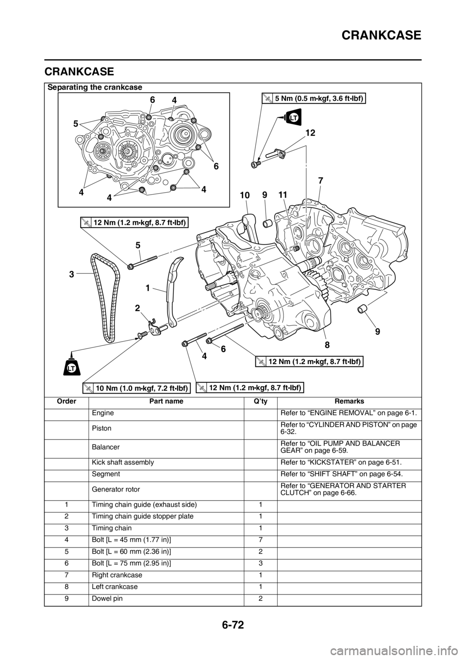
CRANKCASE
Separating the crankcase
Order Part name Q’ty Remarks
Engine Refer to “ENGINE REMOVAL” on page 6-1.
PistonRefer to “CYLINDER AND PISTON” on page
6-32.
BalancerRefer to “OIL PUMP AND BALANCER
GEAR” on page 6-59.
Kick shaft assembly Refer to “KICKSTATER” on page 6-51.
Segment Refer to “SHIFT SHAFT” on page 6-54.
Generator rotorRefer to “GENERATOR AND STARTER
CLUTCH” on page 6-66.
1 Timing chain guide (exhaust side) 1
2 Timing chain guide stopper plate 1
3 Timing chain 1
4 Bolt [L = 45 mm (1.77 in)] 7
5 Bolt [L = 60 mm (2.36 in)] 2
6 Bolt [L = 75 mm (2.95 in)] 3
7 Right crankcase 1
8 Left crankcase 1
9 Dowel pin 2
3
1 5
2
6410 56
4
4
446
9117
8
9
LT
12
LT
10 Nm (1.0 m kgf, 7.2 ft Ibf)T.R.
12 Nm (1.2 m kgf, 8.7 ft Ibf)T.R.
12 Nm (1.2 m kgf, 8.7 ft Ibf)T.R.
12 Nm (1.2 m kgf, 8.7 ft Ibf)T.R.
5 Nm (0.5 m kgf, 3.6 ft Ibf)T.R.
Page 302 of 432
CRANKCASE
6-73
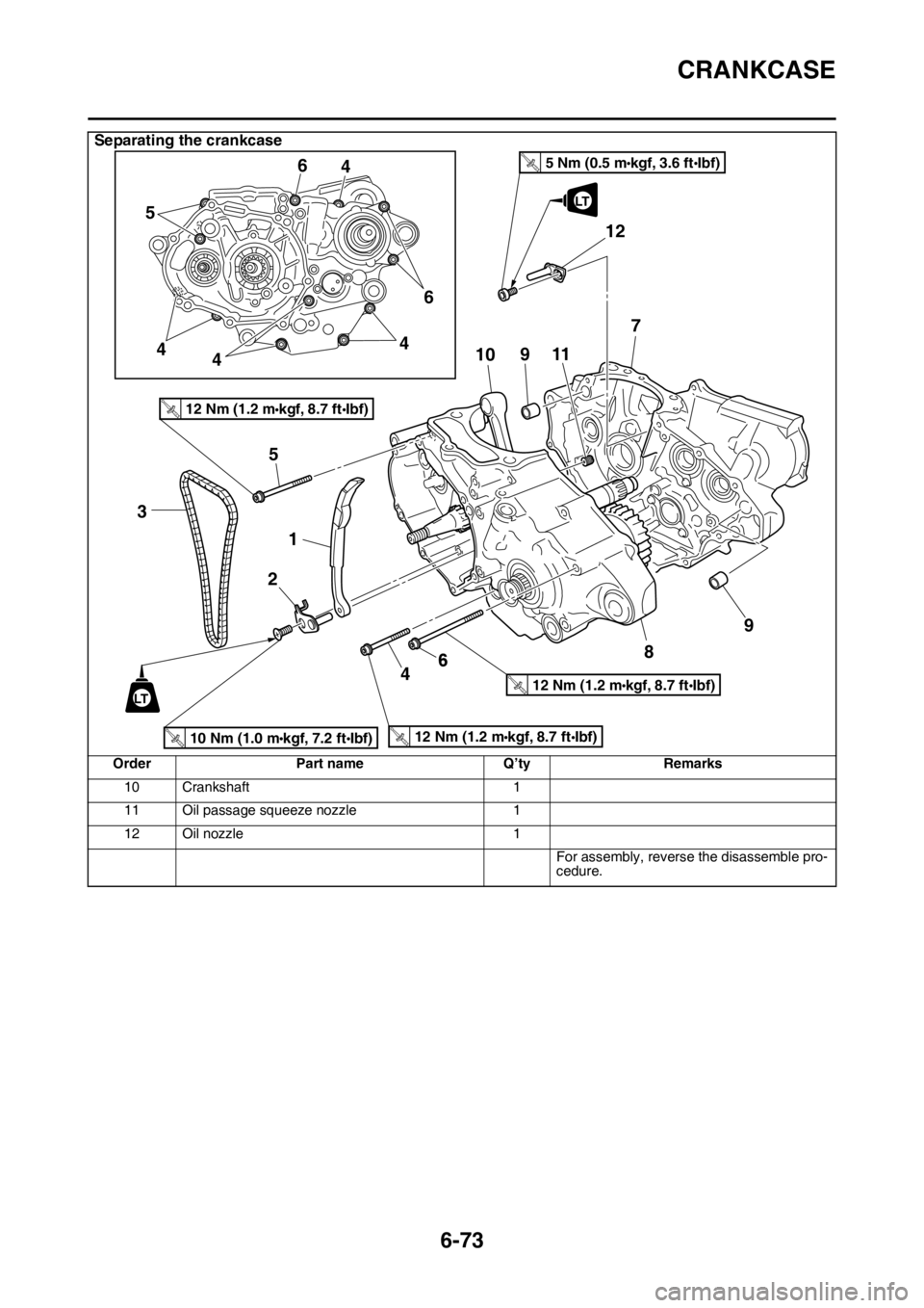
10 Crankshaft 1
11 Oil passage squeeze nozzle 1
12 Oil nozzle 1
For assembly, reverse the disassemble pro-
cedure.
Separating the crankcase
Order Part name Q’ty Remarks
3
1 5
2
6410 56
4
4
446
9117
8
9
LT
12
LT
10 Nm (1.0 m kgf, 7.2 ft Ibf)T.R.
12 Nm (1.2 m kgf, 8.7 ft Ibf)T.R.
12 Nm (1.2 m kgf, 8.7 ft Ibf)T.R.
12 Nm (1.2 m kgf, 8.7 ft Ibf)T.R.
5 Nm (0.5 m kgf, 3.6 ft Ibf)T.R.
Page 303 of 432
CRANKCASE
6-74
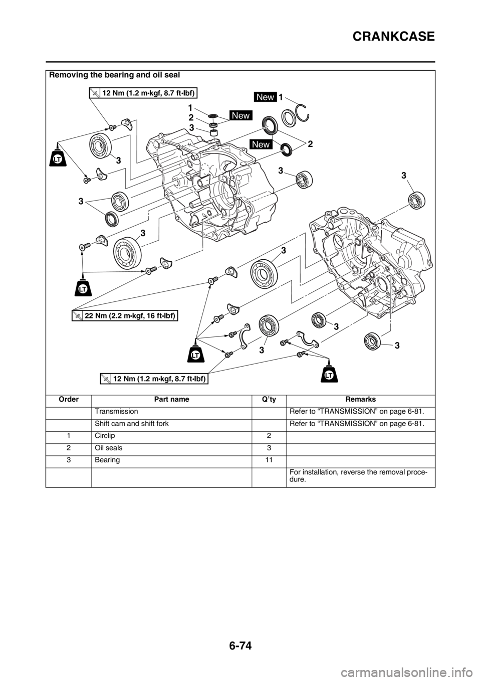
Removing the bearing and oil seal
Order Part name Q’ty Remarks
Transmission Refer to “TRANSMISSION” on page 6-81.
Shift cam and shift fork Refer to “TRANSMISSION” on page 6-81.
1 Circlip 2
2Oil seals 3
3 Bearing 11
For installation, reverse the removal proce-
dure.
LT
LT
2
3
33
3
3
3 3
33
New
1
1
2
3
New
New
LT
22 Nm (2.2 m kgf, 16 ft Ibf)T.R.
12 Nm (1.2 m kgf, 8.7 ft Ibf)T.R.
12 Nm (1.2 m kgf, 8.7 ft Ibf)T.R.
LT
Page 304 of 432
CRANKCASE
6-75
EAS2GBB311DISASSEMBLING THE CRANKCASE
1. Separate:
• Right crankcase
• Left crankcase
▼▼▼▼▼▼▼▼▼▼▼▼▼▼▼▼▼▼▼▼▼▼▼▼▼▼▼▼▼▼▼▼
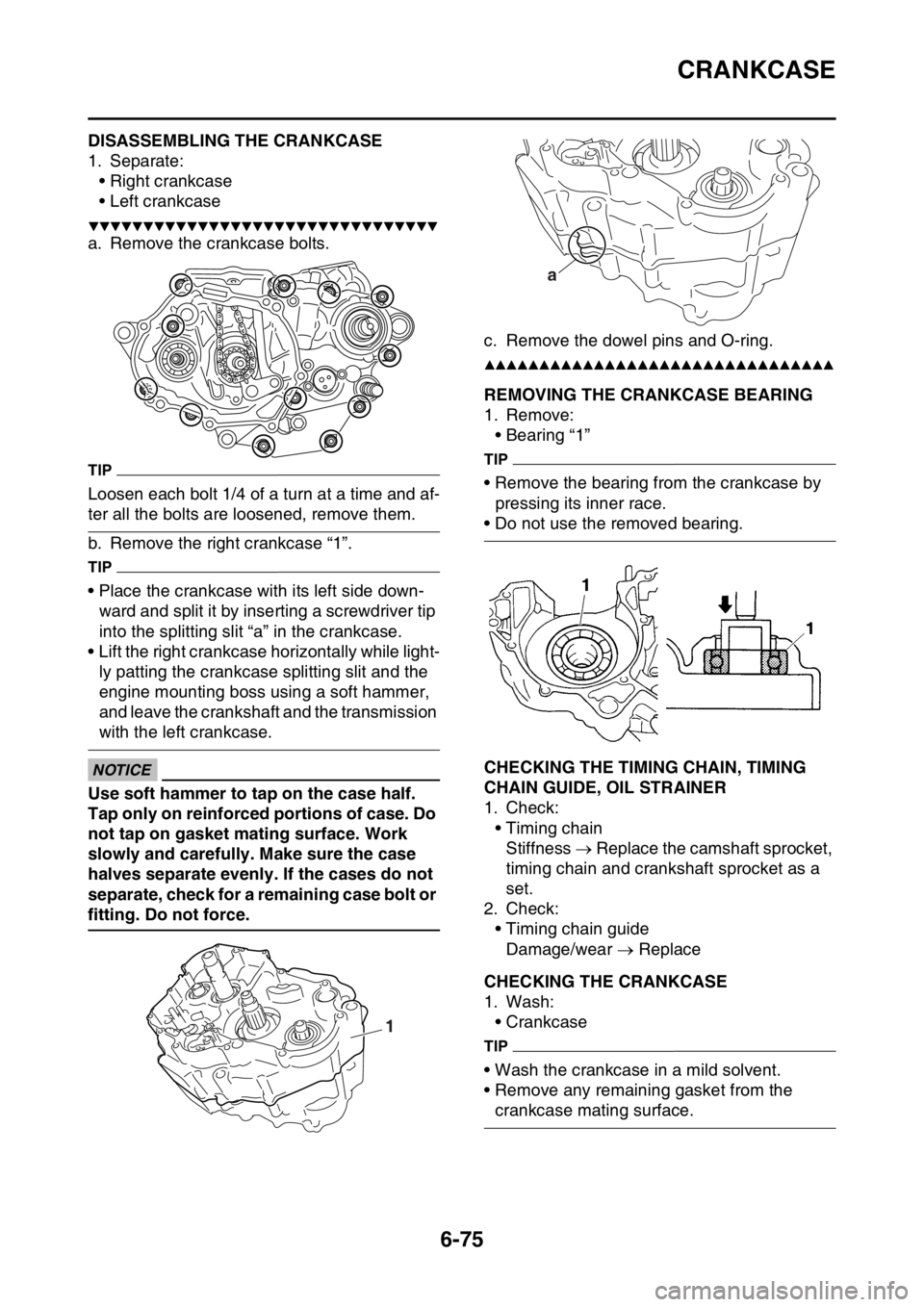
a. Remove the crankcase bolts.
TIP
Loosen each bolt 1/4 of a turn at a time and af-
ter all the bolts are loosened, remove them.
b. Remove the right crankcase “1”.
TIP
• Place the crankcase with its left side down-
ward and split it by inserting a screwdriver tip
into the splitting slit “a” in the crankcase.
• Lift the right crankcase horizontally while light-
ly patting the crankcase splitting slit and the
engine mounting boss using a soft hammer,
and leave the crankshaft and the transmission
with the left crankcase.
ECA
NOTICE
Use soft hammer to tap on the case half.
Tap only on reinforced portions of case. Do
not tap on gasket mating surface. Work
slowly and carefully. Make sure the case
halves separate evenly. If the cases do not
separate, check for a remaining case bolt or
fitting. Do not force.c. Remove the dowel pins and O-ring.
▲▲▲▲▲▲▲▲▲▲▲▲▲▲▲▲▲▲▲▲▲▲▲▲▲▲▲▲▲▲▲▲
EAS2GBB312REMOVING THE CRANKCASE BEARING
1. Remove:
• Bearing “1”
TIP
• Remove the bearing from the crankcase by
pressing its inner race.
• Do not use the removed bearing.
EAS2GBB313CHECKING THE TIMING CHAIN, TIMING
CHAIN GUIDE, OIL STRAINER
1. Check:
• Timing chain
Stiffness Replace the camshaft sprocket,
timing chain and crankshaft sprocket as a
set.
2. Check:
• Timing chain guide
Damage/wear Replace
EAS2GBB314CHECKING THE CRANKCASE
1. Wash:
• Crankcase
TIP
• Wash the crankcase in a mild solvent.
• Remove any remaining gasket from the
crankcase mating surface.
1
a
Page 305 of 432
CRANKCASE
6-76
2. Check:
• Crankcase
Crack/damage Replace.
• Oil delivery passages
Obstruction Blow out with compressed
air.
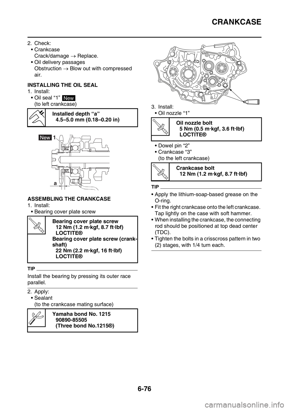
EAS2GBB315INSTALLING THE OIL SEAL
1. Install:
• Oil seal “1”
(to left crankcase)
EAS2GBB316ASSEMBLING THE CRANKCASE
1. Install:
• Bearing cover plate screw
TIP
Install the bearing by pressing its outer race
parallel.
2. Apply:
• Sealant
(to the crankcase mating surface)3. Install:
• Oil nozzle “1”
• Dowel pin “2”
• Crankcase “3”
(to the left crankcase)
TIP
• Apply the lithium-soap-based grease on the
O-ring.
• Fit the right crankcase onto the left crankcase.
Tap lightly on the case with soft hammer.
• When installing the crankcase, the connecting
rod should be positioned at top dead center
(TDC).
• Tighten the bolts in a crisscross pattern in two
(2) stages, with 1/4 turn each. Installed depth “a”
4.5–5.0 mm (0.18–0.20 in)
Bearing cover plate screw
12 Nm (1.2 m·kgf, 8.7 ft·lbf)
LOCTITE®
Bearing cover plate screw (crank-
shaft)
22 Nm (2.2 m·kgf, 16 ft·lbf)
LOCTITE®
Yamaha bond No. 1215
90890-85505
(Three bond No.1215®)
New
a 1
T R..
Oil nozzle bolt
5 Nm (0.5 m·kgf, 3.6 ft·lbf)
LOCTITE®
Crankcase bolt
12 Nm (1.2 m·kgf, 8.7 ft·lbf)
T R..
T R..
Page 306 of 432
CRANKCASE
6-77
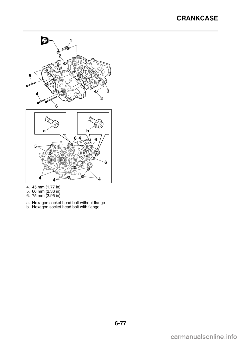
4. 45 mm (1.77 in)
5. 60 mm (2.36 in)
6. 75 mm (2.95 in)
a. Hexagon socket head bolt without flange
b. Hexagon socket head bolt with flange
5
4
54
446 6 6
4
ab2
1LT
23
6
Page 307 of 432
CRANKSHAFT ASSEMBLY AND BALANCER SHAFT
6-78
EAS2GBB317
CRANKSHAFT ASSEMBLY AND BALANCER SHAFT
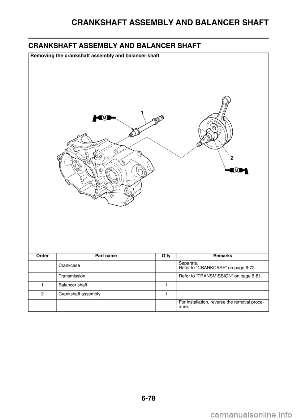
Removing the crankshaft assembly and balancer shaft
Order Part name Q’ty Remarks
CrankcaseSeparate.
Refer to “CRANKCASE” on page 6-72.
Transmission Refer to “TRANSMISSION” on page 6-81.
1 Balancer shaft 1
2 Crankshaft assembly 1
For installation, reverse the removal proce-
dure.
M
M
1
2
Page 308 of 432
CRANKSHAFT ASSEMBLY AND BALANCER SHAFT
6-79
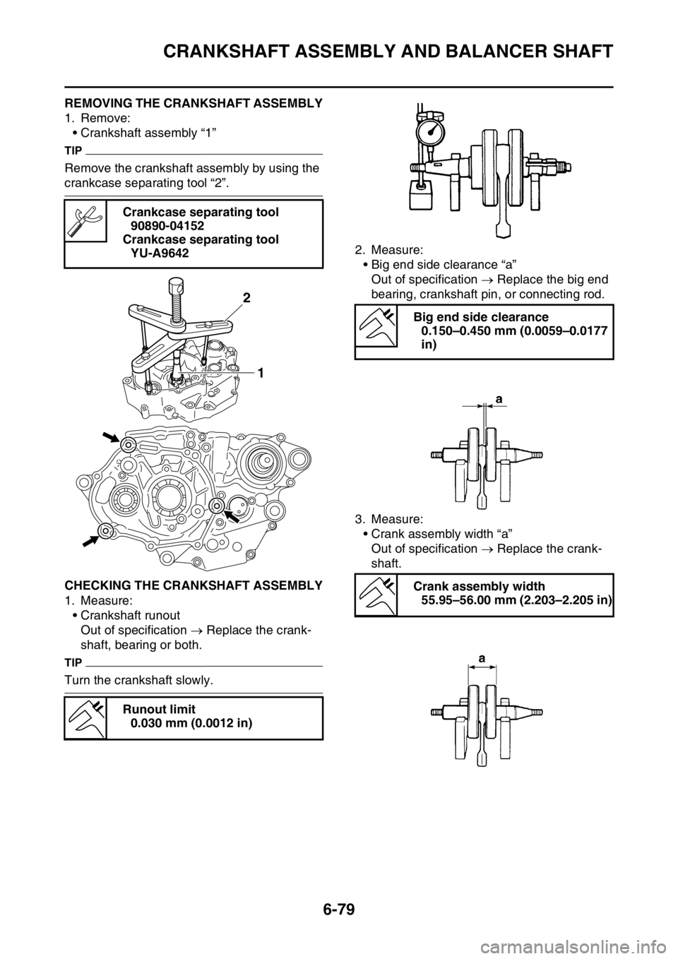
EAS2GBB318REMOVING THE CRANKSHAFT ASSEMBLY
1. Remove:
• Crankshaft assembly “1”
TIP
Remove the crankshaft assembly by using the
crankcase separating tool “2”.
EAS2GBB319CHECKING THE CRANKSHAFT ASSEMBLY
1. Measure:
• Crankshaft runout
Out of specification Replace the crank-
shaft, bearing or both.
TIP
Turn the crankshaft slowly.2. Measure:
• Big end side clearance “a”
Out of specification Replace the big end
bearing, crankshaft pin, or connecting rod.
3. Measure:
• Crank assembly width “a”
Out of specification Replace the crank-
shaft. Crankcase separating tool
90890-04152
Crankcase separating tool
YU-A9642
Runout limit
0.030 mm (0.0012 in)
2
1
Big end side clearance
0.150–0.450 mm (0.0059–0.0177
in)
Crank assembly width
55.95–56.00 mm (2.203–2.205 in)
Page 309 of 432
CRANKSHAFT ASSEMBLY AND BALANCER SHAFT
6-80
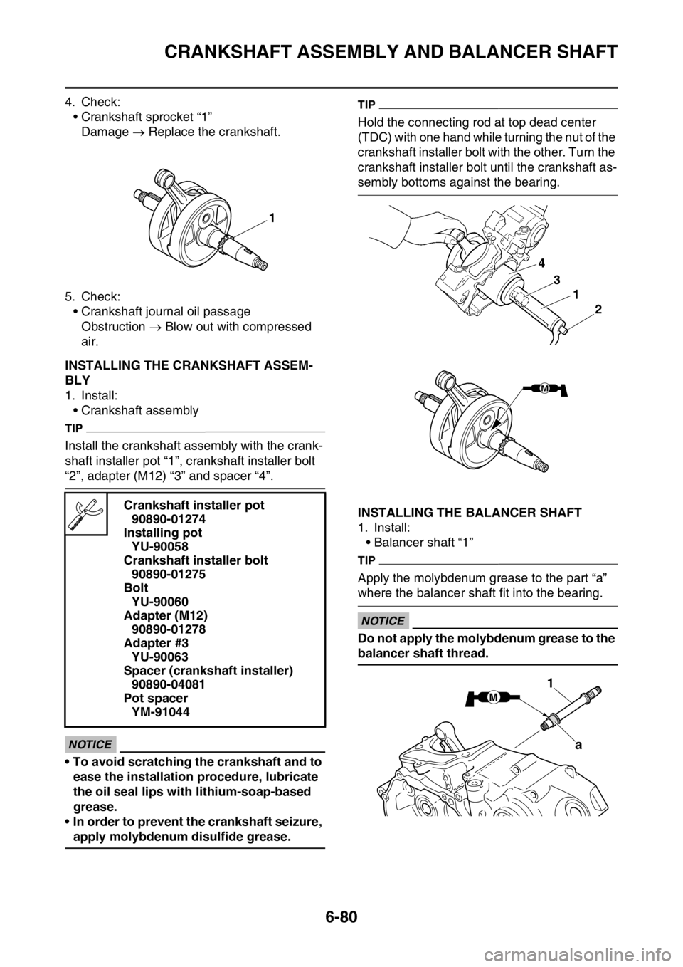
4. Check:
• Crankshaft sprocket “1”
Damage Replace the crankshaft.
5. Check:
• Crankshaft journal oil passage
Obstruction Blow out with compressed
air.
EAS2GBB320INSTALLING THE CRANKSHAFT ASSEM-
BLY
1. Install:
• Crankshaft assembly
TIP
Install the crankshaft assembly with the crank-
shaft installer pot “1”, crankshaft installer bolt
“2”, adapter (M12) “3” and spacer “4”.
ECA
NOTICE
• To avoid scratching the crankshaft and to
ease the installation procedure, lubricate
the oil seal lips with lithium-soap-based
grease.
• In order to prevent the crankshaft seizure,
apply molybdenum disulfide grease.
TIP
Hold the connecting rod at top dead center
(TDC) with one hand while turning the nut of the
crankshaft installer bolt with the other. Turn the
crankshaft installer bolt until the crankshaft as-
sembly bottoms against the bearing.
EAS2GBB321INSTALLING THE BALANCER SHAFT
1. Install:
• Balancer shaft “1”
TIP
Apply the molybdenum grease to the part “a”
where the balancer shaft fit into the bearing.
ECA
NOTICE
Do not apply the molybdenum grease to the
balancer shaft thread. Crankshaft installer pot
90890-01274
Installing pot
YU-90058
Crankshaft installer bolt
90890-01275
Bolt
YU-90060
Adapter (M12)
90890-01278
Adapter #3
YU-90063
Spacer (crankshaft installer)
90890-04081
Pot spacer
YM-91044
1
M
1
a
Page 310 of 432
TRANSMISSION
6-81
EAS2GBB322
TRANSMISSION
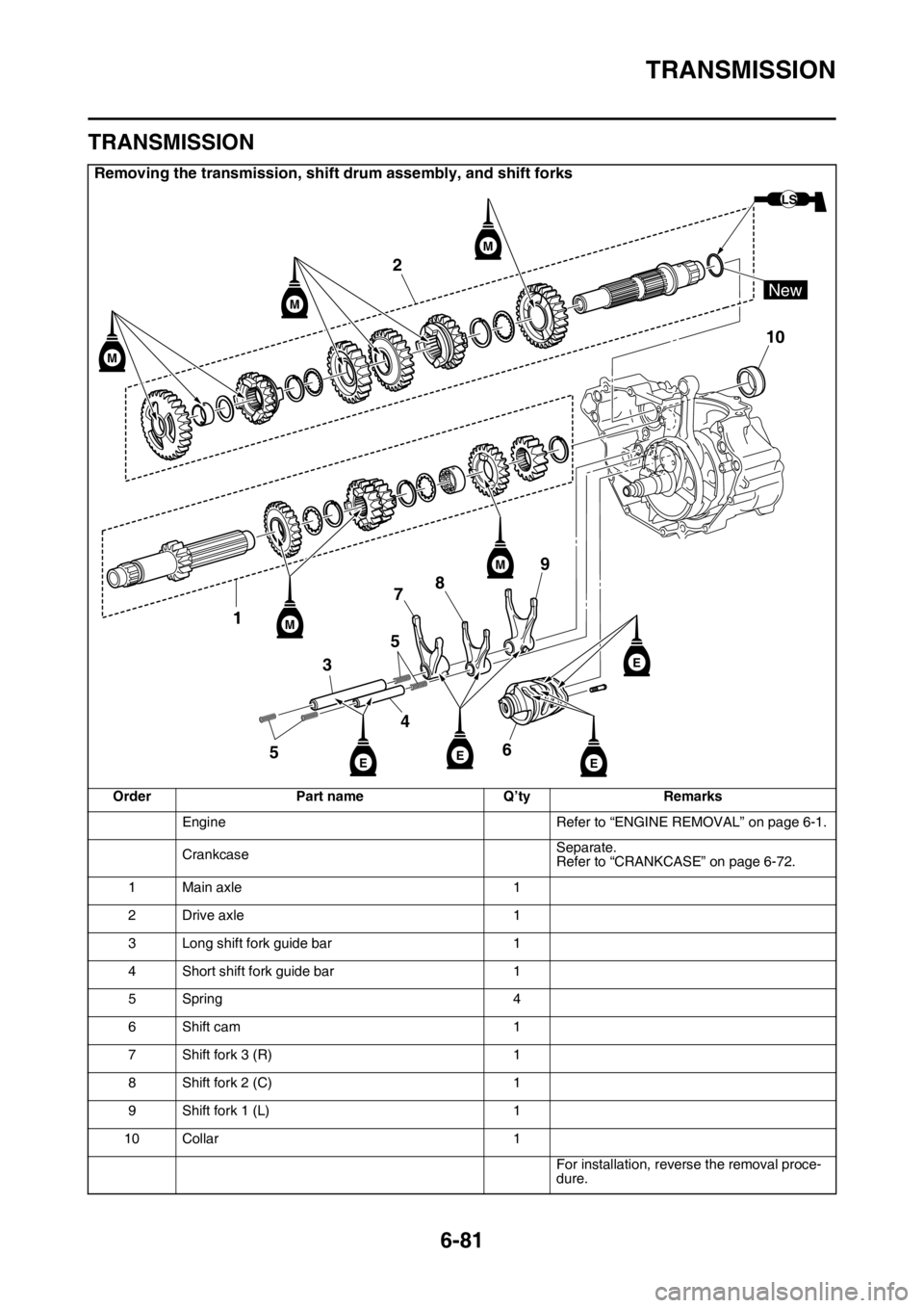
Removing the transmission, shift drum assembly, and shift forks
Order Part name Q’ty Remarks
Engine Refer to “ENGINE REMOVAL” on page 6-1.
CrankcaseSeparate.
Refer to “CRANKCASE” on page 6-72.
1 Main axle 1
2 Drive axle 1
3 Long shift fork guide bar 1
4 Short shift fork guide bar 1
5Spring 4
6 Shift cam 1
7 Shift fork 3 (R) 1
8 Shift fork 2 (C) 1
9 Shift fork 1 (L) 1
10 Collar 1
For installation, reverse the removal proce-
dure.
2
10
1
53
4 578
69
M
M
M
M
EE
E
E
LS
New
M