YAMAHA WR 250F 2017 Owners Manual
Manufacturer: YAMAHA, Model Year: 2017, Model line: WR 250F, Model: YAMAHA WR 250F 2017Pages: 432, PDF Size: 14.14 MB
Page 331 of 432

THROTTLE BODY
8-8
9 Fuel hose 1
10 Exhaust pipe bracket 1
11Throttle body
1
12 Throttle body joint 1
For installation, reverse the removal proce-
dure.
Removing the throttle body
Order Part name Q’ty Remarks
3
1
2
7
11
12
10
9
4
8
6
5
3.5 Nm (0.35 m kgf, 2.5 ft Ibf)T.R.
3.5 Nm (0.35 m kgf, 2.5 ft Ibf)T.R.
7 Nm (0.7 m kgf, 5.1 ft Ibf)T.R.
3.0 Nm (0.30 m kgf, 2.2 ft Ibf)T.R.
10 Nm (1.0 m kgf, 7.2 ft Ibf)T.R.
Page 332 of 432

THROTTLE BODY
8-9
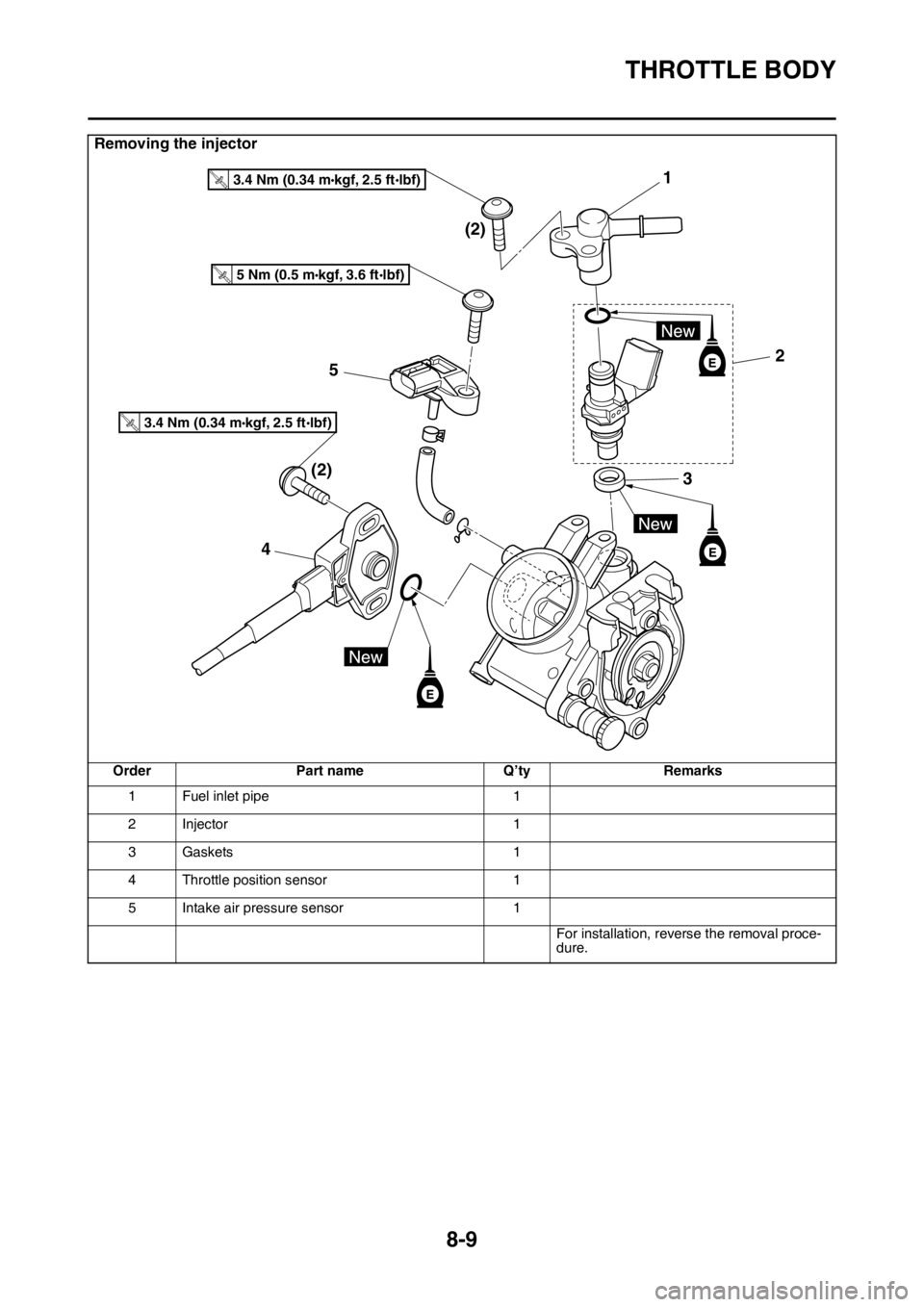
Removing the injector
Order Part name Q’ty Remarks
1 Fuel inlet pipe 1
2Injector 1
3 Gaskets 1
4 Throttle position sensor 1
5 Intake air pressure sensor 1
For installation, reverse the removal proce-
dure.
1
2 (2)
(2)5
43
T.R.3.4 Nm (0.34 mlbf) kgf, 2.5 ft
T.R.5 Nm (0.5 mlbf) kgf, 3.6 ft
T.R.3.4 Nm (0.34 mlbf) kgf, 2.5 ft
Page 333 of 432

THROTTLE BODY
8-10
EAS2GBB352CHECKING THE INJECTOR
1. Check:
• Injectors
Obstruction Replace, and check the fuel
pump and the fuel injection system.
Refer to “FUEL INJECTION SYSTEM” on
page 9-28.
Deposits Replace.
Damage Replace.
2. Check:
• Injector resistance
Refer to “CHECKING THE FUEL INJEC-
TOR” on page 9-81.
EAS2GBB353CHECKING THE THROTTLE BODY
1. Check:
• Throttle body
Cracks/damage Replace.
2. Check:
• Fuel passages
Obstructions Clean.
ECA
NOTICE
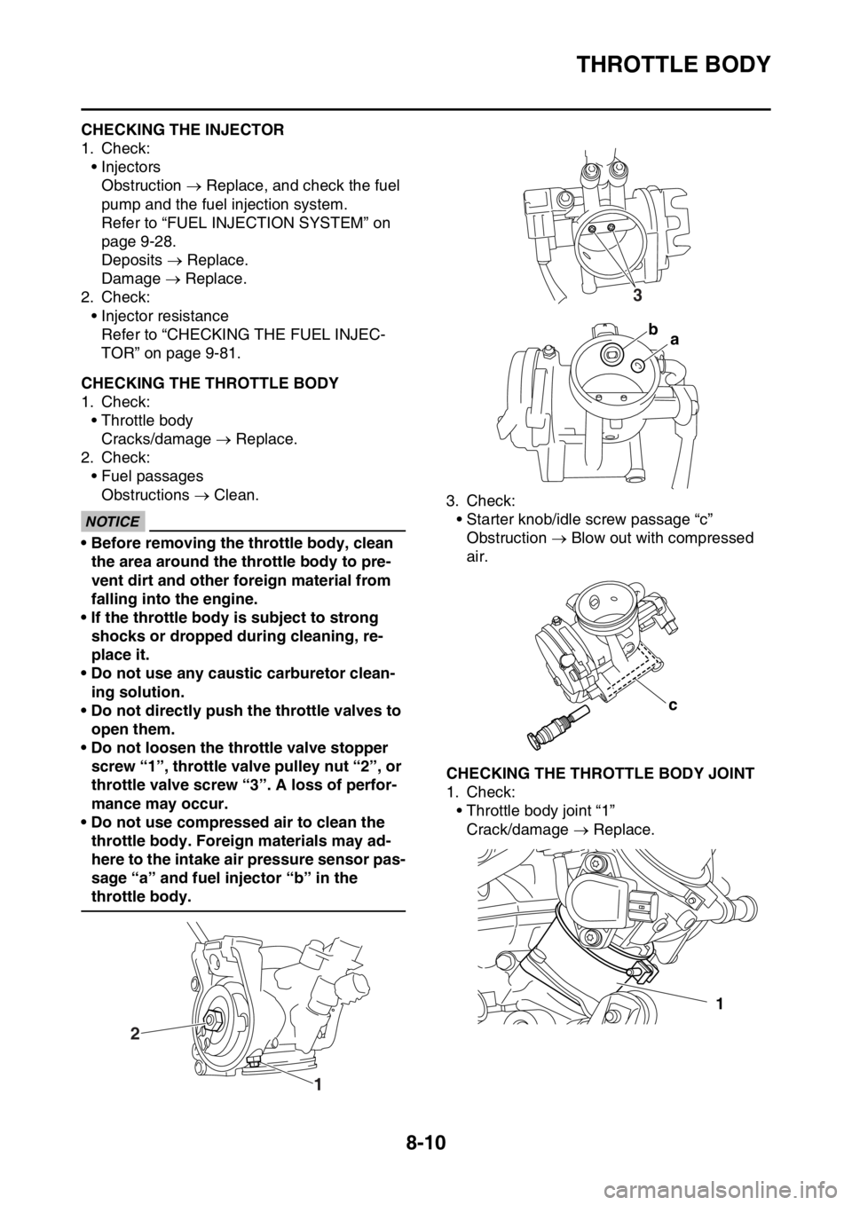
• Before removing the throttle body, clean
the area around the throttle body to pre-
vent dirt and other foreign material from
falling into the engine.
• If the throttle body is subject to strong
shocks or dropped during cleaning, re-
place it.
• Do not use any caustic carburetor clean-
ing solution.
• Do not directly push the throttle valves to
open them.
• Do not loosen the throttle valve stopper
screw “1”, throttle valve pulley nut “2”, or
throttle valve screw “3”. A loss of perfor-
mance may occur.
• Do not use compressed air to clean the
throttle body. Foreign materials may ad-
here to the intake air pressure sensor pas-
sage “a” and fuel injector “b” in the
throttle body.3. Check:
• Starter knob/idle screw passage “c”
Obstruction Blow out with compressed
air.
EAS2GBB354CHECKING THE THROTTLE BODY JOINT
1. Check:
• Throttle body joint “1”
Crack/damage Replace.
1 2
3
ba
c
1
Page 334 of 432

THROTTLE BODY
8-11
EAS2GBB355ADJUSTING THE THROTTLE POSITION
SENSOR
EWA
WARNING
• Handle the throttle position sensor with
special care.
• Never subject the throttle position sensor
to strong shocks. If the throttle position
sensor is dropped, replace it.
1. Check:
• Throttle position sensor
Refer to “CHECKING THE THROTTLE PO-
SITION SENSOR” on page 9-79.
2. Adjust:
• Throttle position sensor angle
▼▼▼▼▼▼▼▼▼▼▼▼▼▼▼▼▼▼▼▼▼▼▼▼▼▼▼▼▼▼▼▼
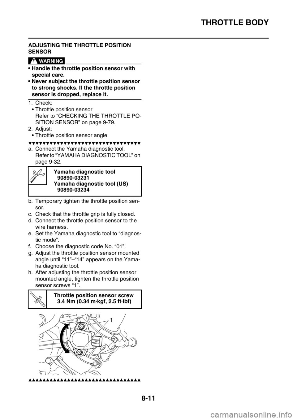
a. Connect the Yamaha diagnostic tool.
Refer to “YAMAHA DIAGNOSTIC TOOL” on
page 9-32.
b. Temporary tighten the throttle position sen-
sor.
c. Check that the throttle grip is fully closed.
d. Connect the throttle position sensor to the
wire harness.
e. Set the Yamaha diagnostic tool to “diagnos-
tic mode”.
f. Choose the diagnostic code No. “01”.
g. Adjust the throttle position sensor mounted
angle until “11”–“14” appears on the Yama-
ha diagnostic tool.
h. After adjusting the throttle position sensor
mounted angle, tighten the throttle position
sensor screws “1”.
▲▲▲▲▲▲▲▲▲▲▲▲▲▲▲▲▲▲▲▲▲▲▲▲▲▲▲▲▲▲▲▲
Yamaha diagnostic tool
90890-03231
Yamaha diagnostic tool (US)
90890-03234
Throttle position sensor screw
3.4 Nm (0.34 m·kgf, 2.5 ft·lbf)
T R..
1
Page 335 of 432

9
ELECTRICAL SYSTEM
IGNITION SYSTEM.......................................................................................... 9-2
CIRCUIT DIAGRAM ................................................................................... 9-2
TROUBLESHOOTING ............................................................................... 9-4
ELECTRIC STARTING SYSTEM..................................................................... 9-6
CIRCUIT DIAGRAM ................................................................................... 9-6
STARTING CIRCUIT CUT-OFF SYSTEM OPERATION ........................... 9-8
TROUBLESHOOTING ............................................................................. 9-10
CHARGING SYSTEM..................................................................................... 9-12
CIRCUIT DIAGRAM ................................................................................. 9-12
TROUBLESHOOTING ............................................................................. 9-14
LIGHTING SYSTEM....................................................................................... 9-16
CIRCUIT DIAGRAM ................................................................................. 9-16
TROUBLESHOOTING ............................................................................. 9-18
SIGNALING SYSTEM.................................................................................... 9-20
CIRCUIT DIAGRAM ................................................................................. 9-20
TROUBLESHOOTING ............................................................................. 9-22
COOLING SYSTEM........................................................................................ 9-24
CIRCUIT DIAGRAM ................................................................................. 9-24
TROUBLESHOOTING ............................................................................. 9-26
FUEL INJECTION SYSTEM........................................................................... 9-28
CIRCUIT DIAGRAM ................................................................................. 9-28
ECU SELF-DIAGNOSTIC FUNCTION ..................................................... 9-30
TROUBLESHOOTING METHOD ............................................................. 9-31
YAMAHA DIAGNOSTIC TOOL ................................................................ 9-32
TROUBLESHOOTING DETAILS ............................................................. 9-35
FUEL PUMP SYSTEM.................................................................................... 9-56
CIRCUIT DIAGRAM ................................................................................. 9-56
TROUBLESHOOTING ............................................................................. 9-58
Page 336 of 432

ELECTRICAL COMPONENTS....................................................................... 9-60
CHECKING THE SWITCHES .................................................................. 9-64
CHECKING THE BULBS AND BULB SOCKETS .................................... 9-67
CHECKING THE FUSES ......................................................................... 9-68
CHECKING AND CHARGING THE BATTERY ........................................ 9-69
CHECKING THE RELAYS ....................................................................... 9-72
CHECKING THE DIODE .......................................................................... 9-73
CHECKING THE IGNITION SPARK GAP................................................ 9-73
CHECKING THE SPARK PLUG CAP ...................................................... 9-74
CHECKING THE IGNITION COIL ............................................................ 9-74
CHECKING THE CRANKSHAFT POSITION SENSOR........................... 9-75
CHECKING THE LEAN ANGLE SENSOR............................................... 9-75
CHECKING THE STARTER MOTOR OPERATION ................................ 9-76
CHECKING THE STATOR COIL ............................................................. 9-76
CHECKING THE RECTIFIER/REGULATOR ........................................... 9-76
CHECKING THE SPEED SENSOR ......................................................... 9-77
CHECKING THE FUEL SENDER ............................................................ 9-77
CHECKING THE RESISTER ................................................................... 9-78
CHECKING THE RADIATOR FAN MOTOR ............................................ 9-78
CHECKING THE COOLANT TEMPERATURE SENSOR........................ 9-78
CHECKING THE THROTTLE POSITION SENSOR ................................ 9-79
CHECKING THE THROTTLE POSITION SENSOR INPUT VOLTAGE .. 9-80
CHECKING THE INTAKE AIR PRESSURE SENSOR ............................ 9-80
CHECKING THE INTAKE AIR TEMPERATURE SENSOR ..................... 9-80
CHECKING THE FUEL INJECTOR ......................................................... 9-81
Page 337 of 432

9-1
EAS2GBB356
TIP
This section is intended for those who have basic knowledge and skill concerning the servicing of
Yamaha motorcycles (e.g., Yamaha dealers, service engineers, etc.). Those who have little knowl-
edge and skill concerning servicing are requested not to undertake inspection, adjustment, disas-
sembly, or reassembly only by reference to this manual. It may lead to servicing trouble and
mechanical damage.
Page 338 of 432

IGNITION SYSTEM
9-2
EAS2GBB357
IGNITION SYSTEM
EAS2GBB358CIRCUIT DIAGRAM
ONOFF
ONOFF
BBB
BBB
RRR
RRR/L
Br Br Br
Br Br
(Gy)
(Gy)B/LGyWW WB Gy
B R
WW W
BR
R,R/Y
G
R
Y/B
R,R/W
Br
RL/R
(B)R/YR/WBr/WL/G
Br/W,BrL/W
(B) (B)Br BrL/Y Y/R
G/YBrBB
BrBrL/YY/W
(B)(B)BB GG/Y
RR/L
R Lg
W/B
(B) BGyBr RW/BB/LLYP
G/WB/Y
R/BLgG/YW
Br/W
OL/RY/BB/OL/BSbY/R L/Y P/L
Y/G
(Gy)R/L R/BR/LB/Y
R/WR/L
R/W,BrP/L
R/L R/L
(B)
(B)
(B)
(L)
(L)(B) BR/LLBR/L R/L R/L R/L R/L B/L B/L B/L B/L B/L B/L B/LL L L LBBBB
Br Br Br Br
B/LBr/W
B/LG/WLYB/L
B/LPLB/LY/GL
(B)
(B)B/OBB BSbW/B
Sb
SbG/B
L/G,L/WL/BBrG/BG/BB
BB
(B)
(B)L/BBB B
Br Br
Br BrBr
BB LY
(B)
(B)
(B)
(B)
(B)
GB
Ch Dg
Y B
BRW
Br R
B W
B/WR W
Ch DgYBBrR/WBW
R O
OR/L
B
B
BBBBBB
RRRRRR/L
BrBrBrBrBr
Br
Br
BrBrBrBrR/LR/LR/LR/LR/L
B
LLLP
PL
Y
Y
RR
Br
R/LR/L
R/L
P/L
P/L
R/L
R/L
R/LR/B
R/B
L/RL/Y
L/Y
Y/R
Y/R
G/Y
G/YG/Y
G/Y
B/Y
B/Y
R/LB/LB/L
B/LB/LB/LY/G
Y/GB/L
B/OL/BY/BW/B
W/B
G/B
L/B
W/BW/B
L/BL/BL/GL/W
L/W
L/R
Br/W
Br/W
R/W
R/W
R/Y
R/Y
G/BG/B
G/B
B/O
B/LB/LB/LB/LB/LB/LB/L
G/W
G/W
Br/W
Br/W
R/WR/WBr
O
O
OR
RGy
LLLLBBBB
B
B
B
B
BBB
B
B
RRWW
Y
Y
Dg
Dg
Ch
Ch
RW
BrBrBrBr
Br
B
W
Sb
SbSb
SbBr
Br
B
Br
Lg
Lg
R/L
R
R
RR
Gy
BB
WWWWWW
R
RRGGBB
B
Y/B
RB
BB
B
B
Br
Br
Br
B
L/G
B/L
B/WB/W
B
Page 339 of 432

IGNITION SYSTEM
9-3
1. Joint connector
2. Joint connector
4. AC magneto
9. Battery
10.Frame ground
11.Starter relay
12.Main fuse
22.ECU (engine control unit)
23.Ignition coil
24.Spark plug
30.Joint connector
35.Lean angle sensor
36.Engine stop switch
48.Frame ground
49.Ignition coil sub-lead
Page 340 of 432

IGNITION SYSTEM
9-4
EAS2GBB359TROUBLESHOOTING
The ignition system fails to operate (no spark or intermittent spark).
TIP
Before troubleshooting, remove the following part (s):
1. Seat
2. Side cover (left/right)
3. Air scoop (left/right)
4. Fuel tank
5. Air filter case cover
1. Check the fuse.
Refer to “CHECKING THE FUSES”
on page 9-68.NG
Replace the fuse(s).
OK
2. Check the battery.
Refer to “CHECKING AND
CHARGING THE BATTERY” on
page 9-69.NG
• Clean the battery terminals.
• Recharge or replace the battery.
OK
3. Check the spark plug.
Refer to “CHECKING THE SPARK
PLUG” on page 3-40.NG
Re-gap or replace the spark plug.
OK
4. Check the ignition spark gap.
Refer to “CHECKING THE IGNI-
TION SPARK GAP” on page 9-73.OK
The ignition system is normal.
NG
5. Check the ignition coil.
Refer to “CHECKING THE IGNI-
TION COIL” on page 9-74.NG
Replace the ignition coil.
OK
6. Check the crankshaft position sen-
sor.
Refer to “CHECKING THE CRANK-
SHAFT POSITION SENSOR” on
page 9-75.NG
Replace the stator assembly.
OK
7. Check the engine stop switch.
Refer to “CHECKING THE
SWITCHES” on page 9-64.NG
Replace the engine stop switch.
OK