YAMAHA WR 250F 2017 Owners Manual
Manufacturer: YAMAHA, Model Year: 2017, Model line: WR 250F, Model: YAMAHA WR 250F 2017Pages: 432, PDF Size: 14.14 MB
Page 261 of 432
CYLINDER AND PISTON
6-32
EAS2GBB256
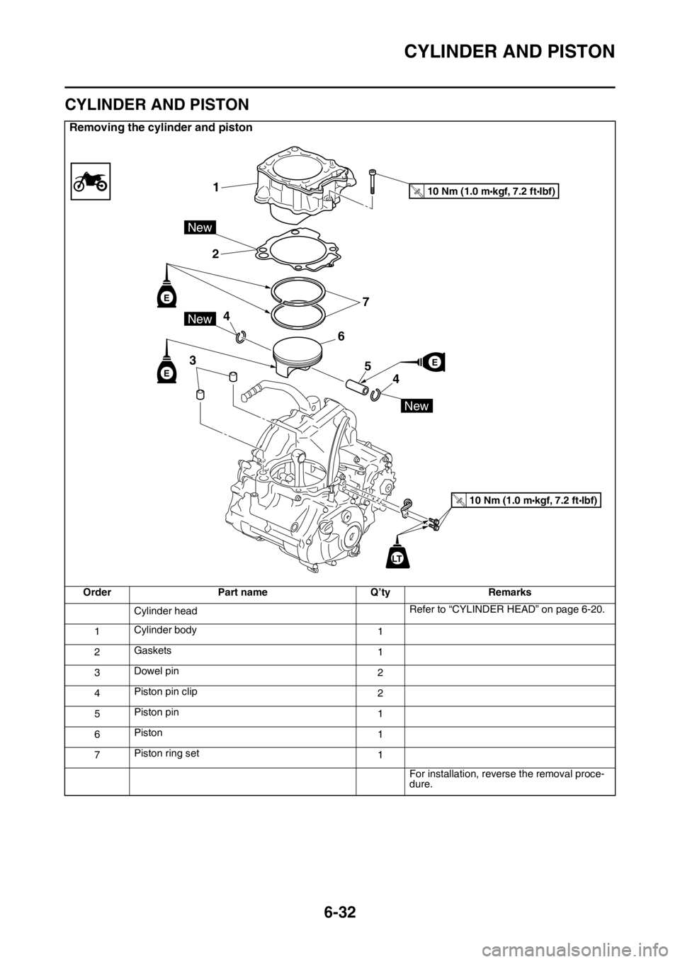
CYLINDER AND PISTON
Removing the cylinder and piston
Order Part name QŌĆÖty Remarks
Cylinder headRefer to ŌĆ£CYLINDER HEADŌĆØ on page 6-20.
1Cylinder body
1
2Gaskets
1
3Dowel pin
2
4Piston pin clip
2
5Piston pin
1
6Piston
1
7Piston ring set
1
For installation, reverse the removal proce-
dure.
1
2
3
4
4
5
6
7
10 Nm (1.0 mkgf, 7.2 ftIbf)T.R.
10 Nm (1.0 mkgf, 7.2 ftIbf)T.R.
E
E
New
New
New
LT
E
Page 262 of 432
CYLINDER AND PISTON
6-33
EAS2GBB257REMOVING THE PISTON
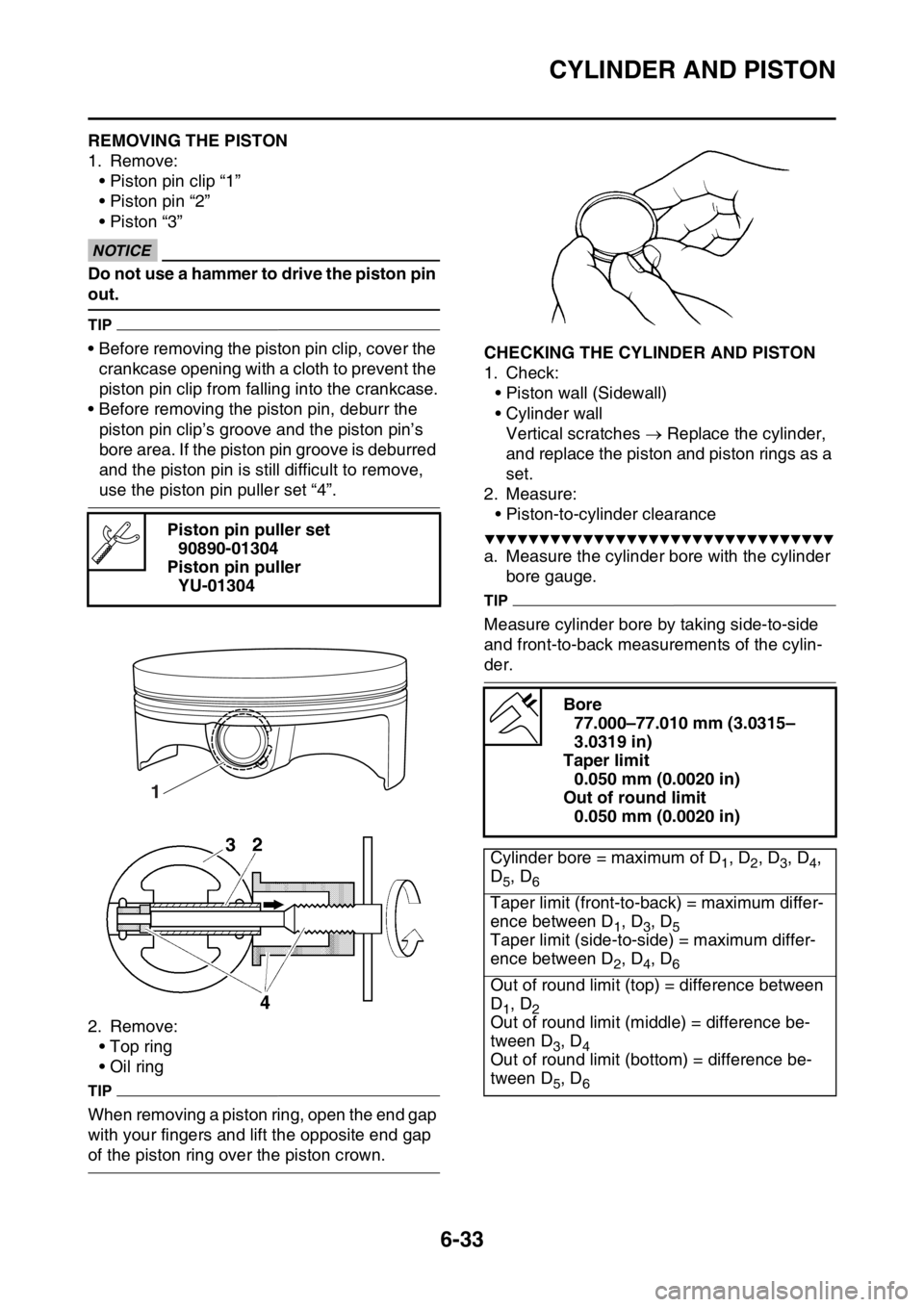
1. Remove:
ŌĆó Piston pin clip ŌĆ£1ŌĆØ
ŌĆó Piston pin ŌĆ£2ŌĆØ
ŌĆó Piston ŌĆ£3ŌĆØ
ECA
NOTICE
Do not use a hammer to drive the piston pin
out.
TIP
ŌĆó Before removing the piston pin clip, cover the
crankcase opening with a cloth to prevent the
piston pin clip from falling into the crankcase.
ŌĆó Before removing the piston pin, deburr the
piston pin clipŌĆÖs groove and the piston pinŌĆÖs
bore area. If the piston pin groove is deburred
and the piston pin is still difficult to remove,
use the piston pin puller set ŌĆ£4ŌĆØ.
2. Remove:
ŌĆó Top ring
ŌĆó Oil ring
TIP
When removing a piston ring, open the end gap
with your fingers and lift the opposite end gap
of the piston ring over the piston crown.
EAS2GBB258CHECKING THE CYLINDER AND PISTON
1. Check:
ŌĆó Piston wall (Sidewall)
ŌĆó Cylinder wall
Vertical scratches ’é« Replace the cylinder,
and replace the piston and piston rings as a
set.
2. Measure:
ŌĆó Piston-to-cylinder clearance
Ō¢╝Ō¢╝Ō¢╝Ō¢╝Ō¢╝Ō¢╝Ō¢╝Ō¢╝Ō¢╝Ō¢╝Ō¢╝Ō¢╝Ō¢╝Ō¢╝Ō¢╝Ō¢╝Ō¢╝Ō¢╝Ō¢╝Ō¢╝Ō¢╝Ō¢╝Ō¢╝Ō¢╝Ō¢╝Ō¢╝Ō¢╝Ō¢╝Ō¢╝Ō¢╝Ō¢╝Ō¢╝
a. Measure the cylinder bore with the cylinder
bore gauge.
TIP
Measure cylinder bore by taking side-to-side
and front-to-back measurements of the cylin-
der. Piston pin puller set
90890-01304
Piston pin puller
YU-01304
1
Bore
77.000ŌĆō77.010 mm (3.0315ŌĆō
3.0319 in)
Taper limit
0.050 mm (0.0020 in)
Out of round limit
0.050 mm (0.0020 in)
Cylinder bore = maximum of D
1, D2, D3, D4,
D
5, D6
Taper limit (front-to-back) = maximum differ-
ence between D
1, D3, D5Taper limit (side-to-side) = maximum differ-
ence between D
2, D4, D6
Out of round limit (top) = difference between
D
1, D2Out of round limit (middle) = difference be-
tween D
3, D4Out of round limit (bottom) = difference be-
tween D
5, D6
Page 263 of 432
CYLINDER AND PISTON
6-34
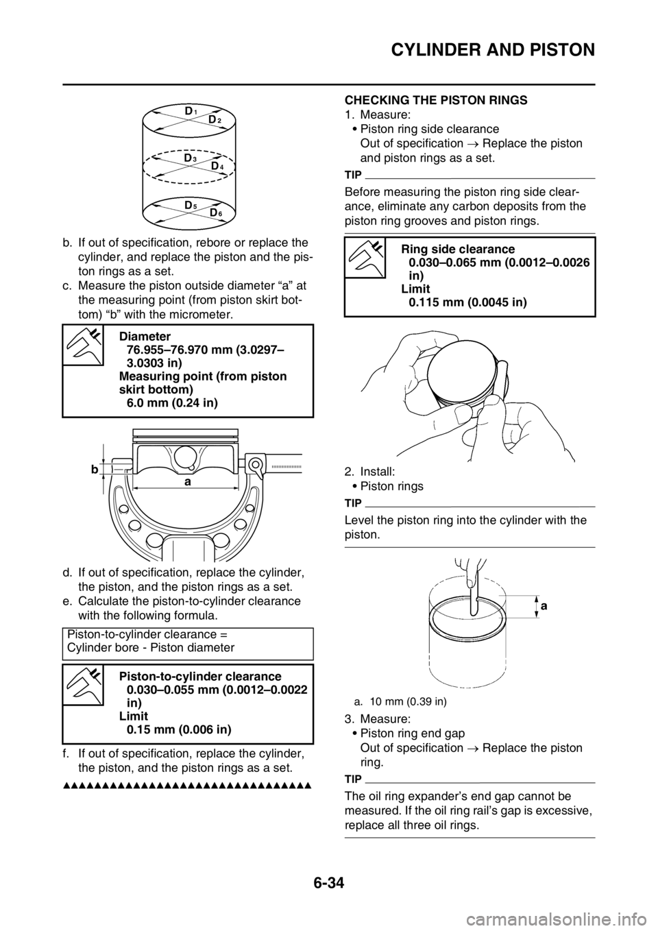
b. If out of specification, rebore or replace the
cylinder, and replace the piston and the pis-
ton rings as a set.
c. Measure the piston outside diameter ŌĆ£aŌĆØ at
the measuring point (from piston skirt bot-
tom) ŌĆ£bŌĆØ with the micrometer.
d. If out of specification, replace the cylinder,
the piston, and the piston rings as a set.
e. Calculate the piston-to-cylinder clearance
with the following formula.
f. If out of specification, replace the cylinder,
the piston, and the piston rings as a set.
Ō¢▓Ō¢▓Ō¢▓Ō¢▓Ō¢▓Ō¢▓Ō¢▓Ō¢▓Ō¢▓Ō¢▓Ō¢▓Ō¢▓Ō¢▓Ō¢▓Ō¢▓Ō¢▓Ō¢▓Ō¢▓Ō¢▓Ō¢▓Ō¢▓Ō¢▓Ō¢▓Ō¢▓Ō¢▓Ō¢▓Ō¢▓Ō¢▓Ō¢▓Ō¢▓Ō¢▓Ō¢▓
EAS2GBB259CHECKING THE PISTON RINGS
1. Measure:
ŌĆó Piston ring side clearance
Out of specification ’é« Replace the piston
and piston rings as a set.
TIP
Before measuring the piston ring side clear-
ance, eliminate any carbon deposits from the
piston ring grooves and piston rings.
2. Install:
ŌĆó Piston rings
TIP
Level the piston ring into the cylinder with the
piston.
3. Measure:
ŌĆó Piston ring end gap
Out of specification ’é« Replace the piston
ring.
TIP
The oil ring expanderŌĆÖs end gap cannot be
measured. If the oil ring railŌĆÖs gap is excessive,
replace all three oil rings. Diameter
76.955ŌĆō76.970 mm (3.0297ŌĆō
3.0303 in)
Measuring point (from piston
skirt bottom)
6.0 mm (0.24 in)
Piston-to-cylinder clearance =
Cylinder bore - Piston diameter
Piston-to-cylinder clearance
0.030ŌĆō0.055 mm (0.0012ŌĆō0.0022
in)
Limit
0.15 mm (0.006 in)
b
a
Ring side clearance
0.030ŌĆō0.065 mm (0.0012ŌĆō0.0026
in)
Limit
0.115 mm (0.0045 in)
a. 10 mm (0.39 in)
Page 264 of 432
CYLINDER AND PISTON
6-35
EAS2GBB260CHECKING THE PISTON PIN
1. Check:
ŌĆó Piston pin
Blue discoloration/grooves ’é« Replace the
piston pin and then check the lubrication
system.
2. Measure:
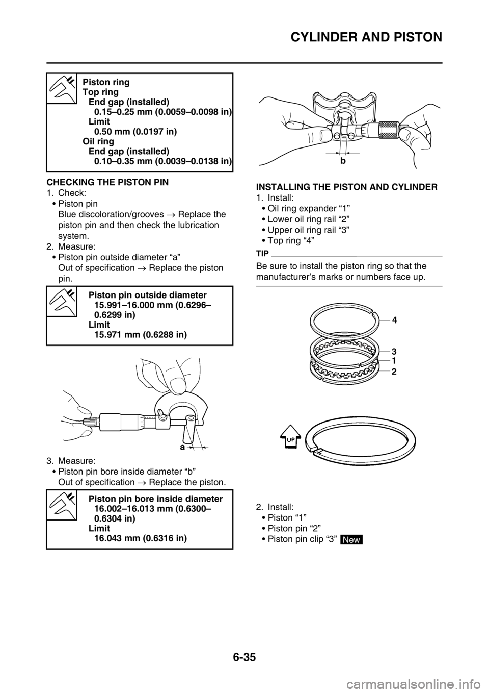
ŌĆó Piston pin outside diameter ŌĆ£aŌĆØ
Out of specification ’é« Replace the piston
pin.
3. Measure:
ŌĆó Piston pin bore inside diameter ŌĆ£bŌĆØ
Out of specification ’é« Replace the piston.EAS2GBB261INSTALLING THE PISTON AND CYLINDER
1. Install:
ŌĆó Oil ring expander ŌĆ£1ŌĆØ
ŌĆó Lower oil ring rail ŌĆ£2ŌĆØ
ŌĆó Upper oil ring rail ŌĆ£3ŌĆØ
ŌĆó Top ring ŌĆ£4ŌĆØ
TIP
Be sure to install the piston ring so that the
manufacturerŌĆÖs marks or numbers face up.
2. Install:
ŌĆó Piston ŌĆ£1ŌĆØ
ŌĆó Piston pin ŌĆ£2ŌĆØ
ŌĆó Piston pin clip ŌĆ£3ŌĆØ Piston ring
Top ring
End gap (installed)
0.15ŌĆō0.25 mm (0.0059ŌĆō0.0098 in)
Limit
0.50 mm (0.0197 in)
Oil ring
End gap (installed)
0.10ŌĆō0.35 mm (0.0039ŌĆō0.0138 in)
Piston pin outside diameter
15.991ŌĆō16.000 mm (0.6296ŌĆō
0.6299 in)
Limit
15.971 mm (0.6288 in)
Piston pin bore inside diameter
16.002ŌĆō16.013 mm (0.6300ŌĆō
0.6304 in)
Limit
16.043 mm (0.6316 in)
b
4
New
Page 265 of 432
CYLINDER AND PISTON
6-36
TIP
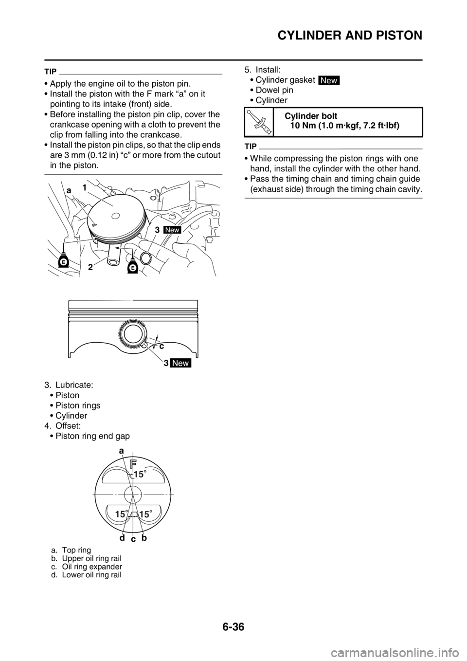
ŌĆó Apply the engine oil to the piston pin.
ŌĆó Install the piston with the F mark ŌĆ£aŌĆØ on it
pointing to its intake (front) side.
ŌĆó Before installing the piston pin clip, cover the
crankcase opening with a cloth to prevent the
clip from falling into the crankcase.
ŌĆó Install the piston pin clips, so that the clip ends
are 3 mm (0.12 in) ŌĆ£cŌĆØ or more from the cutout
in the piston.
3. Lubricate:
ŌĆóPiston
ŌĆó Piston rings
ŌĆó Cylinder
4. Offset:
ŌĆó Piston ring end gap5. Install:
ŌĆó Cylinder gasket
ŌĆó Dowel pin
ŌĆó Cylinder
TIP
ŌĆó While compressing the piston rings with one
hand, install the cylinder with the other hand.
ŌĆó Pass the timing chain and timing chain guide
(exhaust side) through the timing chain cavity.
a. Top ring
b. Upper oil ring rail
c. Oil ring expander
d. Lower oil ring rail
1
3
2 a
3 c
a
db
c15
15
15
Cylinder bolt
10 Nm (1.0 m┬Ękgf, 7.2 ft┬Ęlbf)
New
T R..
Page 266 of 432
ELECTRIC STARTER
6-37
EAS2GBB262
ELECTRIC STARTER
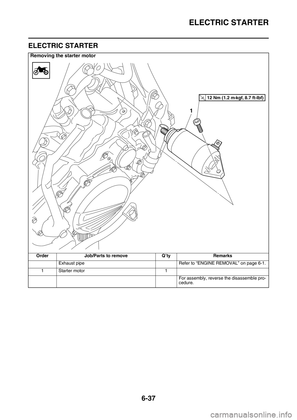
Removing the starter motor
Order Job/Parts to remove QŌĆÖty Remarks
Exhaust pipe Refer to ŌĆ£ENGINE REMOVALŌĆØ on page 6-1.
1 Starter motor 1
For assembly, reverse the disassemble pro-
cedure.
1
12 Nm (1.2 m kgf, 8.7 ft Ibf)T.R.
Page 267 of 432
ELECTRIC STARTER
6-38
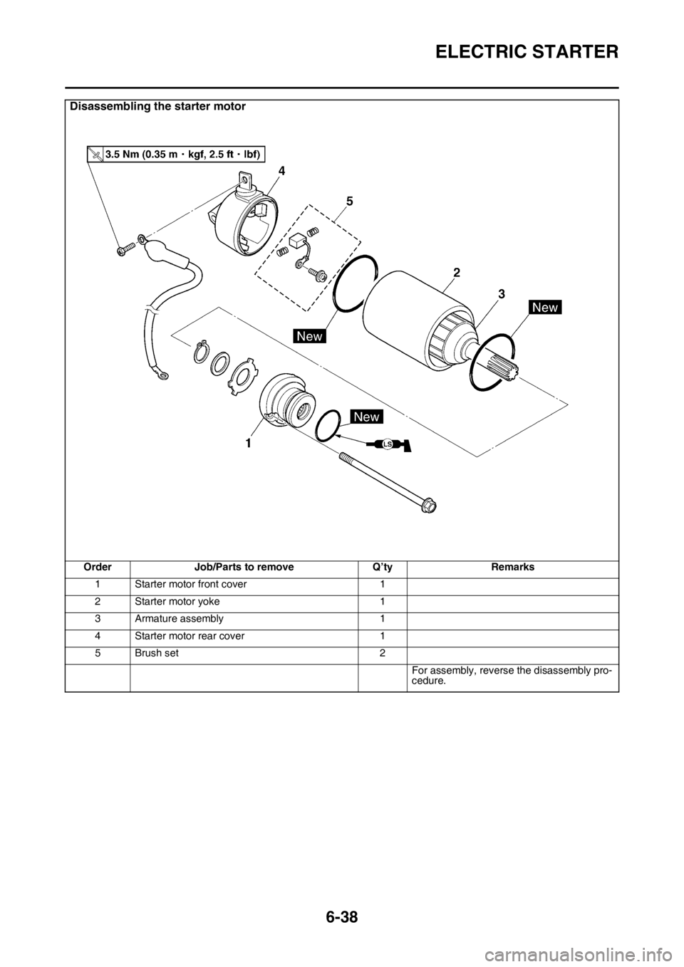
Disassembling the starter motor
Order Job/Parts to remove QŌĆÖty Remarks
1 Starter motor front cover 1
2 Starter motor yoke 1
3 Armature assembly 1
4 Starter motor rear cover 1
5 Brush set 2
For assembly, reverse the disassembly pro-
cedure.
Page 268 of 432
ELECTRIC STARTER
6-39
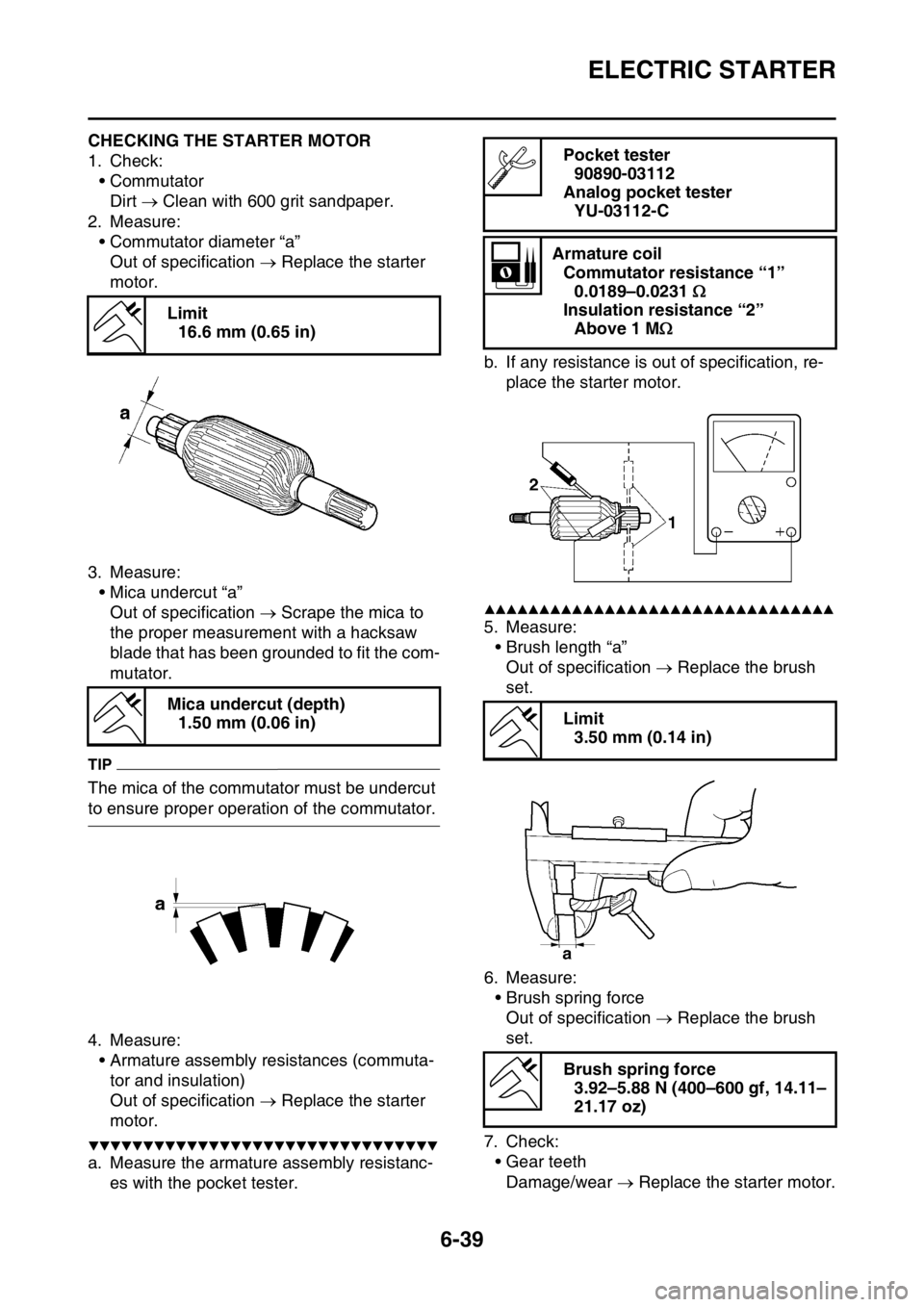
EAS2GBB263CHECKING THE STARTER MOTOR
1. Check:
ŌĆóCommutator
Dirt ’é« Clean with 600 grit sandpaper.
2. Measure:
ŌĆó Commutator diameter ŌĆ£aŌĆØ
Out of specification ’é« Replace the starter
motor.
3. Measure:
ŌĆó Mica undercut ŌĆ£aŌĆØ
Out of specification ’é« Scrape the mica to
the proper measurement with a hacksaw
blade that has been grounded to fit the com-
mutator.
TIP
The mica of the commutator must be undercut
to ensure proper operation of the commutator.
4. Measure:
ŌĆó Armature assembly resistances (commuta-
tor and insulation)
Out of specification ’é« Replace the starter
motor.
Ō¢╝Ō¢╝Ō¢╝Ō¢╝Ō¢╝Ō¢╝Ō¢╝Ō¢╝Ō¢╝Ō¢╝Ō¢╝Ō¢╝Ō¢╝Ō¢╝Ō¢╝Ō¢╝Ō¢╝Ō¢╝Ō¢╝Ō¢╝Ō¢╝Ō¢╝Ō¢╝Ō¢╝Ō¢╝Ō¢╝Ō¢╝Ō¢╝Ō¢╝Ō¢╝Ō¢╝Ō¢╝
a. Measure the armature assembly resistanc-
es with the pocket tester.b. If any resistance is out of specification, re-
place the starter motor.
Ō¢▓Ō¢▓Ō¢▓Ō¢▓Ō¢▓Ō¢▓Ō¢▓Ō¢▓Ō¢▓Ō¢▓Ō¢▓Ō¢▓Ō¢▓Ō¢▓Ō¢▓Ō¢▓Ō¢▓Ō¢▓Ō¢▓Ō¢▓Ō¢▓Ō¢▓Ō¢▓Ō¢▓Ō¢▓Ō¢▓Ō¢▓Ō¢▓Ō¢▓Ō¢▓Ō¢▓Ō¢▓
5. Measure:
ŌĆó Brush length ŌĆ£aŌĆØ
Out of specification ’é« Replace the brush
set.
6. Measure:
ŌĆó Brush spring force
Out of specification ’é« Replace the brush
set.
7. Check:
ŌĆó Gear teeth
Damage/wear ’é« Replace the starter motor. Limit
16.6 mm (0.65 in)
Mica undercut (depth)
1.50 mm (0.06 in)
Pocket tester
90890-03112
Analog pocket tester
YU-03112-C
Armature coil
Commutator resistance ŌĆ£1ŌĆØ
0.0189ŌĆō0.0231 ’üŚ
Insulation resistance ŌĆ£2ŌĆØ
Above 1 M’üŚ
Limit
3.50 mm (0.14 in)
Brush spring force
3.92ŌĆō5.88 N (400ŌĆō600 gf, 14.11ŌĆō
21.17 oz)
Page 269 of 432
ELECTRIC STARTER
6-40
8. Check:
ŌĆó Oil seal
Damage/wear ’é« Replace the defective part
(s).
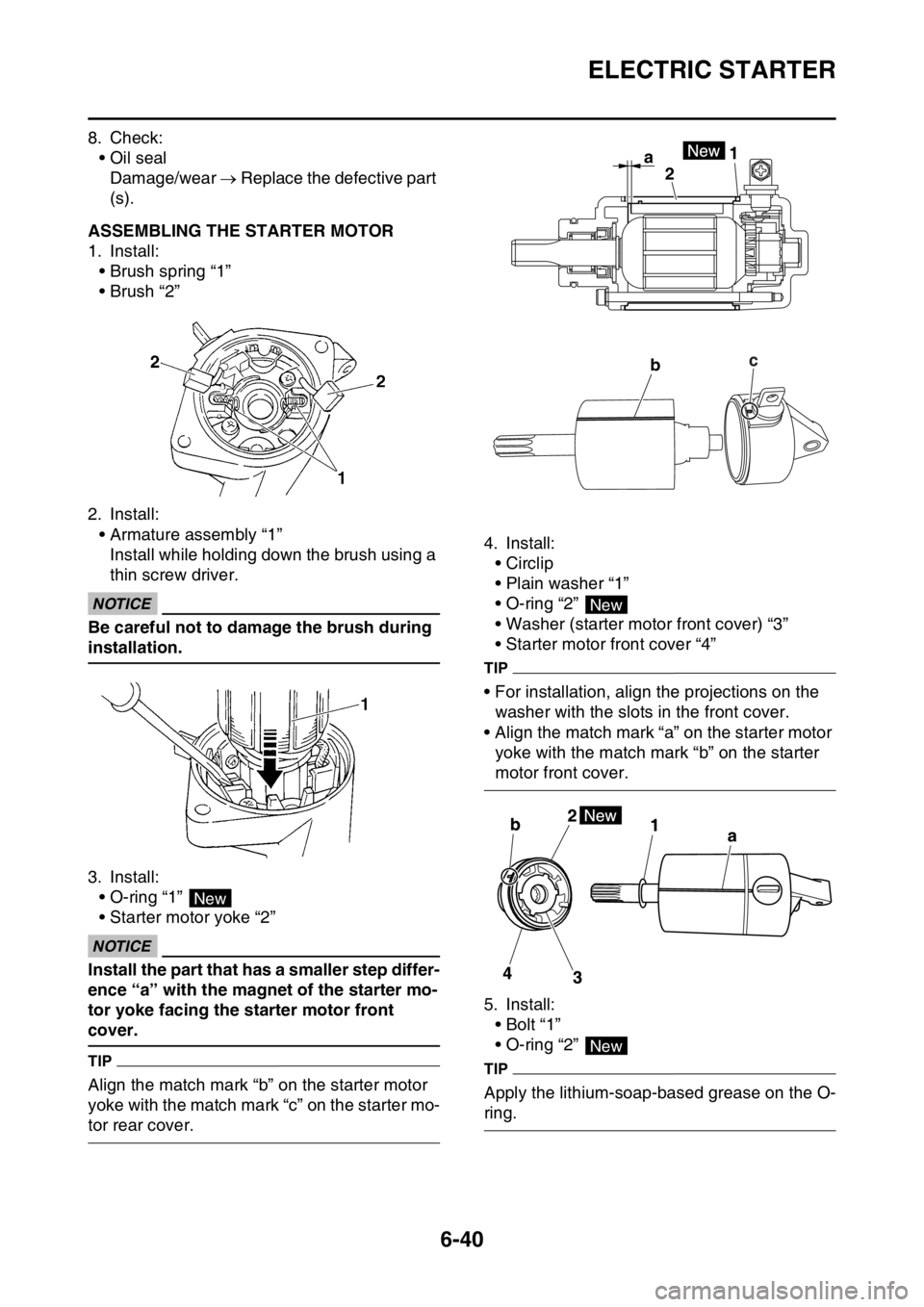
EAS2GBB264ASSEMBLING THE STARTER MOTOR
1. Install:
ŌĆó Brush spring ŌĆ£1ŌĆØ
ŌĆó Brush ŌĆ£2ŌĆØ
2. Install:
ŌĆó Armature assembly ŌĆ£1ŌĆØ
Install while holding down the brush using a
thin screw driver.
ECA
NOTICE
Be careful not to damage the brush during
installation.
3. Install:
ŌĆó O-ring ŌĆ£1ŌĆØ
ŌĆó Starter motor yoke ŌĆ£2ŌĆØ
ECA
NOTICE
Install the part that has a smaller step differ-
ence ŌĆ£aŌĆØ with the magnet of the starter mo-
tor yoke facing the starter motor front
cover.
TIP
Align the match mark ŌĆ£bŌĆØ on the starter motor
yoke with the match mark ŌĆ£cŌĆØ on the starter mo-
tor rear cover.4. Install:
ŌĆó Circlip
ŌĆóPlain washer ŌĆ£1ŌĆØ
ŌĆó O-ring ŌĆ£2ŌĆØ
ŌĆó Washer (starter motor front cover) ŌĆ£3ŌĆØ
ŌĆó Starter motor front cover ŌĆ£4ŌĆØ
TIP
ŌĆó For installation, align the projections on the
washer with the slots in the front cover.
ŌĆó Align the match mark ŌĆ£aŌĆØ on the starter motor
yoke with the match mark ŌĆ£bŌĆØ on the starter
motor front cover.
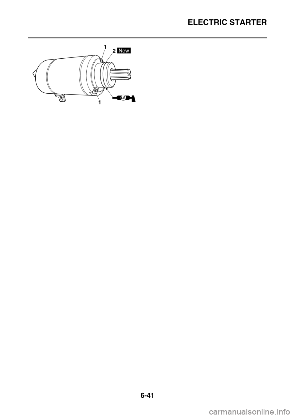
5. Install:
ŌĆóBolt ŌĆ£1ŌĆØ
ŌĆó O-ring ŌĆ£2ŌĆØ
TIP
Apply the lithium-soap-based grease on the O-
ring.
New
a1
2
bc
New
New
Page 270 of 432
ELECTRIC STARTER
6-41