YAMAHA WR 250F 2017 Owners Manual
WR 250F 2017
YAMAHA
YAMAHA
https://www.carmanualsonline.info/img/51/52286/w960_52286-0.png
YAMAHA WR 250F 2017 Owners Manual
Trending: remove seats, coolant temperature, cooling, air condition, weight, service interval, check transmission fluid
Page 391 of 432
FUEL INJECTION SYSTEM
9-55
TIP
Before troubleshooting, disconnect the starter motor lead from the starter relay.
Fault code No. Er-4
ItemRegistered data cannot be received from the Yamaha diagnos-
tic tool.
Fail-safe systemAble to start engine
Able to drive vehicle
Diagnostic code No.—
Diagnostic tool display—
Procedure—
ItemProbable cause of malfunc-
tion and checkMaintenance jobConfirmation of service
completion
1 Connection of Yamaha diag-
nostic tool coupler.
Check the locking condition
of the coupler.
Disconnect the coupler and
check the pins (bent or bro-
ken terminals and locking
condition of the pins).Improperly connected
Connect the coupler securely
or repair/replace the wire har-
ness.Push the start switch.
Fault code number is not dis-
played Service is finished.
Fault code number is dis-
played Go to item 2.
2 Connection of wire harness
ECU coupler.
Check the locking condition
of the coupler.
Disconnect the coupler and
check the pins (bent or bro-
ken terminals and locking
condition of the pins).Improperly connected
Connect the coupler securely
or repair/replace the wire har-
ness.Push the start switch.
Fault code number is not dis-
played Service is finished.
Fault code number is dis-
played Go to item 3.
3 Wire harness continuity. Open or short circuit Re-
place the wire harness.
light green–light greenPush the start switch.
Fault code number is not dis-
played Service is finished.
Fault code number is dis-
played Go to item 4.
4 Yamaha diagnostic tool mal-
function.Replace the Yamaha diag-
nostic tool.Push the start switch.
Fault code number is not dis-
played Service is finished.
Fault code number is dis-
played Go to item 5.
5 Malfunction in ECU. Replace the ECU.
Page 392 of 432
FUEL PUMP SYSTEM
9-56
EAS2GBB378
FUEL PUMP SYSTEM
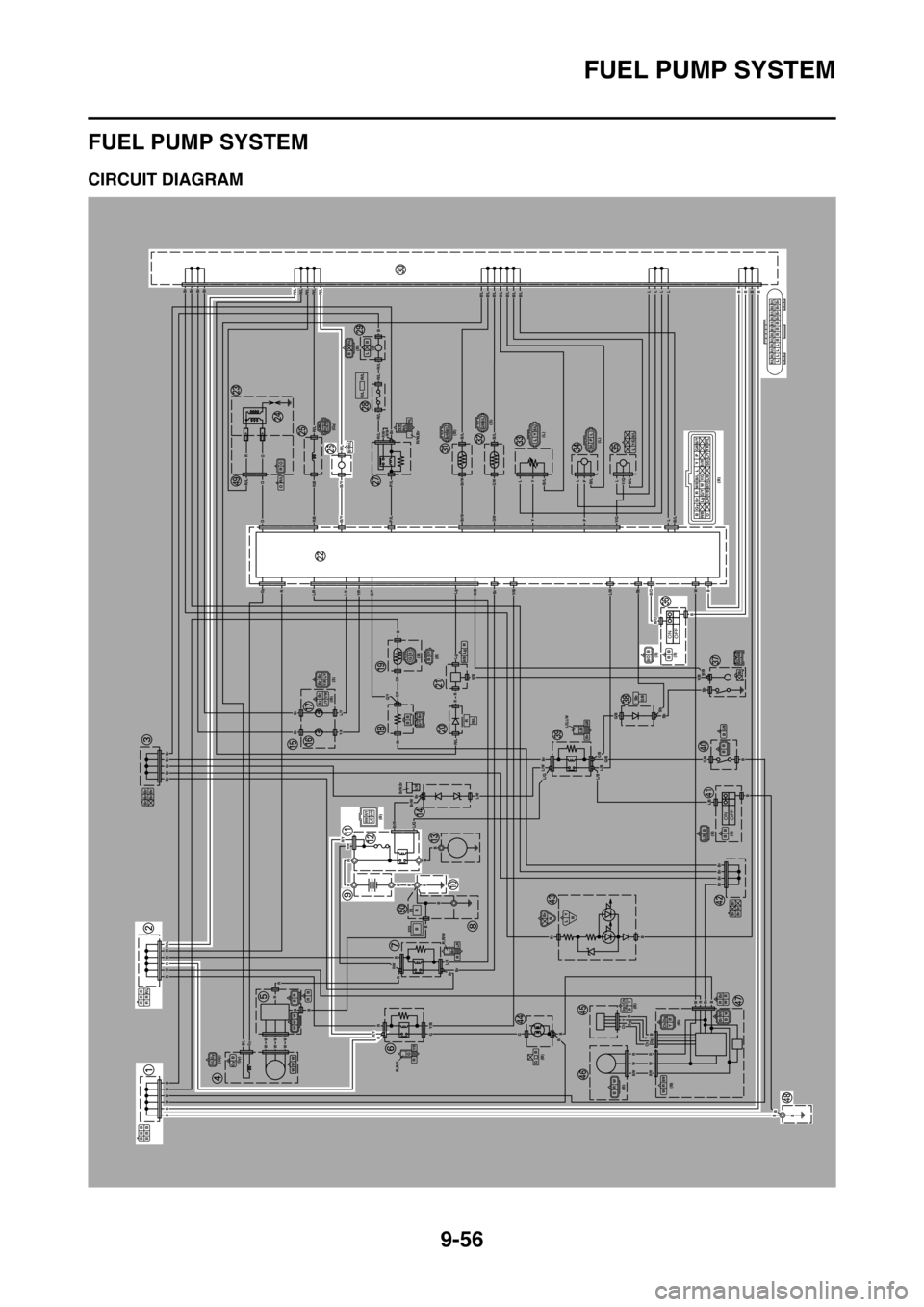
EAS2GBB379CIRCUIT DIAGRAM
ONOFF
ONOFF
BBB
BBB
RRR
RRR/L
Br Br Br
Br Br
(Gy)
(Gy)B/LGyWW WB Gy
B R
WW W
BR
R,R/Y
G
R
Y/B
R,R/W
Br
RL/R
(B)R/YR/WBr/WL/G
Br/W,BrL/W
(B) (B)Br BrL/Y Y/R
G/YBrBB
BrBrL/YY/W
(B)(B)BB GG/Y
RR/L
R Lg
W/B
(B) BGyBr RW/BB/LLYP
G/WB/Y
R/BLgG/YW
Br/W
OL/RY/BB/OL/BSbY/R L/Y P/L
Y/G
(Gy)R/L R/BR/LB/Y
R/WR/L
R/W,BrP/L
R/L R/L
(B)
(B)
(B)
(L)
(L)(B) BR/LLBR/L R/L R/L R/L R/L B/L B/L B/L B/L B/L B/L B/LL L L LBBBB
Br Br Br Br
B/LBr/W
B/LG/WLYB/L
B/LPLB/LY/GL
(B)
(B)B/OBB BSbW/B
Sb
SbG/B
L/G,L/WL/BBrG/BG/BB
BB
(B)
(B)L/BBB B
Br Br
Br BrBr
BB LY
(B)
(B)
(B)
(B)
(B)
GB
Ch Dg
Y B
BRW
Br R
B W
B/WR W
Ch DgYBBrR/WBW
R O
OR/L
B
B
BBBBBB
RRRRRR/L
BrBrBrBrBr
Br
Br
BrBrBrBrR/LR/LR/LR/LR/L
B
LLLP
PL
Y
Y
RR
Br
R/LR/L
R/L
P/L
P/L
R/L
R/L
R/LR/B
R/B
L/RL/Y
L/Y
Y/R
Y/R
G/Y
G/YG/Y
G/Y
B/Y
B/Y
R/LB/LB/L
B/LB/LB/LY/G
Y/GB/L
B/OL/BY/BW/B
W/B
G/B
L/B
W/BW/B
L/BL/BL/GL/W
L/W
L/R
Br/W
Br/W
R/W
R/W
R/Y
R/Y
G/BG/B
G/B
B/O
B/LB/LB/LB/LB/LB/LB/L
G/W
G/W
Br/W
Br/W
R/WR/WBr
O
O
OR
RGy
LLLLBBBB
B
B
B
B
BBB
B
B
RRWW
Y
Y
Dg
Dg
Ch
Ch
RW
BrBrBrBr
Br
B
W
Sb
SbSb
SbBr
Br
B
Br
Lg
Lg
R/L
R
R
RR
Gy
BB
WWWWWW
R
RRGGBB
B
Y/B
RB
BB
B
B
Br
Br
Br
B
L/G
B/L
B/WB/W
B
Page 393 of 432
FUEL PUMP SYSTEM
9-57
1. Joint connector
2. Joint connector
9. Battery
10.Frame ground
11.Starter relay
12.Main fuse
22.ECU (engine control unit)
26.Fuel pump
30.Joint connector
36.Engine stop switch
48.Frame ground
Page 394 of 432
FUEL PUMP SYSTEM
9-58
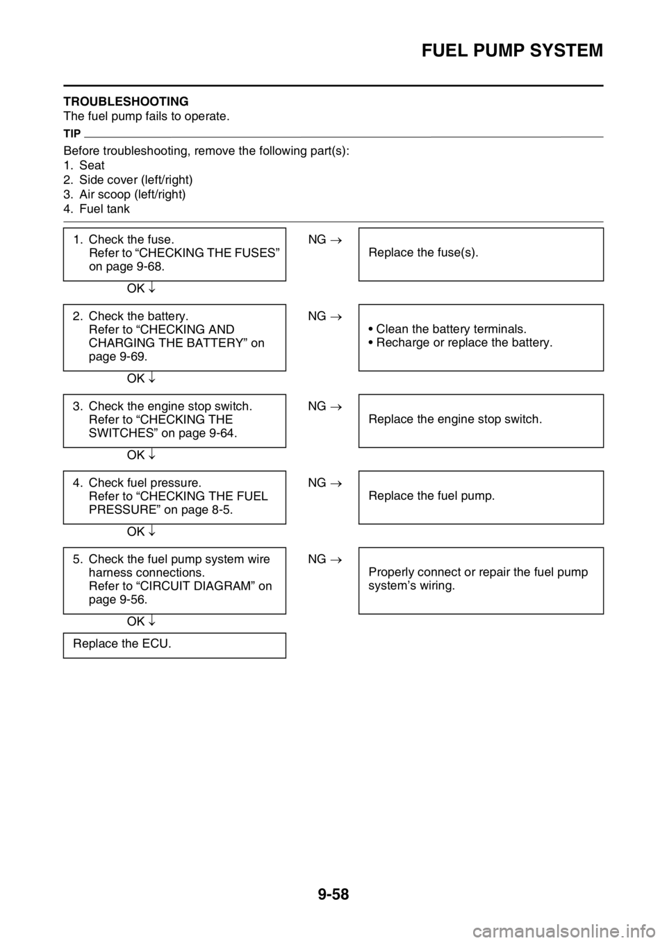
EAS2GBB380TROUBLESHOOTING
The fuel pump fails to operate.
TIP
Before troubleshooting, remove the following part(s):
1. Seat
2. Side cover (left/right)
3. Air scoop (left/right)
4. Fuel tank
1. Check the fuse.
Refer to “CHECKING THE FUSES”
on page 9-68.NG
Replace the fuse(s).
OK
2. Check the battery.
Refer to “CHECKING AND
CHARGING THE BATTERY” on
page 9-69.NG
• Clean the battery terminals.
• Recharge or replace the battery.
OK
3. Check the engine stop switch.
Refer to “CHECKING THE
SWITCHES” on page 9-64.NG
Replace the engine stop switch.
OK
4. Check fuel pressure.
Refer to “CHECKING THE FUEL
PRESSURE” on page 8-5.NG
Replace the fuel pump.
OK
5. Check the fuel pump system wire
harness connections.
Refer to “CIRCUIT DIAGRAM” on
page 9-56.NG
Properly connect or repair the fuel pump
system’s wiring.
OK
Replace the ECU.
Page 395 of 432
Page 396 of 432
ELECTRICAL COMPONENTS
9-60
EAS2GBB381
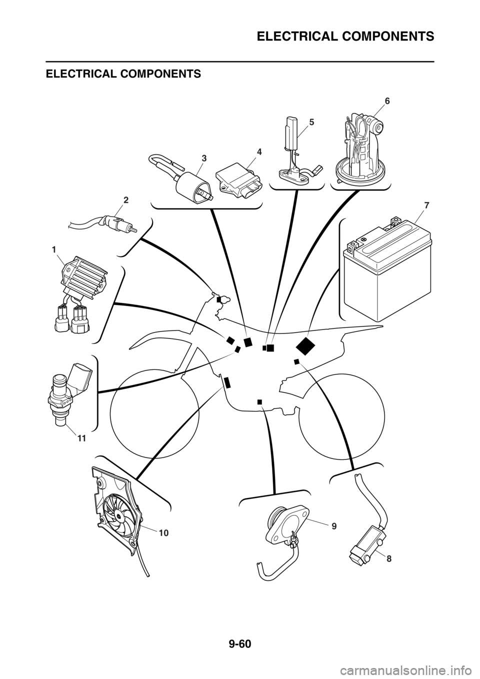
ELECTRICAL COMPONENTS
EAS2GBB382
910
11
1
3
2
456
7
8
Page 397 of 432
ELECTRICAL COMPONENTS
9-61
1. Rectifier/regulator
2. Clutch switch
3. Ignition coil
4. ECU (engine control unit)
5. Fuel sender
6. Fuel pump
7. Battery
8. Resistor
9. Neutral switch
10.Radiator fan motor
11.Injector
Page 398 of 432
ELECTRICAL COMPONENTS
9-62
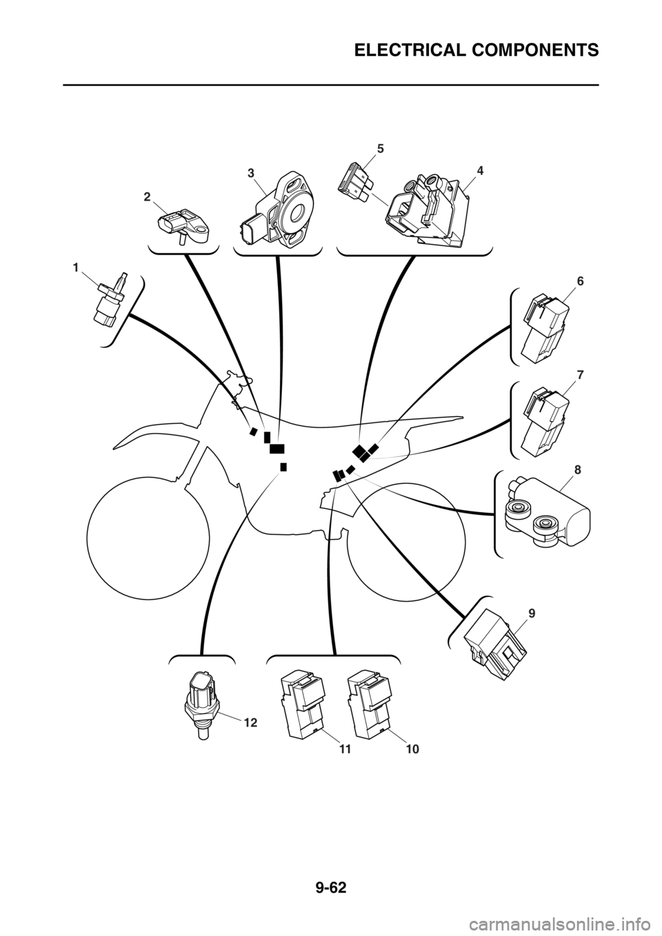
12
1110
2
3
1
6
7
4
5
8
9
Page 399 of 432
ELECTRICAL COMPONENTS
9-63
1. Intake air temperature sensor
2. Intake air pressure sensor
3. Throttle position sensor
4. Starter relay
5. Main fuse
6. Headlight relay
7. Starting circuit cut-off relay
8. Lean angle sensor
9. Radiator fan motor fuse
10.Radiator fan motor relay
11.Main relay
12.Coolant temperature sensor
Page 400 of 432
ELECTRICAL COMPONENTS
9-64
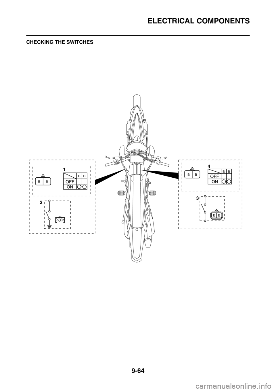
EAS2GBB383CHECKING THE SWITCHES
4
1
3
2
B B
Sb
B B
B BB
B BB
Trending: seats, ESP, octane, check engine, oil, suspension, maintenance schedule


