YAMAHA WR 400F 2000 Manual Online
Manufacturer: YAMAHA, Model Year: 2000, Model line: WR 400F, Model: YAMAHA WR 400F 2000Pages: 654, PDF Size: 60.12 MB
Page 81 of 654
2 - 10
SPEC
MAINTENANCE SPECIFICATIONS
Item Standard
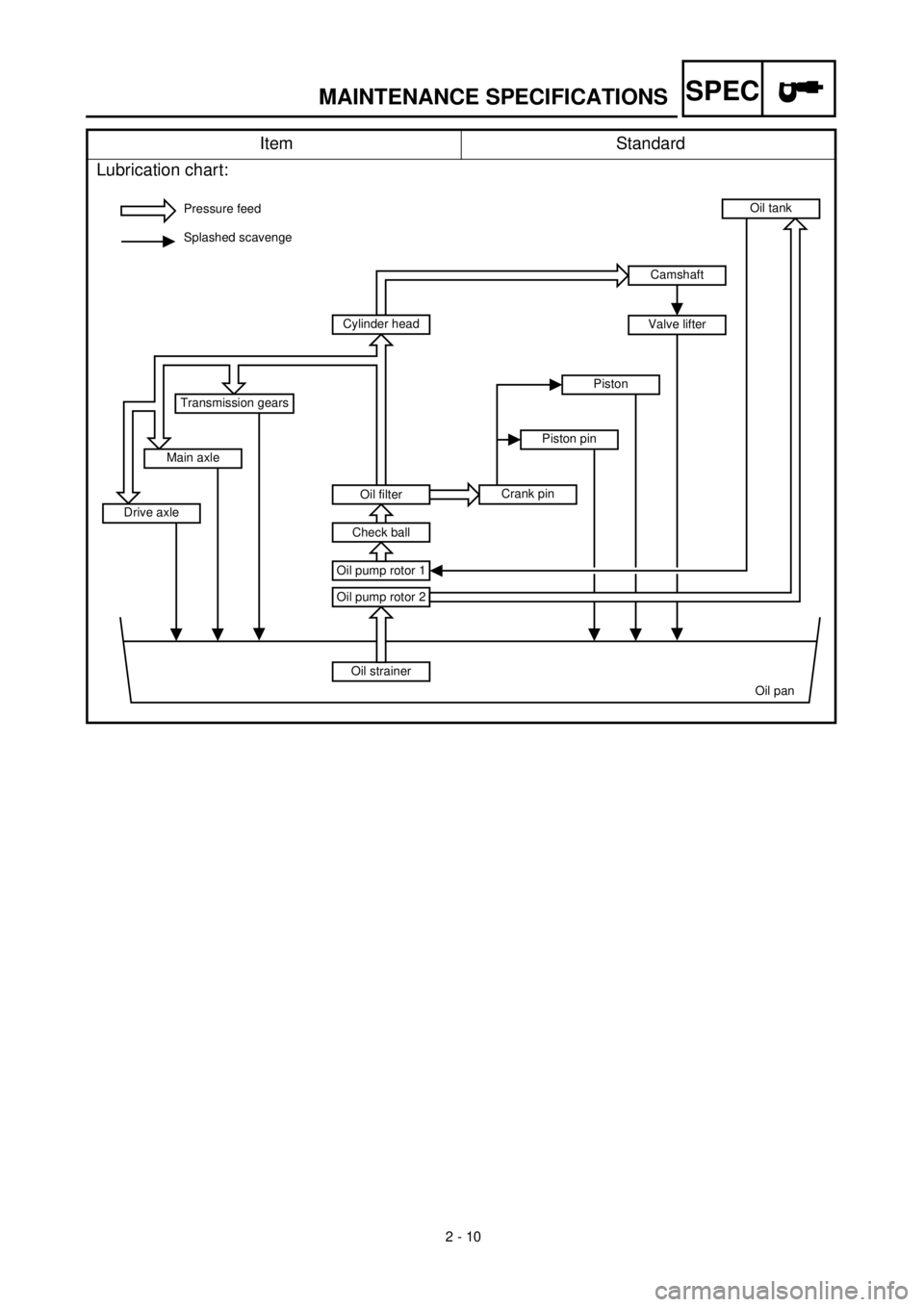
Lubrication chart:
Pressure feed
Splashed scavenge
Oil strainer
Oil pan Oil pump rotor 2
Oil pump rotor 1
Oil tank
Oil filter
Check ball
Cylinder head
Crank pinPiston pinPiston
Drive axleMain axleTransmission gears
Camshaft
Valve lifter
Page 82 of 654
2 - 11
SPEC
MAINTENANCE SPECIFICATIONS
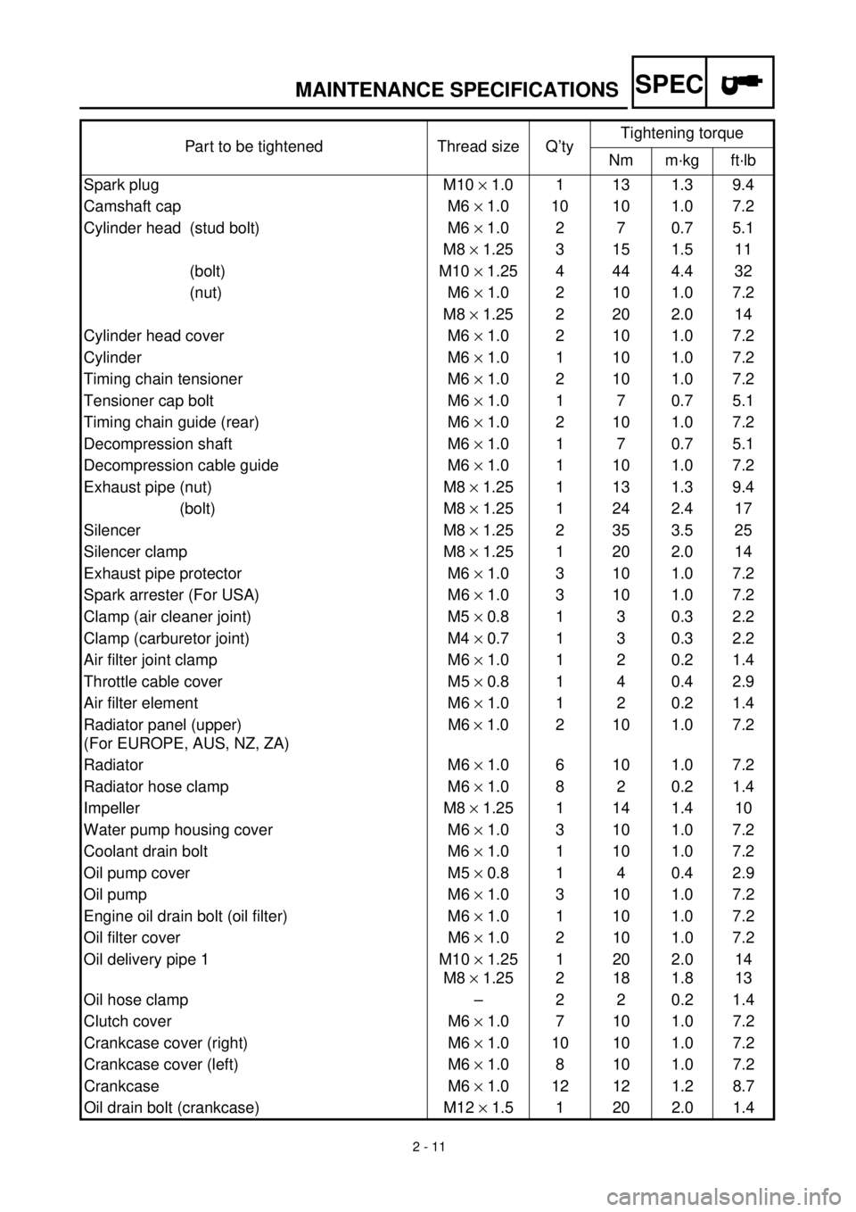
Part to be tightened Thread size Q’tyTightening torque
Nm m·kg ft·lb
Spark plug M10
´
1.0 1 13 1.3 9.4
Camshaft cap M6
´
1.0 10 10 1.0 7.2
Cylinder head (stud bolt) M6
´
1.0 2 7 0.7 5.1
M8
´
1.25 3 15 1.5 11
(bolt) M10
´
1.25 4 44 4.4 32
(nut) M6
´
1.0 2 10 1.0 7.2
M8
´
1.25 2 20 2.0 14
Cylinder head cover M6
´
1.0 2 10 1.0 7.2
Cylinder M6
´
1.0 1 10 1.0 7.2
Timing chain tensioner M6
´
1.0 2 10 1.0 7.2
Tensioner cap bolt M6
´
1.0 1 7 0.7 5.1
Timing chain guide (rear) M6
´
1.0 2 10 1.0 7.2
Decompression shaft M6
´
1.0 1 7 0.7 5.1
Decompression cable guide M6
´
1.0 1 10 1.0 7.2
Exhaust pipe (nut) M8
´
1.25 1 13 1.3 9.4
(bolt) M8
´
1.25 1 24 2.4 17
Silencer M8
´
1.25 2 35 3.5 25
Silencer clamp M8
´
1.25 1 20 2.0 14
Exhaust pipe protector M6
´
1.0 3 10 1.0 7.2
Spark arrester (For USA) M6
´
1.0 3 10 1.0 7.2
Clamp (air cleaner joint) M5
´
0.8 1 3 0.3 2.2
Clamp (carburetor joint) M4
´
0.7 1 3 0.3 2.2
Air filter joint clamp M6
´
1.0 1 2 0.2 1.4
Throttle cable cover M5
´
0.8 1 4 0.4 2.9
Air filter element M6
´
1.0 1 2 0.2 1.4
Radiator panel (upper)
(For EUROPE, AUS, NZ, ZA)M6
´
1.0 2 10 1.0 7.2
Radiator M6
´
1.0 6 10 1.0 7.2
Radiator hose clamp M6
´
1.0 8 2 0.2 1.4
Impeller M8
´
1.25 1 14 1.4 10
Water pump housing cover M6
´
1.0 3 10 1.0 7.2
Coolant drain bolt M6
´
1.0 1 10 1.0 7.2
Oil pump cover M5 ´ 0.8 1 4 0.4 2.9
Oil pump M6 ´ 1.0 3 10 1.0 7.2
Engine oil drain bolt (oil filter) M6 ´ 1.0 1 10 1.0 7.2
Oil filter cover M6 ´ 1.0 2 10 1.0 7.2
Oil delivery pipe 1 M10 ´ 1.25
M8 ´ 1.251
220
182.0
1.814
13
Oil hose clamp – 2 2 0.2 1.4
Clutch cover M6 ´ 1.0 7 10 1.0 7.2
Crankcase cover (right) M6 ´ 1.0 10 10 1.0 7.2
Crankcase cover (left) M6 ´ 1.0 8 10 1.0 7.2
Crankcase M6 ´ 1.0 12 12 1.2 8.7
Oil drain bolt (crankcase) M12 ´ 1.5 1 20 2.0 1.4
Page 83 of 654
2 - 12
SPECMAINTENANCE SPECIFICATIONS
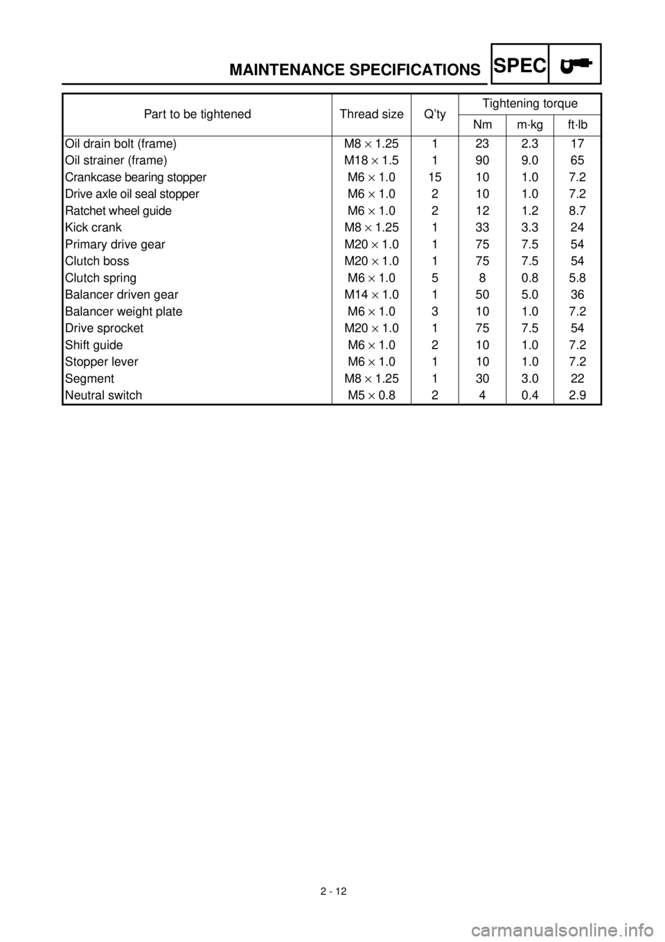
Oil drain bolt (frame) M8 ´ 1.25 1 23 2.3 17
Oil strainer (frame) M18 ´ 1.5 1 90 9.0 65
Crankcase bearing stopper M6 ´ 1.0 15 10 1.0 7.2
Drive axle oil seal stopper M6 ´ 1.0 2 10 1.0 7.2
Ratchet wheel guide M6 ´ 1.0 2 12 1.2 8.7
Kick crank M8 ´ 1.25 1 33 3.3 24
Primary drive gear M20 ´ 1.0 1 75 7.5 54
Clutch boss M20 ´ 1.0 1 75 7.5 54
Clutch spring M6 ´ 1.0 5 8 0.8 5.8
Balancer driven gear M14 ´ 1.0 1 50 5.0 36
Balancer weight plate M6 ´ 1.0 3 10 1.0 7.2
Drive sprocket M20 ´ 1.0 1 75 7.5 54
Shift guide M6 ´ 1.0 2 10 1.0 7.2
Stopper lever M6 ´ 1.0 1 10 1.0 7.2
Segment M8 ´ 1.25 1 30 3.0 22
Neutral switch M5 ´ 0.8 2 4 0.4 2.9 Part to be tightened Thread size Q’tyTightening torque
Nm m·kg ft·lb
Page 84 of 654

2 - 13
SPECMAINTENANCE SPECIFICATIONS
EC212201
CHASSIS
Item Standard Limit
Steering system:
Steering bearing type Taper roller bearing ----
Front suspension: USA, CDN
AUS, NZ, ZAEUROPE
Front fork travel 300 mm
(11.8 in)¬----
Fork spring free length 460 mm
(18.1 in)¬455 mm (17.9 in)
Spring rate, STD K = 4.6 N/mm
(0.46 kg/mm,
25.8 lb/in)K = 4.2 N/mm
(0.42 kg/mm,
23.5 lb/in)----
Optional spring/spacer Yes¬----
Oil capacity 573 cm
3
(20.2 lmp oz,
19.4 US oz) 583 cm3
(20.5 lmp oz,
19.7 US oz)----
Oil level 135 mm
(5.31 in)125 mm
(4.92 in)----
(From top of outer tube with inner
tube and damper rod fully com-
pressed without spring.)80 ~ 150 mm
(3.15 ~ 5.91 in)¬----
Oil grade Suspension oil
“01”¬----
Inner tube outer diameter 46 mm (1.81 in)¬----
Front fork top end 5 mm
(0.20 in)Zero mm
(Zero in)----
Rear suspension: USA, CDN,
AUS, NZ, ZAEUROPE
Shock absorber travel 132 mm
(5.20 in)¬----
Spring free length 260 mm
(10.24 in)¬----
Fitting length 245 mm
(9.65 in)244 mm
(9.61 in)----
(9.53 ~ 10.24 in)¬----
Spring rate, STD K = 50.0 N/mm
(5.00 kg/mm,
280.0 lb/in)K = 48.0 N/mm
(4.80 kg/mm,
268.8 lb/in)----
Optional spring Yes¬----
Enclosed gas pressure 1,000 kPa
(10 kg/cm
2,
142 psi)¬----
Swingarm:
Swingarm free play limit
End ---- 1.0 mm (0.04 in)
Page 85 of 654

2 - 14
SPECMAINTENANCE SPECIFICATIONS
Wheel:
Front wheel type Spoke wheel ----
Rear wheel type Spoke wheel ----
Front rim size/material 21 ´ 1.60/Aluminum ----
Rear rim size/material 18 ´ 2.15/Aluminum ----
Rim runout limit
Radial ---- 2.0 mm (0.08 in)
Lateral ---- 2.0 mm (0.08 in)
Drive chain:
Type/manufacturer 520VM/DAIDO ----
Number of links 113 links + joint ----
Chain slack 40 ~ 50 mm (1.6 ~ 2.0 in) ----
Chain length (10 links) ----150.1 mm (5.91 in)
Front disc brake:
Disc outside diameter ´ Thickness 245 ´ 3.0 mm (9.65 ´ 0.12 in) 245 ´ 2.5 mm
(9.65 ´ 0.08 in)
Deflection limit ----0.15 mm (0.006 in)
Pad thickness 4.4 mm (0.17 in) 1 mm (0.04 in)
Master cylinder inside dia. 11.0 mm (0.433 in) ----
Caliper cylinder inside dia. 27.0 mm (1.063 in) ´ 2 ----
Brake fluid type DOT #4 ----
Rear disc brake:
Disc outside diameter ´ Thickness 240 ´ 4.0 mm (9.45 ´ 0.16 in) 240 ´ 3.5 mm
(9.45 ´ 0.14 in)
Deflection limit ----0.15 mm (0.006 in)
Pad thickness 6.4 mm (0.25 in) 1.0 mm (0.04 in)
Master cylinder inside dia. 14.0 mm (0.551 in) ----
Caliper cylinder inside dia. 27.0 mm (1.063 in) ´ 1 ----
Brake fluid type DOT #4 ----
Brake lever and brake pedal:
Brake lever position 82.5 mm (3.25 in) ----
Brake pedal height
(vertical height below footrest top)5 mm (0.20 in) ----
Clutch lever free play (at lever pivot) 2 ~ 4 mm (0.08 ~ 0.16 in) ----
Throttle grip free play 3 ~ 5 mm (0.12 ~ 0.20 in) ----Item Standard Limit
Page 86 of 654
2 - 15
SPECMAINTENANCE SPECIFICATIONS
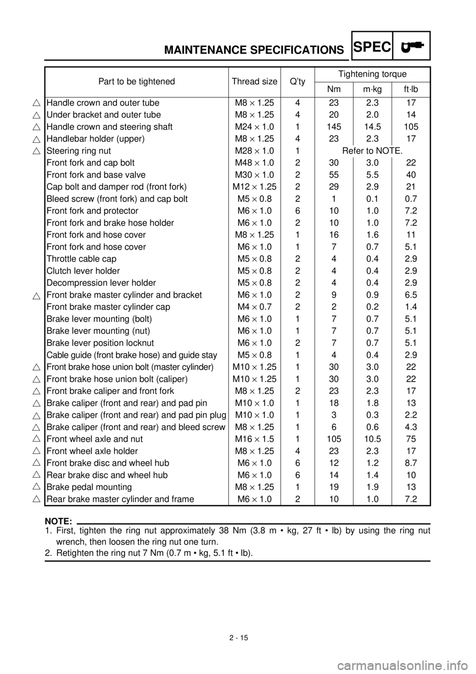
HINWEIS:NOTE:
1. First, tighten the ring nut approximately 38 Nm (3.8 m • kg, 27 ft • lb) by using the ring nut
wrench, then loosen the ring nut one turn.
2. Retighten the ring nut 7 Nm (0.7 m • kg, 5.1 ft • lb).Part to be tightened Thread size Q’tyTightening torque
Nm m·kg ft·lb
Handle crown and outer tube M8 ´ 1.25 4 23 2.3 17
Under bracket and outer tube M8 ´ 1.25 4 20 2.0 14
Handle crown and steering shaft M24 ´ 1.0 1 145 14.5 105
Handlebar holder (upper) M8 ´ 1.25 4 23 2.3 17
Steering ring nut M28 ´ 1.0 1 Refer to NOTE.
Front fork and cap bolt M48 ´ 1.0 2 30 3.0 22
Front fork and base valve M30 ´ 1.0 2 55 5.5 40
Cap bolt and damper rod (front fork) M12 ´ 1.25 2 29 2.9 21
Bleed screw (front fork) and cap bolt M5 ´ 0.8 2 1 0.1 0.7
Front fork and protector M6 ´ 1.0 6 10 1.0 7.2
Front fork and brake hose holder M6 ´ 1.0 2 10 1.0 7.2
Front fork and hose cover M8 ´ 1.25 1 16 1.6 11
Front fork and hose cover M6 ´ 1.0 1 7 0.7 5.1
Throttle cable cap M5 ´ 0.8 2 4 0.4 2.9
Clutch lever holder M5 ´ 0.8 2 4 0.4 2.9
Decompression lever holder M5 ´ 0.8 2 4 0.4 2.9
Front brake master cylinder and bracket M6 ´ 1.0 2 9 0.9 6.5
Front brake master cylinder cap M4 ´ 0.7 2 2 0.2 1.4
Brake lever mounting (bolt) M6 ´ 1.0 1 7 0.7 5.1
Brake lever mounting (nut) M6 ´ 1.0 1 7 0.7 5.1
Brake lever position locknut M6 ´ 1.0 2 7 0.7 5.1
Cable guide (front brake hose) and guide stay M5 ´ 0.8 1 4 0.4 2.9
Front brake hose union bolt (master cylinder)M10 ´ 1.25 1 30 3.0 22
Front brake hose union bolt (caliper) M10 ´ 1.25 1 30 3.0 22
Front brake caliper and front fork M8 ´ 1.25 2 23 2.3 17
Brake caliper (front and rear) and pad pin M10 ´ 1.0 1 18 1.8 13
Brake caliper (front and rear) and pad pin plug M10 ´ 1.0 1 3 0.3 2.2
Brake caliper (front and rear) and bleed screw M8 ´ 1.25 1 6 0.6 4.3
Front wheel axle and nut M16 ´ 1.5 1 105 10.5 75
Front wheel axle holder M8 ´ 1.25 4 23 2.3 17
Front brake disc and wheel hub M6 ´ 1.0 6 12 1.2 8.7
Rear brake disc and wheel hub M6 ´ 1.0 6 14 1.4 10
Brake pedal mounting M8 ´ 1.25 1 19 1.9 13
Rear brake master cylinder and frame M6 ´ 1.0 2 10 1.0 7.2
Page 87 of 654
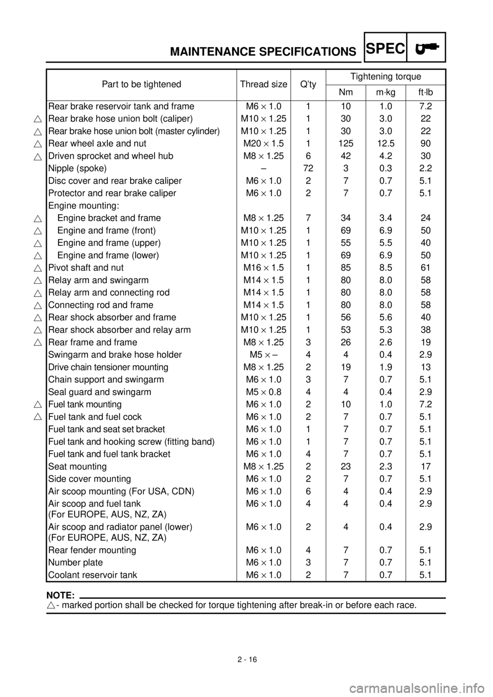
2 - 16
SPECMAINTENANCE SPECIFICATIONS
HINWEIS:NOTE:
- marked portion shall be checked for torque tightening after break-in or before each race.Part to be tightened Thread size Q’tyTightening torque
Nm m·kg ft·lb
Rear brake reservoir tank and frame M6 ´ 1.0 1 10 1.0 7.2
Rear brake hose union bolt (caliper) M10 ´ 1.25 1 30 3.0 22
Rear brake hose union bolt (master cylinder)M10 ´ 1.25 1 30 3.0 22
Rear wheel axle and nut M20 ´ 1.5 1 125 12.5 90
Driven sprocket and wheel hub M8 ´ 1.25 6 42 4.2 30
Nipple (spoke) – 72 3 0.3 2.2
Disc cover and rear brake caliper M6 ´ 1.0 2 7 0.7 5.1
Protector and rear brake caliper M6 ´ 1.0 2 7 0.7 5.1
Engine mounting:
Engine bracket and frame M8 ´ 1.25 7 34 3.4 24
Engine and frame (front) M10 ´ 1.25 1 69 6.9 50
Engine and frame (upper) M10 ´ 1.25 1 55 5.5 40
Engine and frame (lower) M10 ´ 1.25 1 69 6.9 50
Pivot shaft and nut M16 ´ 1.5 1 85 8.5 61
Relay arm and swingarm M14 ´ 1.5 1 80 8.0 58
Relay arm and connecting rod M14 ´ 1.5 1 80 8.0 58
Connecting rod and frame M14 ´ 1.5 1 80 8.0 58
Rear shock absorber and frame M10 ´ 1.25 1 56 5.6 40
Rear shock absorber and relay arm M10 ´ 1.25 1 53 5.3 38
Rear frame and frame M8 ´ 1.25 3 26 2.6 19
Swingarm and brake hose holder M5 ´ – 4 4 0.4 2.9
Drive chain tensioner mounting M8 ´ 1.25 2 19 1.9 13
Chain support and swingarm M6 ´ 1.0 3 7 0.7 5.1
Seal guard and swingarm M5 ´ 0.8 4 4 0.4 2.9
Fuel tank mounting M6 ´ 1.0 2 10 1.0 7.2
Fuel tank and fuel cock M6 ´ 1.0 2 7 0.7 5.1
Fuel tank and seat set bracket M6 ´ 1.0 1 7 0.7 5.1
Fuel tank and hooking screw (fitting band) M6 ´ 1.0 1 7 0.7 5.1
Fuel tank and fuel tank bracket M6 ´ 1.0 4 7 0.7 5.1
Seat mounting M8 ´ 1.25 2 23 2.3 17
Side cover mounting M6 ´ 1.0 2 7 0.7 5.1
Air scoop mounting (For USA, CDN) M6 ´ 1.0 6 4 0.4 2.9
Air scoop and fuel tank
(For EUROPE, AUS, NZ, ZA)M6 ´ 1.0 4 4 0.4 2.9
Air scoop and radiator panel (lower)
(For EUROPE, AUS, NZ, ZA)M6 ´ 1.0 2 4 0.4 2.9
Rear fender mounting M6 ´ 1.0 4 7 0.7 5.1
Number plate M6 ´ 1.0 3 7 0.7 5.1
Coolant reservoir tank M6 ´ 1.0 2 7 0.7 5.1
Page 88 of 654
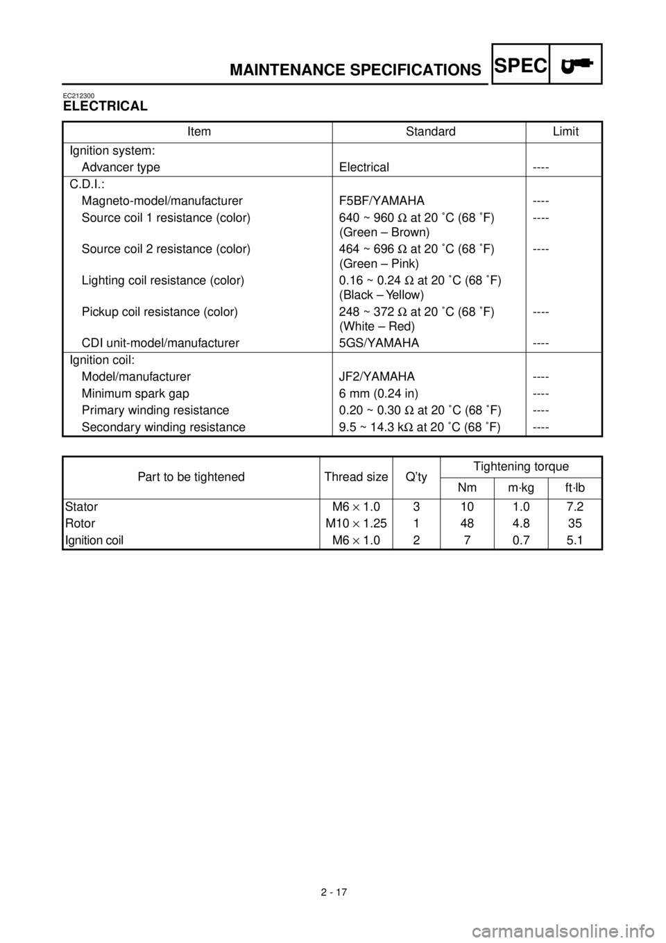
2 - 17
SPECMAINTENANCE SPECIFICATIONS
EC212300
ELECTRICAL
Item Standard Limit
Ignition system:
Advancer type Electrical ----
C.D.I.:
Magneto-model/manufacturer F5BF/YAMAHA ----
Source coil 1 resistance (color) 640 ~ 960 W at 20 ˚C (68 ˚F)
(Green – Brown)----
Source coil 2 resistance (color) 464 ~ 696 W at 20 ˚C (68 ˚F)
(Green – Pink)----
Lighting coil resistance (color) 0.16 ~ 0.24 W at 20 ˚C (68 ˚F)
(Black – Yellow)
Pickup coil resistance (color) 248 ~ 372 W at 20 ˚C (68 ˚F)
(White – Red)----
CDI unit-model/manufacturer 5GS/YAMAHA ----
Ignition coil:
Model/manufacturer JF2/YAMAHA ----
Minimum spark gap 6 mm (0.24 in) ----
Primary winding resistance 0.20 ~ 0.30 W at 20 ˚C (68 ˚F) ----
Secondary winding resistance 9.5 ~ 14.3 kW at 20 ˚C (68 ˚F) ----
Part to be tightened Thread size Q’tyTightening torque
Nm m·kg ft·lb
Stator M6 ´ 1.0 3 10 1.0 7.2
Rotor M10 ´ 1.25 1 48 4.8 35
Ignition coil M6 ´ 1.0 2 7 0.7 5.1
Page 89 of 654
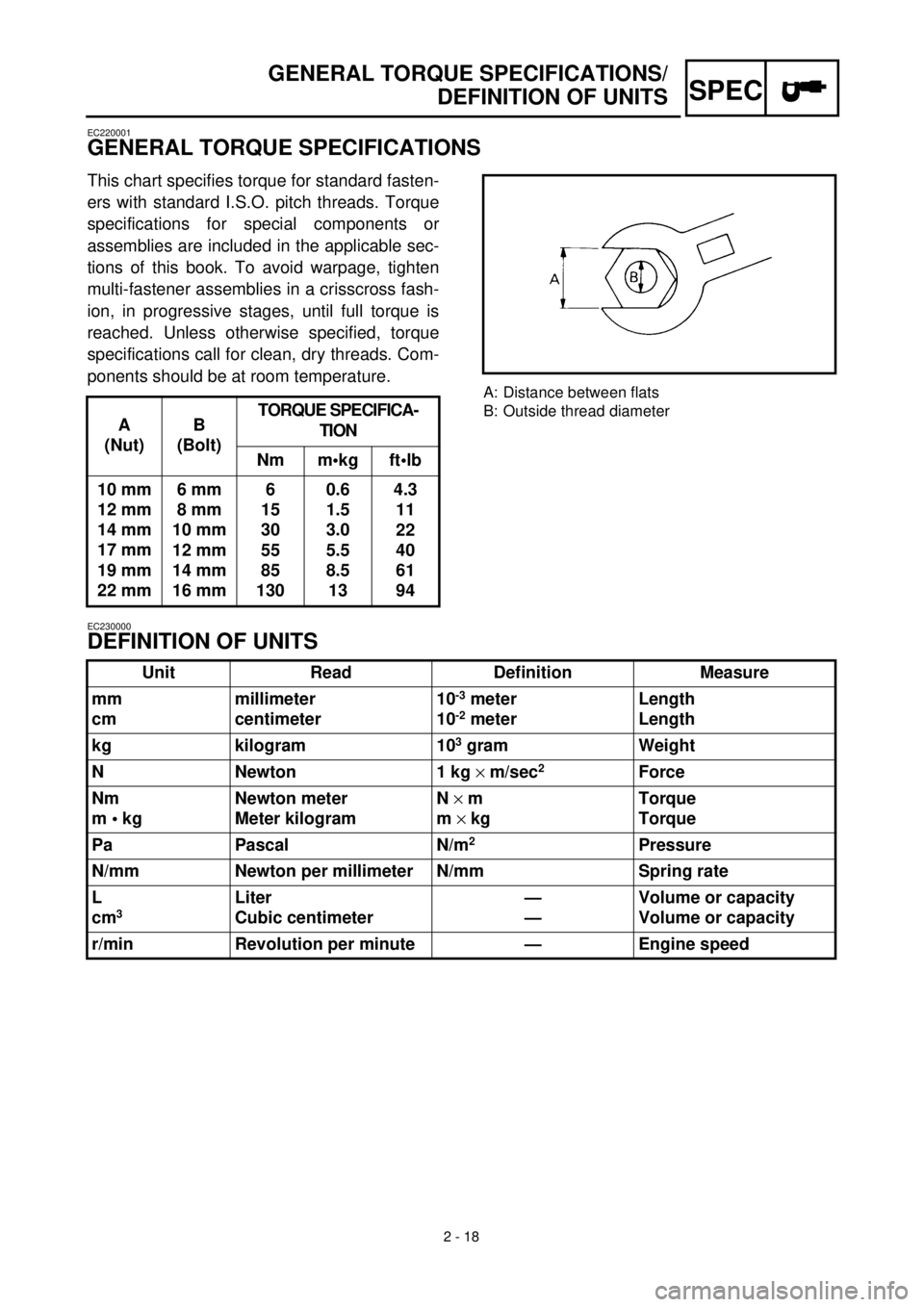
2 - 18
SPEC
GENERAL TORQUE SPECIFICATIONS/
DEFINITION OF UNITS
EC220001
GENERAL TORQUE SPECIFICATIONS
This chart specifies torque for standard fasten-
ers with standard I.S.O. pitch threads. Torque
specifications for special components or
assemblies are included in the applicable sec-
tions of this book. To avoid warpage, tighten
multi-fastener assemblies in a crisscross fash-
ion, in progressive stages, until full torque is
reached. Unless otherwise specified, torque
specifications call for clean, dry threads. Com-
ponents should be at room temperature.
A
(Nut)B
(Bolt)TORQUE SPECIFICA-
TION
Nm m•kg ft•lb
10 mm
12 mm
14 mm
17 mm
19 mm
22 mm6 mm
8 mm
10 mm
12 mm
14 mm
16 mm6
15
30
55
85
1300.6
1.5
3.0
5.5
8.5
134.3
11
22
40
61
94
A: Distance between flats
B: Outside thread diameter
EC230000
DEFINITION OF UNITS
Unit Read Definition Measure
mm
cmmillimeter
centimeter10
-3
meter
10
-2
meterLength
Length
kg kilogram 10
3
gram Weight
N Newton 1 kg
´
m/sec
2
Force
Nm
m • kgNewton meter
Meter kilogramN
´
m
m
´
kgTorque
Torque
Pa Pascal N/m
2
Pressure
N/mm Newton per millimeter N/mm Spring rate
L
cm
3
Liter
Cubic centimeter—
—Volume or capacity
Volume or capacity
r/min Revolution per minute — Engine speed
Page 90 of 654

2 - 1
CARACTERISTIQUES GENERALES
SPEC
CARACTERISTIQUES
CARACTERISTIQUES GENERALES
Nom de modèle: WR400F (EUROPE)
WR400FM (USA)
WR400F(M) (CDN, AUS, NZ, ZA)
Numéro de code de modèle: 5GS5 (USA)
5GS6 (EUROPE)
5GS8 (CDN, AUS, NZ, ZA)
Dimensions:
Longueur hors-tout 2.171 mm (85,5 in)
Largeur hors-tout 827 mm (32,6 in)
Hauteur hors-tout 1.303 mm (51,3 in)
Hauteur de la selle 998 mm (39,3 in)
Empattement 1.490 mm (58,7 in)
Garde au sol minimale 373 mm (14,7 in)
Poids en ordre de marche:
Avec plein d’huile et de carburant 122,0 kg (270 lb)
Moteur:
Type de moteur 4 temps, refroidissement liquide, double arbre à
cames en tête (DOHC)
Dispositions de cylindres Monocylindre, incliné
Cylindrée 399 cm
3
(14,1 Imp oz, 13,5 US oz)
Alésage
´
course 92,0
´
60,1 mm (3,62
´
2,37 in)
Taux de compression 12,5 : 1
Système de démarrage Démarreur au pied
Système de graissage: Carter sec
Type ou grade d’huile:
Huile de moteur
[Pour les USA et le CDN]
Huile recommandée:
Min. 5 ˚C (40 ˚F)
: Yamalube 4 (20W-40) ou SAE
20W-40 de type SH (Sans additits anti-friction)
Max. 15 ˚C (60 ˚F)
õ
: Yamalube 4 (10W-30) ou
SAE 10W-30 de type SH (Sans additits anti-friction)
ou Yamalube 4-R (15W-50) (Sans additits anti-fric-
tion)
[Excepté pour les USA et le CDN]
Qualité API “SH” ou supérieure
(Huile pour motocyclettes)
-20
-4-10
140
3010
5020
6830
8640 50
104
122¡CTemp.
¡F
10W/30
10W/40
20W/40
20W/50