YAMAHA WR 400F 2001 Owners Manual
Manufacturer: YAMAHA, Model Year: 2001, Model line: WR 400F, Model: YAMAHA WR 400F 2001Pages: 762, PDF Size: 62.36 MB
Page 671 of 762
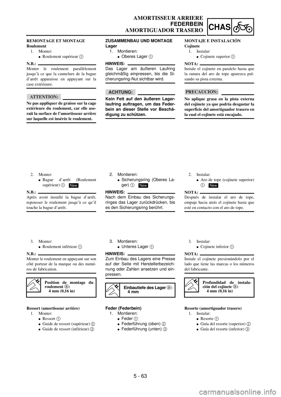
5 - 63
CHAS
AMORTISSEUR ARRIERE
FEDERBEIN
AMORTIGUADOR TRASERO
ZUSAMMENBAU UND MONTAGE
Lager
1. Montieren:
lOberes Lager 1
HINWEIS:
Das Lager am äußeren Laufring
gleichmäßig einpressen, bis die Si-
cherungsring-Nut sichtbar wird.
ACHTUNG:
Kein Fett auf den äußeren Lager-
laufring auftragen, um das Feder-
bein an dieser Stelle vor Beschä-
digung zu schützen.
2. Montieren:
lSicherungsring (Oberes La-
ger) 1
HINWEIS:
Nach dem Einbau des Sicherungs-
ringes das Lager zurückdrücken, bis
es den Sicherungsring berührt.
New
3. Montieren:
lUnteres Lager 1
HINWEIS:
Zum Einbau des Lagers eine Presse
auf der Seite mit Herstellerbezeich-
nung oder Zahlen ansetzen und ein-
pressen.
Einbautiefe des Lager a:
4 mm
Feder (Federbein)
1. Montieren:
lFeder 1
lFederführung (oben) 2
lFederführung (unten) 3 REMONTAGE ET MONTAGE
Roulement
1. Monter:
lRoulement supérieur 1
N.B.:
Monter le roulement parallèlement
jusqu’à ce que la cannelure de la bague
d’arrêt apparaisse en appuyant sur la
case extérieure.
ATTENTION:
Ne pas appliquer de graisse sur la cage
extérieure du roulement, car elle use-
rait la surface de l’amortisseur arrière
sur laquelle est insérée le roulement.
2. Monter:
lBague d’arrêt (Roulement
supérieur) 1
N.B.:
Après avoir installé la bague d’arrêt,
repousser le roulement jusqu’à ce qu’il
touche la bague d’arrêt.
New
3. Monter:
lRoulement inférieur 1
N.B.:
Monter le roulement en appuyant sur son
côté porteur de la marque ou des numé-
ros de fabrication.
Position de montage du
roulement a:
4 mm (0,16 in)
Ressort (amortisseur arrière)
1. Monter:
lRessort 1
lGuide de ressort (supérieur) 2
lGuide de ressort (inférieur) 3 MONTAJE E INSTALACIÓN
Cojinete
1. Instalar:
lCojinete superior 1
NOTA:
Instale el cojinete en paralelo hasta que
la ranura del aro de tope aparezca pul-
sando su pista externa.
PRECAUCION:
No aplique grasa en la pista externa
del cojinete ya que podría desgastar la
superficie del amortiguador trasero en
la cual el cojinete está encajado.
2. Instalar:
lAro de tope (cojinete superior)
1
NOTA:
Después de instalar el aro de tope,
empuje hacia atrás el cojinete hasta que
esté en contacto con el aro de tope.
New
3. Instalar:
lCojinete inferior 1
NOTA:
Instale el cojinete presionándolo por el
lado que tiene las marcas o los números
del fabricante.
Profundidad de instala-
ción del cojinete a:
4 mm (0,16 in)
Resorte (amortiguador trasero)
1. Instalar:
lResorte 1
lGuía del resorte (superior) 2
lGuía del resorte (inferior) 3
Page 672 of 762
5 - 64
CHASREAR SHOCK ABSORBER
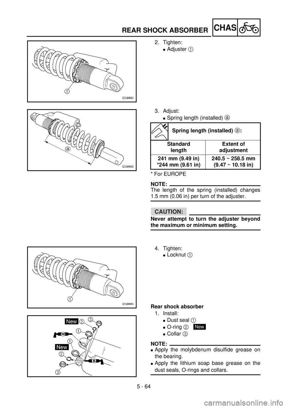
2. Tighten:
lAdjuster 1
3. Adjust:
lSpring length (installed) a
* For EUROPE
NOTE:
The length of the spring (installed) changes
1.5 mm (0.06 in) per turn of the adjuster.
CAUTION:
Never attempt to turn the adjuster beyond
the maximum or minimum setting.
Spring length (installed) a:
Standard
lengthExtent of
adjustment
241 mm (9.49 in)
*244 mm (9.61 in)240.5 ~ 258.5 mm
(9.47 ~ 10.18 in)
4. Tighten:
lLocknut 1
Rear shock absorber
1. Install:
lDust seal 1
lO-ring 2
lCollar 3
NOTE:
lApply the molybdenum disulfide grease on
the bearing.
lApply the lithium soap base grease on the
dust seals, O-rings and collars.
New
Page 673 of 762
5 - 64
CHAS
AMORTISSEUR ARRIERE
FEDERBEIN
AMORTIGUADOR TRASERO
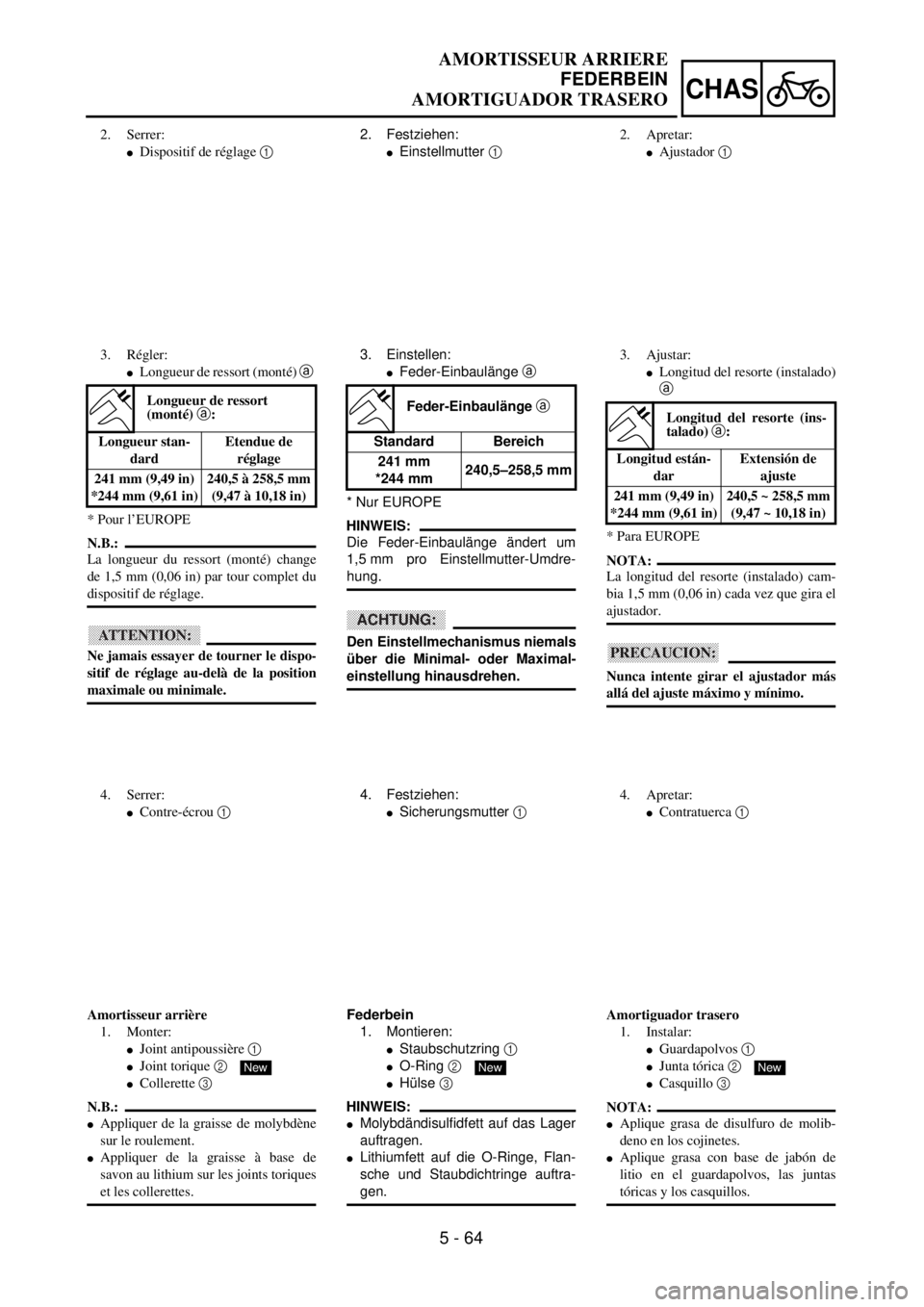
2. Festziehen:
lEinstellmutter 1
3. Einstellen:
lFeder-Einbaulänge a
* Nur EUROPE
HINWEIS:
Die Feder-Einbaulänge ändert um
1,5 mm pro Einstellmutter-Umdre-
hung.
ACHTUNG:
Den Einstellmechanismus niemals
über die Minimal- oder Maximal-
einstellung hinausdrehen.
Feder-Einbaulänge a
Standard Bereich
241 mm
*244 mm240,5–258,5 mm
4. Festziehen:
lSicherungsmutter 1
Federbein
1. Montieren:
lStaubschutzring 1
lO-Ring 2
lHülse 3
HINWEIS:
lMolybdändisulfidfett auf das Lager
auftragen.
lLithiumfett auf die O-Ringe, Flan-
sche und Staubdichtringe auftra-
gen.
New
2. Serrer:
lDispositif de réglage 1
3. Régler:
lLongueur de ressort (monté) a
* Pour l’EUROPE
N.B.:
La longueur du ressort (monté) change
de 1,5 mm (0,06 in) par tour complet du
dispositif de réglage.
ATTENTION:
Ne jamais essayer de tourner le dispo-
sitif de réglage au-delà de la position
maximale ou minimale.
Longueur de ressort
(monté) a:
Longueur stan-
dardEtendue de
réglage
241 mm (9,49 in)
*244 mm (9,61 in)240,5 à 258,5 mm
(9,47 à 10,18 in)
4. Serrer:
lContre-écrou 1
Amortisseur arrière
1. Monter:
lJoint antipoussière 1
lJoint torique 2
lCollerette 3
N.B.:
lAppliquer de la graisse de molybdène
sur le roulement.
lAppliquer de la graisse à base de
savon au lithium sur les joints toriques
et les collerettes.
New
2. Apretar:
lAjustador 1
3. Ajustar:
lLongitud del resorte (instalado)
a
* Para EUROPE
NOTA:
La longitud del resorte (instalado) cam-
bia 1,5 mm (0,06 in) cada vez que gira el
ajustador.
PRECAUCION:
Nunca intente girar el ajustador más
allá del ajuste máximo y mínimo.
Longitud del resorte (ins-
talado) a:
Longitud están-
darExtensión de
ajuste
241 mm (9,49 in)
*244 mm (9,61 in)240,5 ~ 258,5 mm
(9,47 ~ 10,18 in)
4. Apretar:
lContratuerca 1
Amortiguador trasero
1. Instalar:
lGuardapolvos 1
lJunta tórica 2
lCasquillo 3
NOTA:
lAplique grasa de disulfuro de molib-
deno en los cojinetes.
lAplique grasa con base de jabón de
litio en el guardapolvos, las juntas
tóricas y los casquillos.
New
Page 674 of 762

5 - 65
CHASREAR SHOCK ABSORBER
2. Install:
lBush 1
lCollar 2
lDust seal 3
NOTE:
lApply the molybdenum disulfide grease on
the bearing.
lApply the lithium soap base grease on the
bush, collars and dust seals.
lInstall the dust seals with their lips facing
outward.
3. Install:
lRear shock absorber
4. Install:
lBolt (rear shock absorber-frame) 1
lNut (rear shock absorber-frame) 2
NOTE:
Apply the molybdenum disulfide grease on the
bolt.
5. Install:
lPlain washer 1
lBolt (rear shock absorber-relay arm) 2
NOTE:
lApply the molybdenum disulfide grease on
the bolt.
lInsert the bolt from right side.
6. Install:
lRear frame 1
lBolt (rear frame) 2
lBolt (reservoir tank) 3
T R..56 Nm (5.6 m · kg, 40 ft · lb)
T R..53 Nm (5.3 m · kg, 38 ft · lb)
T R..29 Nm (2.9 m · kg, 21 ft · lb)
T R..10 Nm (1.0 m · kg, 7.2 ft · lb)
7. Tighten:
lScrew (air cleaner joint) 1
1
T R..3 Nm (0.3 m · kg, 2.2 ft · lb)
Page 675 of 762
5 - 65
CHAS
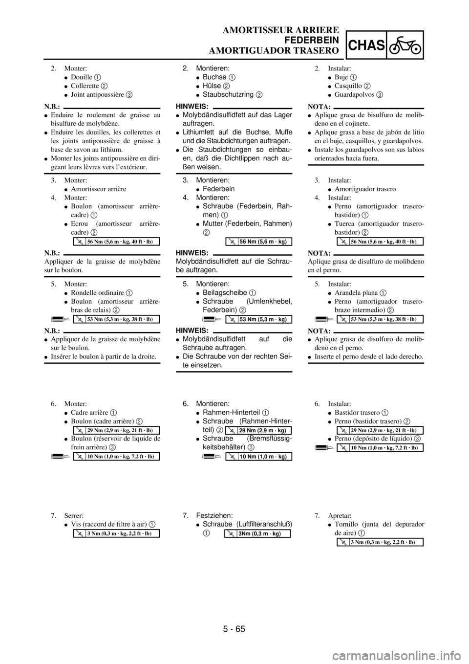
2. Montieren:
lBuchse 1
lHülse 2
lStaubschutzring 3
HINWEIS:
lMolybdändisulfidfett auf das Lager
auftragen.
lLithiumfett auf die Buchse, Muffe
und die Staubdichtungen auftragen.
lDie Staubdichtungen so einbau-
en, daß die Dichtlippen nach au-
ßen weisen.
3. Montieren:
lFederbein
4. Montieren:
lSchraube (Federbein, Rah-
men) 1
lMutter (Federbein, Rahmen)
2
HINWEIS:
Molybdändisulfidfett auf die Schrau-
be auftragen.
5. Montieren:
lBeilagscheibe 1
lSchraube (Umlenkhebel,
Federbein) 2
HINWEIS:
lMolybdändisulfidfett auf die
Schraube auftragen.
lDie Schraube von der rechten Sei-
te einsetzen.
T R..56 Nm (5,6 m · kg)
T R..53 Nm (5,3 m · kg)
6. Montieren:
lRahmen-Hinterteil 1
lSchraube (Rahmen-Hinter-
teil) 2
lSchraube (Bremsflüssig-
keitsbehälter) 3
T R..29 Nm (2,9 m · kg)
T R..10 Nm (1,0 m · kg)
7. Festziehen:
lSchraube (Luftfilteranschluß)
1
T R..3Nm (0,3 m · kg)
2. Monter:
lDouille 1
lCollerette 2
lJoint antipoussière 3
N.B.:
lEnduire le roulement de graisse au
bisulfure de molybdène.
lEnduire les douilles, les collerettes et
les joints antipoussière de graisse à
base de savon au lithium.
lMonter les joints antipoussière en diri-
geant leurs lèvres vers l’extérieur.
3. Monter:
lAmortisseur arrière
4. Monter:
lBoulon (amortisseur arrière-
cadre) 1
lEcrou (amortisseur arrière-
cadre) 2
N.B.:
Appliquer de la graisse de molybdène
sur le boulon.
5. Monter:
lRondelle ordinaire 1
lBoulon (amortisseur arrière-
bras de relais) 2
N.B.:
lAppliquer de la graisse de molybdène
sur le boulon.
lInsérer le boulon à partir de la droite.
T R..56 Nm (5,6 m · kg, 40 ft · lb)
T R..53 Nm (5,3 m · kg, 38 ft · lb)
6. Monter:
lCadre arrière 1
lBoulon (cadre arrière) 2
lBoulon (réservoir de liquide de
frein arrière) 3
T R..29 Nm (2,9 m · kg, 21 ft · lb)
T R..10 Nm (1,0 m · kg, 7,2 ft · lb)
7. Serrer:
lVis (raccord de filtre à air) 1
T R..3 Nm (0,3 m · kg, 2,2 ft · lb)
2. Instalar:
lBuje 1
lCasquillo 2
lGuardapolvos 3
NOTA:
lAplique grasa de bisulfuro de molib-
deno en el cojinete.
lAplique grasa a base de jabón de litio
en el buje, casquillos, y guardapolvos.
lInstale los guardapolvos son sus labios
orientados hacia fuera.
3. Instalar:
lAmortiguador trasero
4. Instalar:
lPerno (amortiguador trasero-
bastidor) 1
lTuerca (amortiguador trasero-
bastidor) 2
NOTA:
Aplique grasa de disulfuro de molibdeno
en el perno.
5. Instalar:
lArandela plana 1
lPerno (amortiguador trasero-
brazo intermedio) 2
NOTA:
lAplique grasa de disulfuro de molib-
deno en el perno.
lInserte el perno desde el lado derecho.
T R..56 Nm (5,6 m · kg, 40 ft · lb)
T R..53 Nm (5,3 m · kg, 38 ft · lb)
6. Instalar:
lBastidor trasero 1
lPerno (bastidor trasero) 2
lPerno (depósito de líquido) 3
T R..29 Nm (2,9 m · kg, 21 ft · lb)
T R..10 Nm (1,0 m · kg, 7,2 ft · lb)
7. Apretar:
lTornillo (junta del depurador
de aire) 1
T R..3 Nm (0,3 m · kg, 2,2 ft · lb)
AMORTISSEUR ARRIERE
FEDERBEIN
AMORTIGUADOR TRASERO
Page 676 of 762
5 - 66
CHASREAR SHOCK ABSORBER
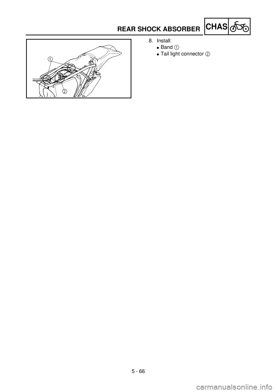
8. Install:
lBand 1
lTail light connector 2
Page 677 of 762

5 - 66
CHAS
8. Montieren:
lBand 1
lRücklicht-Steckverbinder 2 8. Monter:
lBande 1
lConnecteur de la lampe arrière
2 8. Instalar:
lBanda 1
lConector del piloto trasero 2
AMORTISSEUR ARRIERE
FEDERBEIN
AMORTIGUADOR TRASERO
Page 678 of 762

6 - 1
–+ELEC
ELECTRICAL COMPONENTS AND WIRING DIAGRAM
EC600000
ELECTRICAL
EC610000
ELECTRICAL COMPONENTS AND WIRING DIAGRAM
EC611000
ELECTRICAL COMPONENTS
1
Headlight
2
“ENGINE STOP” button
3
Regulator
4
TPS (throttle position sensor)
5
Tail light
6
CDI magneto
7
Neutral switch
8
Ignition coil
9
Spark plug
0
Lights switch
A
CDI unit
COLOR CODE
B ................... Black
Br .................. Brown
G ................... Green
Gy ................. Gray
L .................... Blue
O ................... Orange
P ................... Pink
R ................... Red
EC612000
WIRING DIAGRAM
* Except for USA
B/L
R/WL/W
LY
L
Y
B
1B L
L YBLB Y
YYLB
5LB
YBLB
LB
3
7
4 8
9
W
R Br
G P
BP
B Br
G W
R
O
L B
Y B/LL/WSb
B/L B
Y O
L
A
2
Y
Br
B/WBB/W
Gy
B
PGR
WB
L YL Y
B B/L
SbW
Sb
WL/W
R/WL/WL/WR/WSb
W
O
B
0
6
B/WGyB/WGy
O
L B
Y Sb
B/L*
B/W*
Sb*
Y
BL
B
B/W
Sb .................. Sky blue
W ................... White
Y .................... Yellow
B/L ................. Black/Blue
B/W ............... Black/White
L/W ................ Blue/White
R/W ............... Red/White
6
Page 679 of 762

–+ELEC
COMPOSANTS ELECTRIQUES ET SCHEMA DE CABLAGE
ELEKTRISCHE BAUTEILE UND SCHALTPLAN
COMPONENTES DEL SISTEMA ELÉCTRICO Y DIAGRAMA DE CABLES
ELEKTRISCHE
ANLAGE
ELEKTRISCHE BAUTEI-
LE UND SCHALTPLAN
ELEKTRISCHE BAUTEILE
1
Scheinwerfer
2
Motorstoppschalter “ENGINE
STOP”
3
Regler
4
Drosselklappensensor
5
Rücklicht
6
CDI-Schwungradmagnetzünder
7
Leerlaufschalter
8
Zündspule
9
Zündkerze
0
Lichtschalter
A
CDI-Zündbox
FARB-KODIERUNG
B ............................ schwarz
Br ........................... braun
G ............................ grün
Gy .......................... gran
L ............................. blau
O ............................ orange
P ............................ rosa
R ............................ rot
Sb .......................... hellblau
W ........................... weiß
Y ............................ gelb
B/L ......................... schwarz/blau
B/W ........................ schwarz/weiß
L/W ........................ blau/weiß
R/W ........................ rot/weiß
SCHALTPLAN
* Nicht USA
PARTIE
ELECTRIQUE
COMPOSANTS ELECTRI-
QUES ET SCHEMA DE
CABLAGE
COMPOSANTS ELECTRIQUES
1
Phare
2
Bouton d’arrêt du moteur “ENGINE
STOP”
3
Régulateur
4
TPS (détecteur de position d’accélé-
rateur)
5
Lampe arrière
6
Magnéto CDI
7
Contacteur de point mort
8
Bobine d’allumage
9
Bougie
0
Interrupteur lumières
A
Bloc CDI
CODE DE COULEUR
B............................ Noir
Br .......................... Brun
G ........................... Vert
Gy ......................... Gris
L ............................ Bleu
O ........................... Orange
P ............................ Rose
R............................ Rouge
Sb .......................... Bleu ciel
W .......................... Blanc
Y ........................... Jaune
B/L ........................ Noir/Bleu
B/W ....................... Noir/Blanc
L/W ....................... Bleu/Blanc
R/
W .................. Rouge/Blanc
SCHEMA DE CABLAGE
* Excepté pour USA
6 - 1
6
SISTEMA
ELÉCTRICO
COMPONENTES DEL SIS-
TEMA ELÉCTRICO Y
DIAGRAMA DE CABLES
COMPONENTES DEL SISTEMA
ELÉCTRICO
1
Faro
2
Botón de parada del motor “ENGINE
STOP”
3
Regulador
4
TPS (sensor de posición del acelera-
dor)
5
Luz posterior
6
Magneto CDI
7
Interruptor de punto muerto
8
Bobina de encendido
9
Bujía
0
Interruptor de las luces
A
Unidad CDI
CÓDIGO DE COLOR
B ............................... Negro
Br .............................. Marrón
G ............................... Verde
Gy ............................. Gris
L................................ Azul
O ............................... Naranja
P ................................ Rosa
R ............................... Rojo
Sb .............................. Azul cielo
W .............................. Blanco
Y ............................... Amarillo
B/L ............................ Negro/Azul
B/W........................... Negro/Blanco
L/W ........................... Azul/Blanco
R/W........................... Rojo/Blanco
DIAGRAMA DE CABLES
* Excepto para USA
Page 680 of 762
6 - 2
–+ELEC
MAP-CONTROLLED CDI UNIT
MAP-CONTROLLED CDI UNIT
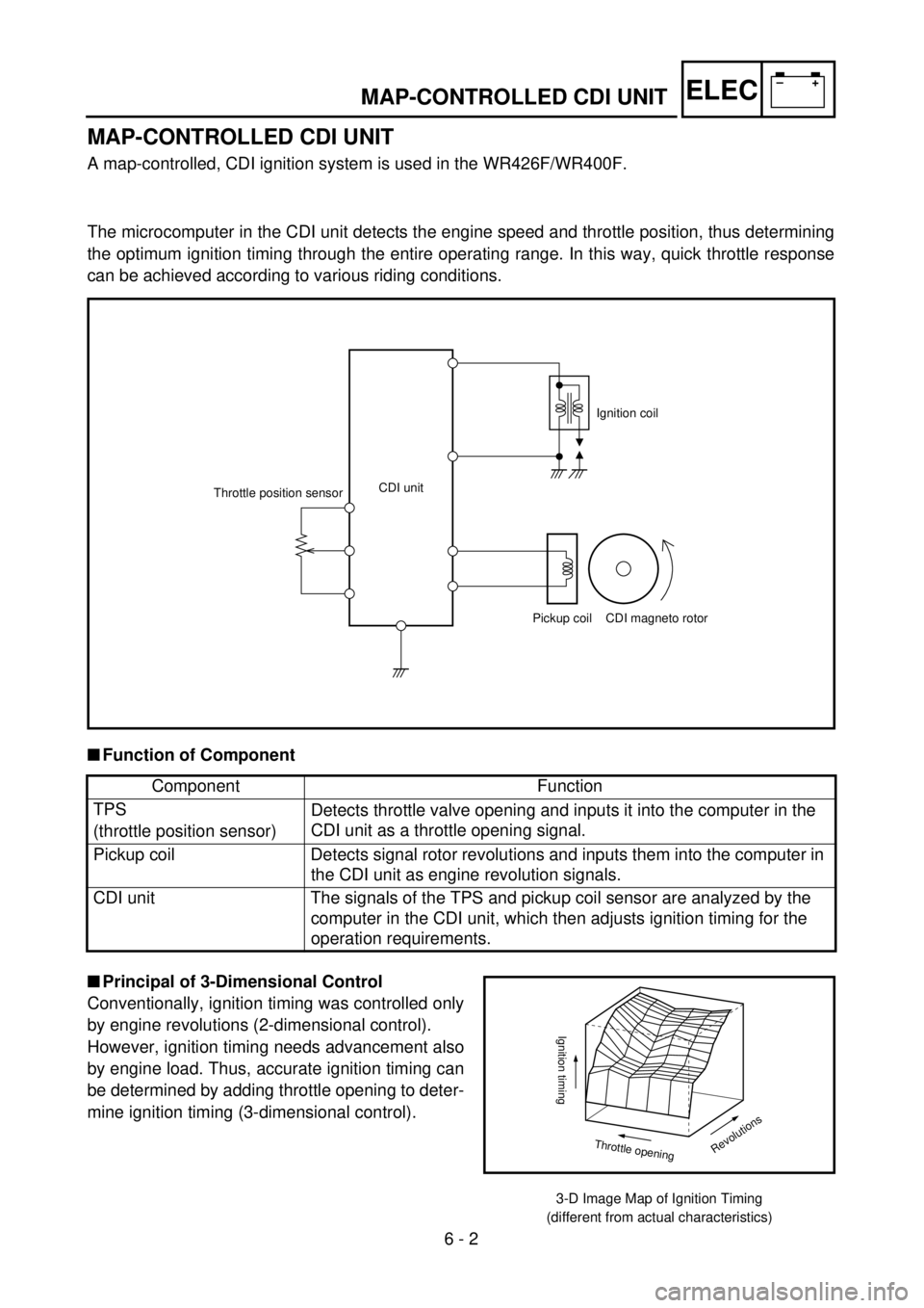
A map-controlled, CDI ignition system is used in the WR426F/WR400F.
The microcomputer in the CDI unit detects the engine speed and throttle position, thus determining
the optimum ignition timing through the entire operating range. In this way, quick throttle response
can be achieved according to various riding conditions.
CDI unit
Throttle position sensor
Pickup coil CDI magneto rotorIgnition coil
n
Function of Component
Component Function
TPS
(throttle position sensor)Detects throttle valve opening and inputs it into the computer in the
CDI unit as a throttle opening signal.
Pickup coil Detects signal rotor revolutions and inputs them into the computer in
the CDI unit as engine revolution signals.
CDI unit The signals of the TPS and pickup coil sensor are analyzed by the
computer in the CDI unit, which then adjusts ignition timing for the
operation requirements.
n
Principal of 3-Dimensional Control
Conventionally, ignition timing was controlled only
by engine revolutions (2-dimensional control).
However, ignition timing needs advancement also
by engine load. Thus, accurate ignition timing can
be determined by adding throttle opening to deter-
mine ignition timing (3-dimensional control).
3-D Image Map of Ignition Timing
(different from actual characteristics)
Revolutions
Ignition timing
Throttle opening