YAMAHA WR 450F 2007 Owners Manual
Manufacturer: YAMAHA, Model Year: 2007, Model line: WR 450F, Model: YAMAHA WR 450F 2007Pages: 794, PDF Size: 21.82 MB
Page 711 of 794
–+ELEC
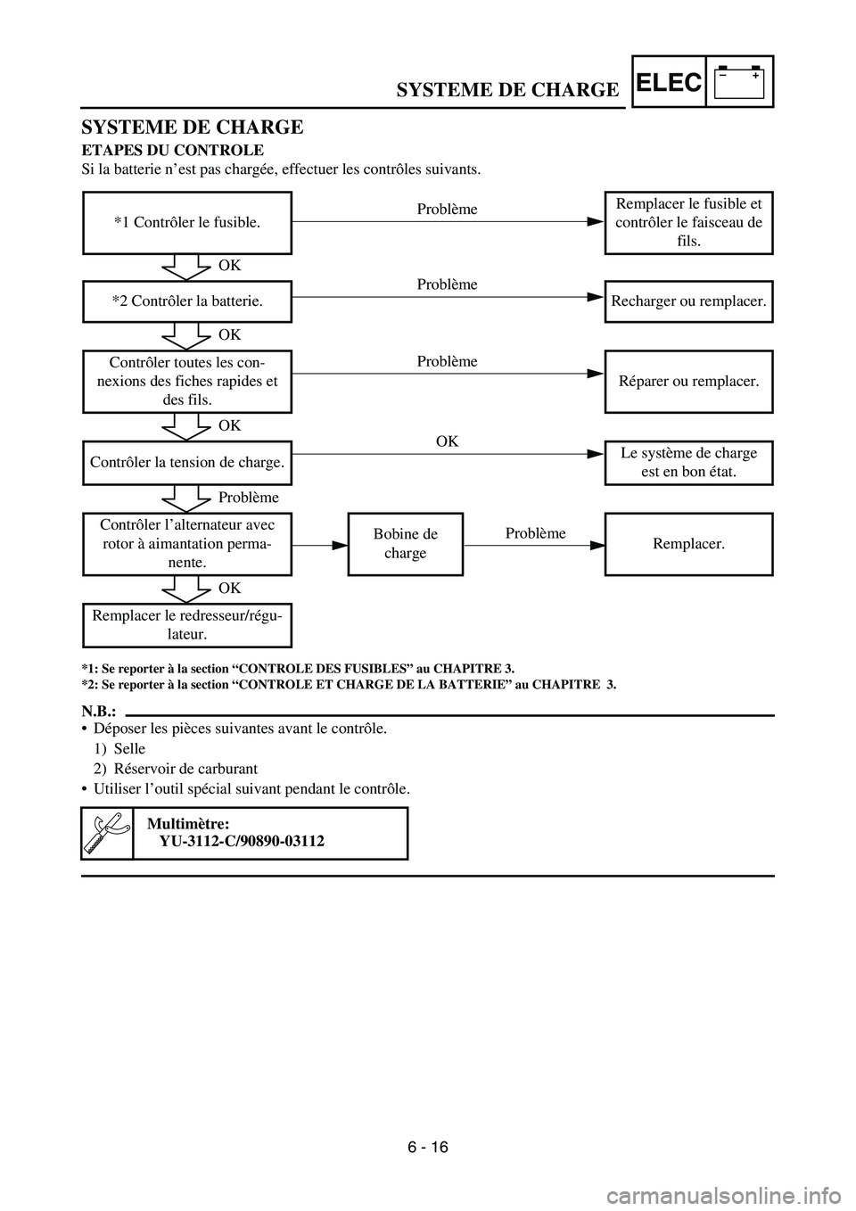
SYSTEME DE CHARGE
ETAPES DU CONTROLE
Si la batterie n’est pas chargée, effectuer les contrôles suivants.
*1: Se reporter à la section “CONTROLE DES FUSIBLES” au CHAPITRE 3.
*2: Se reporter à la section “CONTROLE ET CHARGE DE LA BATTERIE” au CHAPITRE 3.
N.B.:
Déposer les pièces suivantes avant le contrôle.
1) Selle
2) Réservoir de carburant
Utiliser l’outil spécial suivant pendant le contrôle.
Multimètre:
YU-3112-C/90890-03112
*1 Contrôler le fusible.Remplacer le fusible et
contrôler le faisceau de
fils.
*2 Contrôler la batterie. Recharger ou remplacer.
Contrôler toutes les con-
nexions des fiches rapides et
des fils.Réparer ou remplacer.
Contrôler la tension de charge.Le système de charge
est en bon état.
Contrôler l’alternateur avec
rotor à aimantation perma-
nente.Bobine de
chargeRemplacer.
Remplacer le redresseur/régu-
lateur.
OK
OK
OK
Problème
OK
Problème
Problème Problème
Problème OK
SYSTEME DE CHARGE
6 - 16
Page 712 of 794
–+ELEC
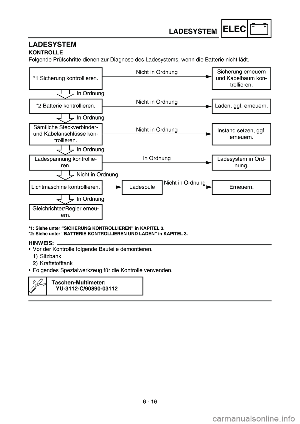
LADESYSTEM
KONTROLLE
Folgende Prüfschritte dienen zur Diagnose des Ladesystems, wenn die Batterie nicht lädt.
*1: Siehe unter “SICHERUNG KONTROLLIEREN” in KAPITEL 3.
*2: Siehe unter “BATTERIE KONTROLLIEREN UND LADEN” in KAPITEL 3.
HINWEIS:
Vor der Kontrolle folgende Bauteile demontieren.
1) Sitzbank
2) Kraftstofftank
Folgendes Spezialwerkzeug für die Kontrolle verwenden.
Taschen-Multimeter:
YU-3112-C/90890-03112
*1 Sicherung kontrollieren.Sicherung erneuern
und Kabelbaum kon-
trollieren.
*2 Batterie kontrollieren. Laden, ggf. erneuern.
Sämtliche Steckverbinder-
und Kabelanschlüsse kon-
trollieren.Instand setzen, ggf.
erneuern.
Ladespannung kontrollie-
ren.Ladesystem in Ord-
nung.
Lichtmaschine kontrollieren. Ladespule Erneuern.
Gleichrichter/Regler erneu-
ern.
In Ordnung
In Ordnung
In Ordnung
Nicht in Ordnung
In Ordnung
Nicht in Ordnung
Nicht in Ordnung Nicht in Ordnung
Nicht in Ordnung In Ordnung
LADESYSTEM
6 - 16
Page 713 of 794
–+ELEC
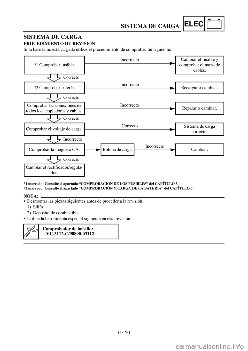
SISTEMA DE CARGA
PROCEDIMIENTO DE REVISIÓN
Si la batería no está cargada utilice el procedimiento de comprobación siguiente.
*1 marcado: Consulte el apartado “COMPROBACIÓN DE LOS FUSIBLES” del CAPÍTULO 3.
*2 marcado: Consulte el apartado “COMPROBACIÓN Y CARGA DE LA BATERÍA” del CAPÍTULO 3.
NOTA:
Desmontar las piezas siguientes antes de proceder a la revisión.
1) Sillín
2) Depósito de combustible
Utilice la herramienta especial siguiente en esta revisión.
Comprobador de bolsillo:
YU-3112-C/90890-03112
*1 Comprobar fusible.Cambiar el fusible y
comprobar el mazo de
cables.
*2 Comprobar batería. Recargar o cambiar.
Comprobar las conexiones de
todos los acopladores y cables.Reparar o cambiar.
Comprobar el voltaje de carga.Sistema de carga
correcto.
Comprobar la magneto CA. Bobina de carga Cambiar.
Cambiar el rectificador/regula-
dor.
Correcto
Correcto
Correcto
Incorrecto
Correcto
Incorrecto
Incorrecto Incorrecto
Incorrecto Correcto
SISTEMA DE CARGA
6 - 16
Page 714 of 794
6 - 17
–+ELECCHARGING SYSTEM
EC624000
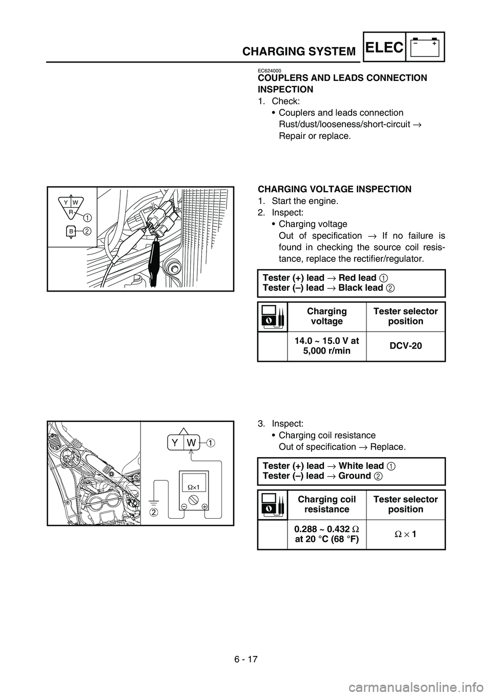
COUPLERS AND LEADS CONNECTION
INSPECTION
1. Check:
•Couplers and leads connection
Rust/dust/looseness/short-circuit →
Repair or replace.
CHARGING VOLTAGE INSPECTION
1. Start the engine.
2. Inspect:
•Charging voltage
Out of specification → If no failure is
found in checking the source coil resis-
tance, replace the rectifier/regulator.
Tester (+) lead
→ Red lead
1
Tester (–) lead
→ Black lead
2
Charging
voltageTester selector
position
14.0 ~ 15.0 V at
5,000 r/minDCV-20
R
BW Y1
2
3. Inspect:
•Charging coil resistance
Out of specification → Replace.
Tester (+) lead
→ White lead
1
Tester (–) lead
→ Ground
2
Charging coil
resistanceTester selector
position
0.288 ~ 0.432
Ω
at 20 °C (68 °F)Ω
× 1
Page 715 of 794
–+ELEC
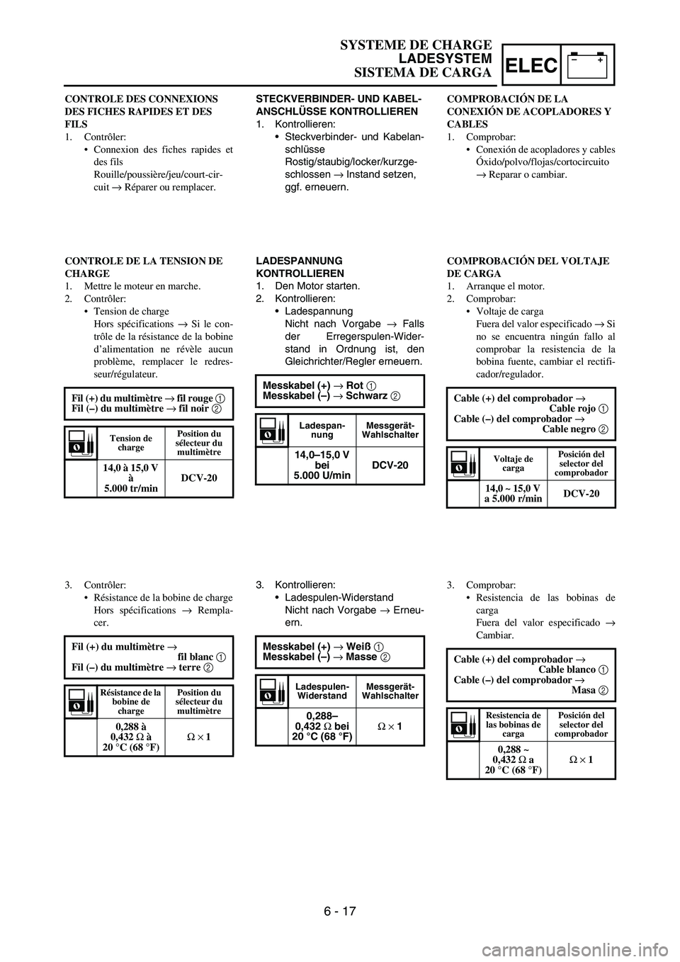
STECKVERBINDER- UND KABEL-
ANSCHLÜSSE KONTROLLIEREN
1. Kontrollieren:
Steckverbinder- und Kabelan-
schlüsse
Rostig/staubig/locker/kurzge-
schlossen → Instand setzen,
ggf. erneuern.
LADESPANNUNG
KONTROLLIEREN
1. Den Motor starten.
2. Kontrollieren:
Ladespannung
Nicht nach Vorgabe → Falls
der Erregerspulen-Wider-
stand in Ordnung ist, den
Gleichrichter/Regler erneuern.
Messkabel (+) → Rot 1
Messkabel (–) → Schwarz 2
Ladespan-
nungMessgerät-
Wahlschalter
14,0–15,0 V
bei
5.000 U/minDCV-20
3. Kontrollieren:
Ladespulen-Widerstand
Nicht nach Vorgabe → Erneu-
ern.
Messkabel (+) → Weiß 1
Messkabel (–) → Masse 2
Ladespulen-
WiderstandMessgerät-
Wahlschalter
0,288–
0,432 Ω bei
20 °C (68 °F)Ω × 1
CONTROLE DES CONNEXIONS
DES FICHES RAPIDES ET DES
FILS
1. Contrôler:
Connexion des fiches rapides et
des fils
Rouille/poussière/jeu/court-cir-
cuit → Réparer ou remplacer.
CONTROLE DE LA TENSION DE
CHARGE
1. Mettre le moteur en marche.
2. Contrôler:
Tension de charge
Hors spécifications → Si le con-
trôle de la résistance de la bobine
d’alimentation ne révèle aucun
problème, remplacer le redres-
seur/régulateur.
Fil (+) du multimètre → fil rouge 1
Fil (–) du multimètre → fil noir 2
Tension de
chargePosition du
sélecteur du
multimètre
14,0 à 15,0 V
à
5.000 tr/minDCV-20
3. Contrôler:
Résistance de la bobine de charge
Hors spécifications → Rempla-
cer.
Fil (+) du multimètre →
fil blanc 1
Fil (–) du multimètre → terre 2
Résistance de la
bobine de
chargePosition du
sélecteur du
multimètre
0,288 à
0,432 Ω à
20 °C (68 °F)Ω × 1
COMPROBACIÓN DE LA
CONEXIÓN DE ACOPLADORES Y
CABLES
1. Comprobar:
Conexión de acopladores y cables
Óxido/polvo/flojas/cortocircuito
→ Reparar o cambiar.
COMPROBACIÓN DEL VOLTAJE
DE CARGA
1. Arranque el motor.
2. Comprobar:
Voltaje de carga
Fuera del valor especificado → Si
no se encuentra ningún fallo al
comprobar la resistencia de la
bobina fuente, cambiar el rectifi-
cador/regulador.
Cable (+) del comprobador →
Cable rojo 1
Cable (–) del comprobador →
Cable negro 2
Voltaje de
cargaPosición del
selector del
comprobador
14,0 ~ 15,0 V
a 5.000 r/minDCV-20
3. Comprobar:
Resistencia de las bobinas de
carga
Fuera del valor especificado →
Cambiar.
Cable (+) del comprobador →
Cable blanco 1
Cable (–) del comprobador →
Masa 2
Resistencia de
las bobinas de
carga Posición del
selector del
comprobador
0,288 ~
0,432 Ω a
20 °C (68 °F)Ω × 1
SYSTEME DE CHARGE
LADESYSTEM
SISTEMA DE CARGA
6 - 17
Page 716 of 794

–+ELEC
6 - 18
TPS (THROTTLE POSITION SENSOR) SYSTEM
EC690000
TPS (THROTTLE POSITION SENSOR) SYSTEM
INSPECTION STEPS
If the TPS will not operate, use the following inspection steps.
NOTE:
Use the following special tools in this inspection.
Pocket tester:
YU-3112-C/90890-03112
Check entire ignition
system for connection.Repair or replace.
Check TPS. TPS coil Replace.
Check CDI unit.TPS input
voltageReplace.
OK
OK
No good
No good
No good
Page 717 of 794
–+ELEC
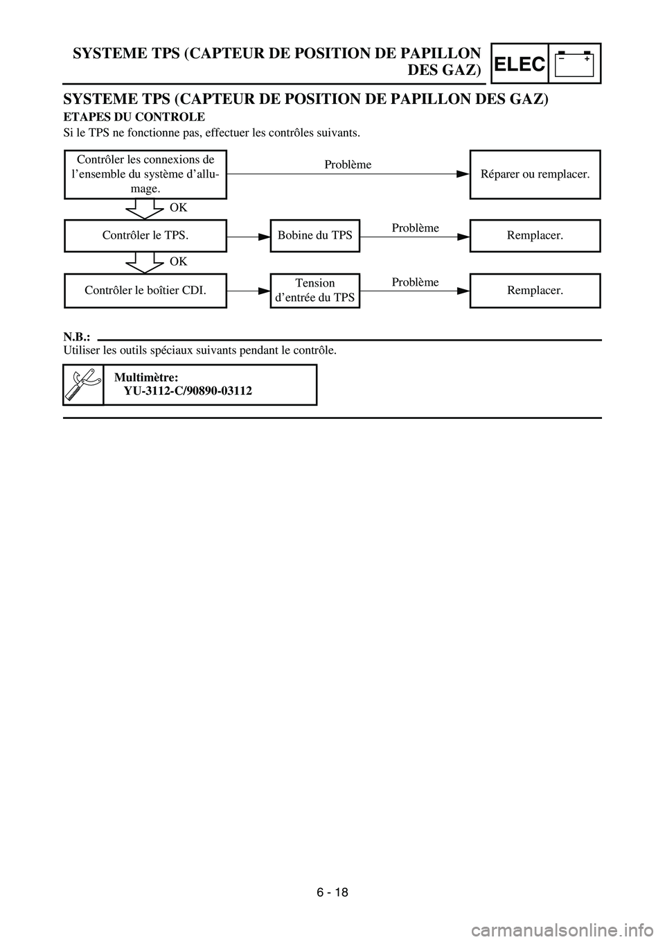
SYSTEME TPS (CAPTEUR DE POSITION DE PAPILLON DES GAZ)
ETAPES DU CONTROLE
Si le TPS ne fonctionne pas, effectuer les contrôles suivants.
N.B.:
Utiliser les outils spéciaux suivants pendant le contrôle.
Multimètre:
YU-3112-C/90890-03112
Contrôler les connexions de
l’ensemble du système d’allu-
mage.Réparer ou remplacer.
Contrôler le TPS. Bobine du TPS Remplacer.
Contrôler le boîtier CDI.Tension
d’entrée du TPSRemplacer.
OK
OK
Problème
Problème
Problème
SYSTEME TPS (CAPTEUR DE POSITION DE PAPILLON
DES GAZ)
6 - 18
Page 718 of 794

–+ELEC
DROSSELKLAPPENSENSOR
KONTROLLE
Folgende Prüfschritte dienen zur Diagnose des Drosselklappensensors, wenn dieser nicht funktio-
niert.
HINWEIS:
Folgendes Spezialwerkzeug für die Kontrolle verwenden.
Taschen-Multimeter:
YU-3112-C/90890-03112
Kabelanschlüsse des
gesamten Zündsystems
kontrollieren.Instand setzen, ggf.
erneuern.
Drosselklappensensor kon-
trollieren.Drosselklap-
pensensor-
SpuleErneuern.
Zündbox kontrollieren.Drosselklap-
pensensor-
Eingangs-
spannungErneuern.
In Ordnung
In Ordnung
Nicht in Ordnung
Nicht in Ordnung
Nicht in Ordnung
DROSSELKLAPPENSENSOR
6 - 18
Page 719 of 794

–+ELEC
SISTEMA TPS (SENSOR DE POSICIÓN DEL ACELERADOR)
PROCEDIMIENTO DE REVISIÓN
Si el TPS no funciona utilice el procedimiento de comprobación siguiente.
NOTA:
Utilice las herramientas especiales siguientes en esta revisión.
Comprobador de bolsillo:
YU-3112-C/90890-03112
Comprobar las conexiones de
todo el sistema de encendido.Reparar o cambiar.
Comprobar el TPS. Bobina del TPS Cambiar.
Comprobar la unidad CDI.Voltaje de
entrada del TPS Cambiar.
Correcto
Correcto
Incorrecto
Incorrecto
Incorrecto
SISTEMA TPS (SENSOR DE POSICIÓN DEL
ACELERADOR)
6 - 18
Page 720 of 794

6 - 19
–+ELECTPS (THROTTLE POSITION SENSOR) SYSTEM
HANDLING NOTE
CAUTION:
Do not loosen the screw {TPS (throttle
position sensor)}
1 except when changing
the TPS (throttle position sensor) due to
failure because it will cause a drop in
engine performance.
1
EC624000
COUPLERS AND LEADS CONNECTION
INSPECTION
1. Check:
•Couplers and leads connection
Rust/dust/looseness/short-circuit →
Repair or replace.
TPS COIL INSPECTION
1. Inspect:
•TPS coil resistance
Out of specification → Replace.
2. Loosen:
•Throttle stop screw 1
NOTE:
Turn out the throttle stop screw until the throt-
tle shaft is in the full close position.Tester (+) lead
→ Blue lead
1
Tester (–) lead
→ Black lead
2
TPS coil
resistanceTester selector
position
4 ~ 6 kΩ at
20 °C (68 °F)kΩ × 1