engine YAMAHA WR 450F 2008 Manual Online
[x] Cancel search | Manufacturer: YAMAHA, Model Year: 2008, Model line: WR 450F, Model: YAMAHA WR 450F 2008Pages: 224, PDF Size: 13.7 MB
Page 177 of 224

6-16
FRONT FORK
FRONT FORK
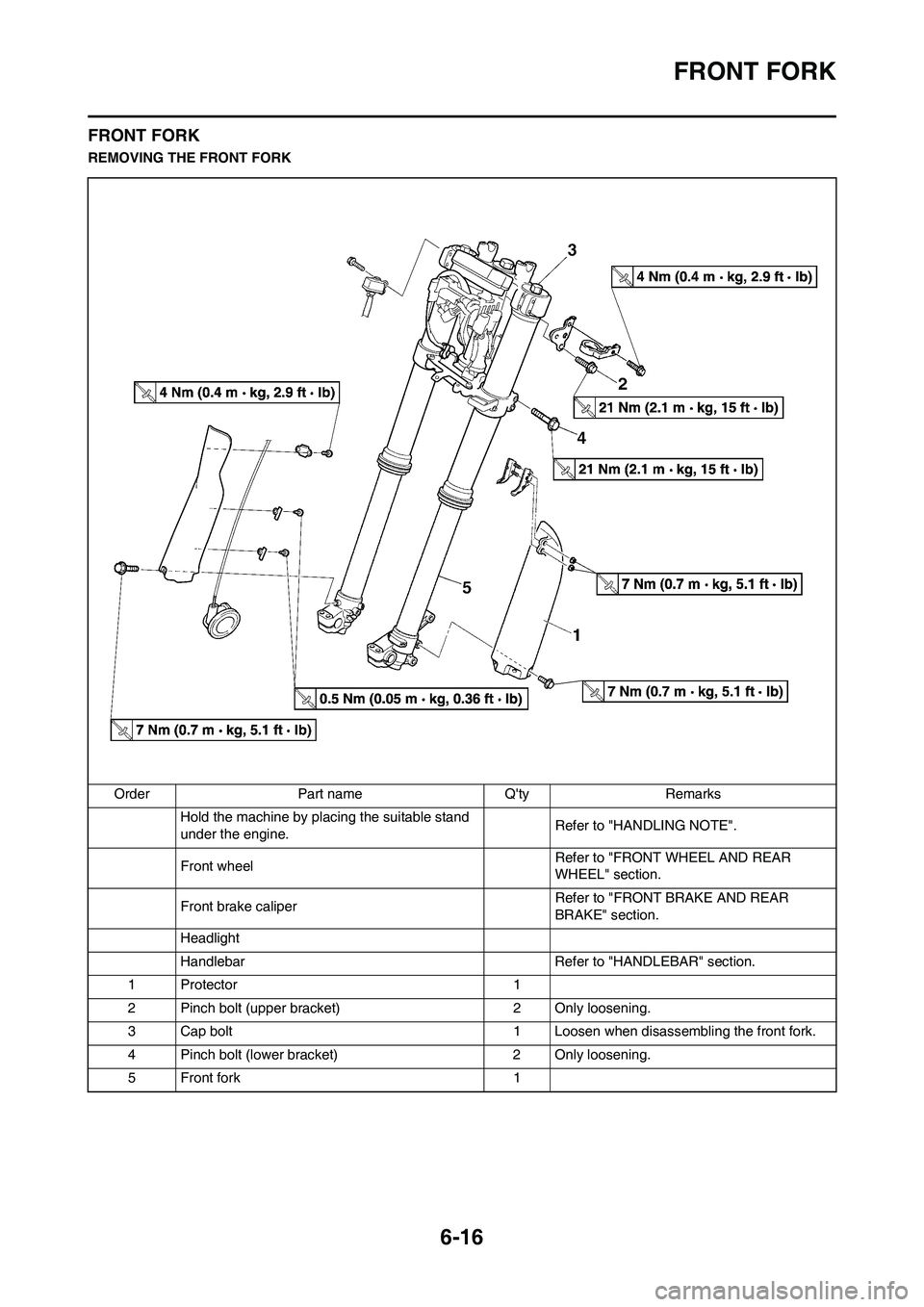
REMOVING THE FRONT FORK
Order Part name Q'ty Remarks
Hold the machine by placing the suitable stand
under the engine.Refer to "HANDLING NOTE".
Front wheel Refer to "FRONT WHEEL AND REAR
WHEEL" section.
Front brake caliper Refer to "FRONT BRAKE AND REAR
BRAKE" section.
Headlight
Handlebar Refer to "HANDLEBAR" section.
1 Protector 1
2 Pinch bolt (upper bracket) 2 Only loosening.
3 Cap bolt 1 Loosen when disassembling the front fork.
4 Pinch bolt (lower bracket) 2 Only loosening.
5 Front fork 1
Page 184 of 224

6-23
HANDLEBAR
HANDLEBAR
REMOVING THE HANDLEBAR
Order Part name Q'ty Remarks
Headlight
1 Hot starter cable 1 Disconnect at the lever side.
2 Hot starter lever holder 1
3 Clutch cable 1 Disconnect at the lever side.
4 Clutch lever holder 1 Disconnect the clutch switch lead.
5 Engine stop switch 1 Disconnect the engine stop switch lead.
6 Brake master cylinder 1 Refer to removal section.
7 Start switch 1 Disconnect the start switch lead.
8 Throttle cable cap 1
9 Throttle cable #1 (pulled) 1 Disconnect at the throttle side.
10 Throttle cable #2 (pushed) 1 Disconnect at the throttle side.
11 Right grip 1 Refer to removal section.
12 Tube guide 1
13 Left grip 1 Refer to removal section.
14 Handlebar upper holder 2
15 Handlebar 1
16 Handlebar lower holder 2
Page 186 of 224

6-25
HANDLEBAR
5. Install:
• Right grip "1"
•Collar "2"
Apply the adhesive on the tube
guide "3".
• Before applying the adhesive, wipe
off grease or oil on the tube guide
surface "a" with a lacquer thinner.
• Install the grip to the tube guide so
that the grip match mark "b" and
tube guide slot "c" form the angle as
shown.
6. Install:
• Grip cap cover "1"
• Throttle grip "2"
Apply the lithium soap base grease
on the throttle grip sliding surface.
7. Install:
• Throttle cables "1"
To tube guide "2".
Apply the lithium soap base grease
on the throttle cable end and tube
guide cable winding portion.
8. Install:
• Throttle cable cap "1"
• Screw (throttle cable cap) "2"
After tightening the screws, check
that the throttle grip "3" moves
smoothly. If it does not, retighten
the bolts for adjustment.
9. Install:
• Grip cap cover "1"
• Cover (throttle cable cap) "2"
10. Install:
• Start switch "1"
• Brake master cylinder "2"
• Brake master cylinder bracket "3"
• Bolt (brake master cylinder brack-
et) "4"
•Clamp "5"
• The start switch and brake master
cylinder bracket should be installed
according to the dimensions
shown.
• Install the bracket so that the arrow
mark "a" faces upward.
• First tighten the bolt on the upper
side of the brake master cylinder
bracket, and then tighten the bolt on
the lower side.
11. Install:
• Engine stop switch "1"
• Clutch lever holder "2"
• Bolt (clutch lever holder) "3"
• Hot starter lever holder "4"
• Bolt (hot starter lever holder) "5"
• Clamp "6"
• The engine stop switch, clutch lever
holder and clamp should be in-
stalled according to the dimensions
shown.
• Pass the engine stop switch lead in
the middle of the clutch lever hold-
er.
Screw (throttle cable
cap):
4 Nm (0.4 m•kg, 2.9
ft•lb)
Bolt (brake master cylin-
der bracket):
9 Nm (0.9 m•kg, 6.5
ft•lb)
Bolt (clutch lever holder):
4 Nm (0.4 m•kg, 2.9
ft•lb)
Bolt (hot starter lever
holder):
4 Nm (0.4 m•kg, 2.9
ft•lb)
Page 188 of 224

6-27
STEERING
STEERING
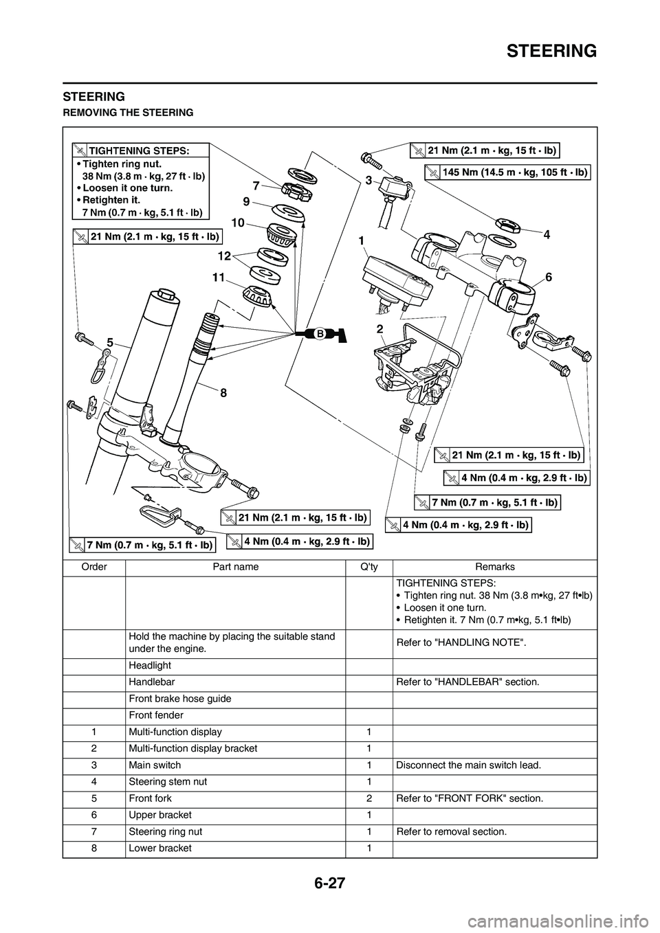
REMOVING THE STEERING
Order Part name Q'ty Remarks
TIGHTENING STEPS:
• Tighten ring nut. 38 Nm (3.8 m•kg, 27 ft•lb)
• Loosen it one turn.
• Retighten it. 7 Nm (0.7 m•kg, 5.1 ft•lb)
Hold the machine by placing the suitable stand
under the engine.Refer to "HANDLING NOTE".
Headlight
Handlebar Refer to "HANDLEBAR" section.
Front brake hose guide
Front fender
1 Multi-function display 1
2 Multi-function display bracket 1
3 Main switch 1 Disconnect the main switch lead.
4 Steering stem nut 1
5 Front fork 2 Refer to "FRONT FORK" section.
6 Upper bracket 1
7 Steering ring nut 1 Refer to removal section.
8 Lower bracket 1
Page 192 of 224

6-31
SWINGARM
SWINGARM
REMOVING THE SWINGARM
Order Part name Q'ty Remarks
Hold the machine by placing the suitable stand
under the engine.Refer to "HANDLING NOTE".
Brake hose holder Refer to "FRONT BRAKE AND REAR
BRAKE" section.
Rear brake caliperRefer to "FRONT BRAKE AND REAR
BRAKE" section.
Bolt (brake pedal) Shift the brake pedal backward.
Drive chain
1 Drive chain support 1
2 Lower chain tensioner 1
3 Bolt (rear shock absorber-relay arm) 1 Hold the swingarm.
4 Bolt (connecting rod) 1
5 Pivot shaft 1
6 Swingarm 1
Page 197 of 224

6-36
REAR SHOCK ABSORBER
REAR SHOCK ABSORBER
REMOVING THE REAR SHOCK ABSORBER
Order Part name Q'ty Remarks
Hold the machine by placing the suitable stand
under the engine.Refer to "HANDLING NOTE".
Seat and side cover Refer to "REMOVING THE SEAT, FUEL
TANK AND SIDE COVERS" section in the
CHAPTER 3.
Silencer Refer to "REMOVING THE EXHAUST PIPE
AND SILENCER" section in the CHAPTER 3.
Drain the coolant.Refer to "CHANGING THE COOLANT" sec-
tion in the CHAPTER 3.
Catch tank breather hose Disconnect at the catch tank side.
Catch tank hose Disconnect at the catch tank side.
Air induction hose (air cut-off valve-air filter case) Disconnect at the air filter case side.
Cylinder head breather hose Disconnect at the air filter case side.
BatteryRefer to "CHECKING AND CHARGING THE
BATTERY" section in the CHAPTER 3.
Disconnect the starter relay coupler.
Starter motor lead Disconnect at the starter relay side.
Page 202 of 224

7-1
ELECTRICAL COMPONENTS AND WIRING DIAGRAM
ELECTRICAL
ELECTRICAL
COMPONENTS AND
WIRING DIAGRAM
ELECTRICAL COMPONENTS
1. Headlight
2. Multi-function display
3. Engine stop switch
4. Clutch switch
5. Diode
6. Starter relay diode
7. Throttle position sensor
8. Starter relay9. Fuse
10. Starting circuit cut-off relay
11. CDI unit
12. Taillight
13. Neutral switch
14. Starter motor
15. AC magneto
16. Rectifier/regulator17. Ignition coil
18. Spark plug
19. Start switch
20. Main switch
21. Speed sensor
22. Battery
Page 203 of 224

7-2
ELECTRICAL COMPONENTS AND WIRING DIAGRAM
WIRING DIAGRAM
1. Headlight
2. Multi-function display
3. Engine stop switch
4. Clutch switch
5. Diode
6. Starter relay diode
7. Throttle position sensor
8. Starter relay
9. Fuse
10. Starting circuit cut-off relay
11. CDI unit
12. Taillight
13. Neutral switch
14. Starter motor
15. AC magneto
16. Rectifier/regulator
17. Ignition coil
18. Spark plug
19. Start switch
20. Main switch
21. Speed sensor
22. Battery
*1: For USA
*2: Except for USACOLOR CODE
BBlack
Br Brown
Ch Chocolate
Dg Dark green
GGreen
Gy Gray
LBlue
O Orange
RRed
Sb Sky blue
WWhite
YYellow
B/L Black/Blue
B/W Black/White
L/B Blue/Black
L/R Blue/Red
L/Y Blue/Yellow
L/W Blue/White
R/B Red/Black
R/W Red/White
7
Page 204 of 224

7-3
IGNITION SYSTEM
IGNITION SYSTEM
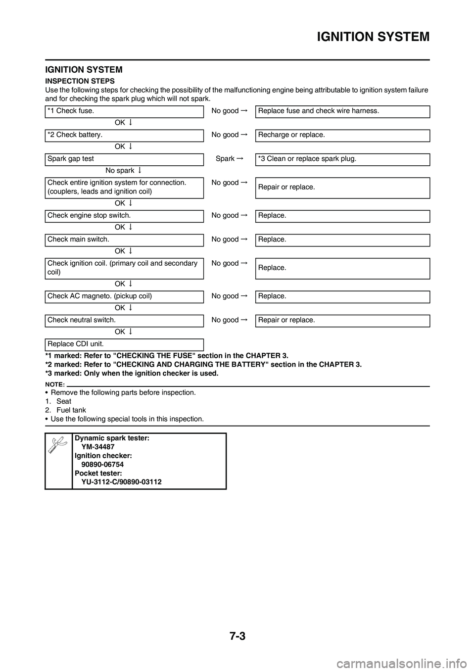
INSPECTION STEPS
Use the following steps for checking the possibility of the malfunctioning engine being attributable to ignition system failure
and for checking the spark plug which will not spark.
*1 marked: Refer to "CHECKING THE FUSE" section in the CHAPTER 3.
*2 marked: Refer to "CHECKING AND CHARGING THE BATTERY" section in the CHAPTER 3.
*3 marked: Only when the ignition checker is used.
• Remove the following parts before inspection.
1. Seat
2. Fuel tank
• Use the following special tools in this inspection.
*1 Check fuse. No good→Replace fuse and check wire harness.
OK↓
*2 Check battery. No good→Recharge or replace.
OK↓
Spark gap test Spark→*3 Clean or replace spark plug.
No spark↓
Check entire ignition system for connection.
(couplers, leads and ignition coil)No good→
Repair or replace.
OK↓
Check engine stop switch. No good→Replace.
OK↓
Check main switch. No good→Replace.
OK↓
Check ignition coil. (primary coil and secondary
coil)No good→
Replace.
OK↓
Check AC magneto. (pickup coil) No good→Replace.
OK↓
Check neutral switch. No good→Repair or replace.
OK↓
Replace CDI unit.
Dynamic spark tester:
YM-34487
Ignition checker:
90890-06754
Pocket tester:
YU-3112-C/90890-03112
Page 205 of 224

7-4
IGNITION SYSTEM
SPARK GAP TEST
1. Disconnect the ignition coil from
spark plug.
2. Remove the ignition coil cap.
3. Connect the dynamic spark tester
"1" (ignition checker "2") as
shown.
• Ignition coil "3"
• Spark plug "4"
A. For USA and CDN
B. Except for USA and CDN
4. Kick the kickstarter crank.
5. Check the ignition spark gap.
6. Start engine, and increase spark
gap until misfire occurs. (for USA
and CDN only)
CHECKING THE COUPLERS,
LEADS AND IGNITION COIL
CONNECTION
1. Check:
• Couplers and leads connection
Rust/dust/looseness/short-circuit
→Repair or replace.
• Ignition coil and spark plug as
they are fitted
Push in the ignition coil until it
closely contacts the spark plug
hole in the cylinder head cover.
CHECKING THE ENGINE STOP
SWITCH
1. Inspect:
• Engine stop switch conductionNot conductive while it is pushed→
Replace.
Conductive while it is freed→Re-
place.
Set the tester selection position to "Ω
× 1".
2. Inspect:
• Rubber part "a"
Tears/damage→ Replace.
CHECKING THE MAIN SWITCH
1. Inspect:
• Main switch conduction
Not conductive while the main switch
is moved to "ON"→Replace.
Conductive while the main switch is
moved to "OFF"→Replace.
Set the tester selection position to
"Ω×1".
2. Inspect:
• Main switch indicator light
Use 12 V battery.Indicator light does not come on→
Replace.
3. Inspect:
• Rubber part "a"
Tears/damage→Replace.
CHECKING THE IGNITION COIL
1. Remove the ignition coil cap.
2. Inspect:
• Primary coil resistance
Out of specification→Replace.
3. Inspect:
• Secondary coil resistance
Out of specification→Replace. Minimum spark gap:
6.0 mm (0.24 in)
Tester (+) lead→Black lead "1"
Tester (-) lead→Black lead "2"
Result
Conductive (while the
engine stop switch is
pushed)
Tester (+) lead→Red lead "1"
Tester (-) lead→Brown lead "2"
Result
Conductive (while the
main switch is moved
to "ON")Battery (+) lead→Red/Black lead
"1"
Battery (-) lead→Black lead "2"
Tester (+) lead→Orange lead "1"
Tester (-) lead→Black lead "2"
Primary
coil resis-
tanceTester se-
lector posi-
tion
0.08–0.10
Ω at 20 °C
(68 °F) Ω × 1
Tester (+) lead→Orange lead "1"
Tester (-) lead→Spark plug termi-
nal "2"
Secondary
coil resis-
tanceTester se-
lector posi-
tion
4.6–6.8
kΩat 20 °C
(68 °F) kΩ × 1