YAMAHA WR 450F 2013 User Guide
Manufacturer: YAMAHA, Model Year: 2013, Model line: WR 450F, Model: YAMAHA WR 450F 2013Pages: 98, PDF Size: 2.59 MB
Page 11 of 98

1-4
1
SAFETY INFORMATION
mended by Yamaha, even if sold and
installed by a Yamaha dealer.
Aftermarket Parts, Accessories,
and Modifications
While you may find aftermarket prod-
ucts similar in design and quality to
genuine Yamaha accessories, recog-
nize that some aftermarket accessories
or modifications are not suitable be-
cause of potential safety hazards to you
or others. Installing aftermarket prod-
ucts or having other modifications per-
formed to your vehicle that change any
of the vehicle’s design or operation
characteristics can put you and others
at greater risk of serious injury or death.
You are responsible for injuries related
to changes in the vehicle.
Keep the following guidelines in mind,
as well as those provided under “Load-
ing” when mounting accessories.
Never install accessories that
would impair the performance of
your motorcycle. Carefully inspect
the accessory before using it to
make sure that it does not in any
way reduce ground clearance or
cornering clearance, limit suspen-sion travel, steering travel or con-
trol operation, or obscure lights or
reflectors.
Accessories fitted to the handle-
bar or the front fork area can
create instability due to improper
weight distribution. If accesso-
ries are added to the handlebar
or front fork area, they must be
as lightweight as possible and
should be kept to a minimum.
Bulky or large accessories may seriously affect the stability of
the motorcycle. Wind may at-
tempt to lift the motorcycle, or
the motorcycle may become un-
stable in cross winds.
Certain accessories can dis- place the operator from his or
her normal riding position. This
improper position limits the free-
dom of movement of the opera-
tor and may limit control ability,
therefore, such accessories are
not recommended.
Use caution when adding electri-
cal accessories. If electrical acces-
sories exceed the capacity of the
motorcycle’s electr ical system, an electric failure could result, which
could cause a dangerous loss of
lights or engine power.
Aftermarket Tires and Rims
The tires and rims that came with your
motorcycle were designed to match the
performance capabilities and to provide
the best combination of handling, brak-
ing, and comfort. Other tires, rims, siz-
es, and combinations may not be
appropriate. Refer to page 6-18 for tire
specifications and more information on
replacing your tires.
Transporting the Motorcycle
Be sure to observe following instruc-
tions before transporting the motorcy-
cle in another vehicle.
Remove all loose items from the
motorcycle.
Point the front wheel straight
ahead on the trailer or in the truck
bed, and choke it in a rail to pre-
vent movement.
Shift the transmission in gear (for
models with a manual transmis-
sion).
Secure the motorcycle with
1DX-9-E1.book 4 ページ 2012年7月31日 火曜日 午前9時31分
Page 12 of 98

1-5
SAFETY INFORMATION
1tie-downs or suitable straps that
are attached to solid parts of the
motorcycle, such as the frame or
upper front fork triple clamp (and
not, for example, to rubber-mount-
ed handlebars or turn signals, or
parts that could break). Choose
the location for the straps carefully
so the straps will not rub against
painted surfaces during transport.
The suspension should be com-
pressed somewhat by the
tie-downs, if possible, so that the
motorcycle will not bounce exces-
sively during transport.
1DX-9-E1.book 5 ページ 2012年7月31日 火曜日 午前9時31分
Page 13 of 98
2-1
12
DESCRIPTION
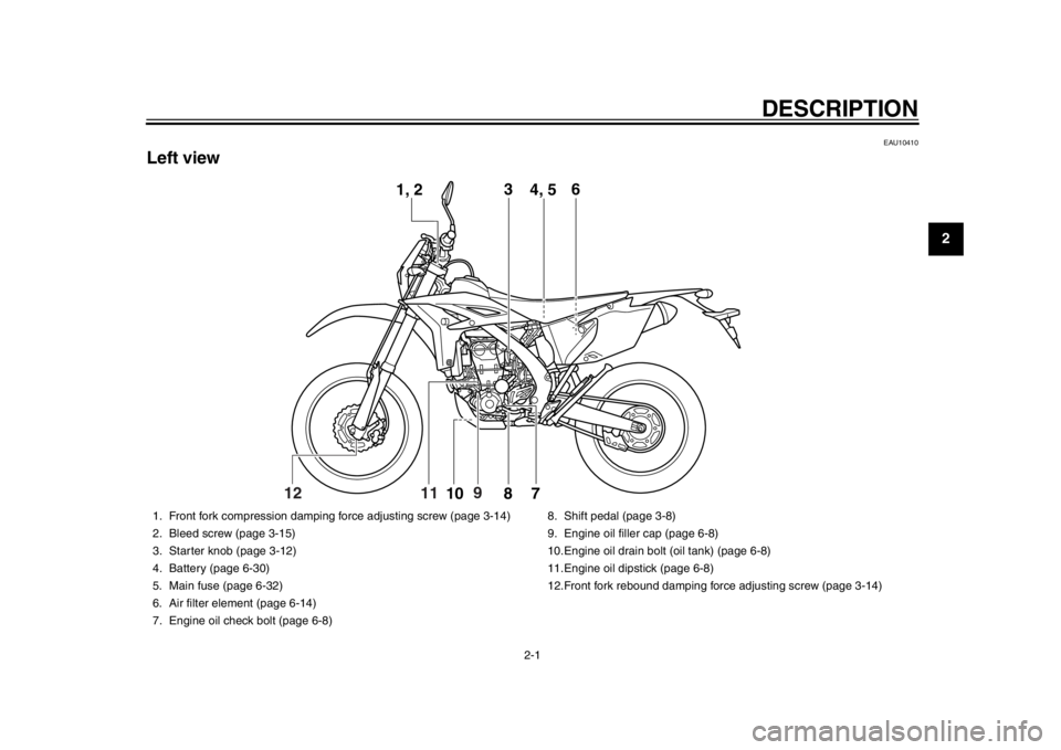
EAU10410
Left view
12
1, 23
4, 5 6
7810
9
11
1. Front fork compression damping force adjusting screw (page 3-14)
2. Bleed screw (page 3-15)
3. Starter knob (page 3-12)
4. Battery (page 6-30)
5. Main fuse (page 6-32)
6. Air filter element (page 6-14)
7. Engine oil check bolt (page 6-8) 8. Shift pedal (page 3-8)
9. Engine oil filler cap (page 6-8)
10.Engine oil drain bolt
(oil tank) (page 6-8)
11.Engine oil dipstick (page 6-8)
12.Front fork rebound damping force adjusting screw (page 3-14)
1DX-9-E1.book 1 ページ 2012年7月31日 火曜日 午前9時31分
Page 14 of 98
DESCRIPTION
2-2
12
3
4
5
6
7
8
9
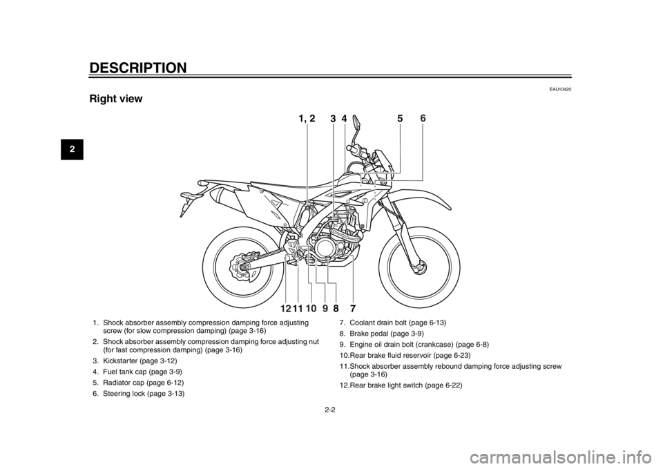
EAU10420
Right view
1, 23 5
7
8
11
6
10
12
9 4
1. Shock absorber assembly comp
ression damping force adjusting
screw (for slow compression damping) (page 3-16)
2. Shock absorber assembly compression damping force adjusting nut (for fast compression damping) (page 3-16)
3. Kickstarter (page 3-12)
4. Fuel tank cap (page 3-9)
5. Radiator cap (page 6-12)
6. Steering lock (page 3-13) 7. Coolant drain bolt (page 6-13)
8. Brake pedal (page 3-9)
9. Engine oil drain bolt (crankcase) (page 6-8)
10.Rear brake fluid reservoir (page 6-23)
11.Shock absorber assembly reboun
d damping force adjusting screw
(page 3-16)
12.Rear brake light switch (page 6-22)
1DX-9-E1.book 2 ページ 2012年7月31日 火曜日 午前9時31分
Page 15 of 98
DESCRIPTION
2-3
23
4
5
6
7
8
9
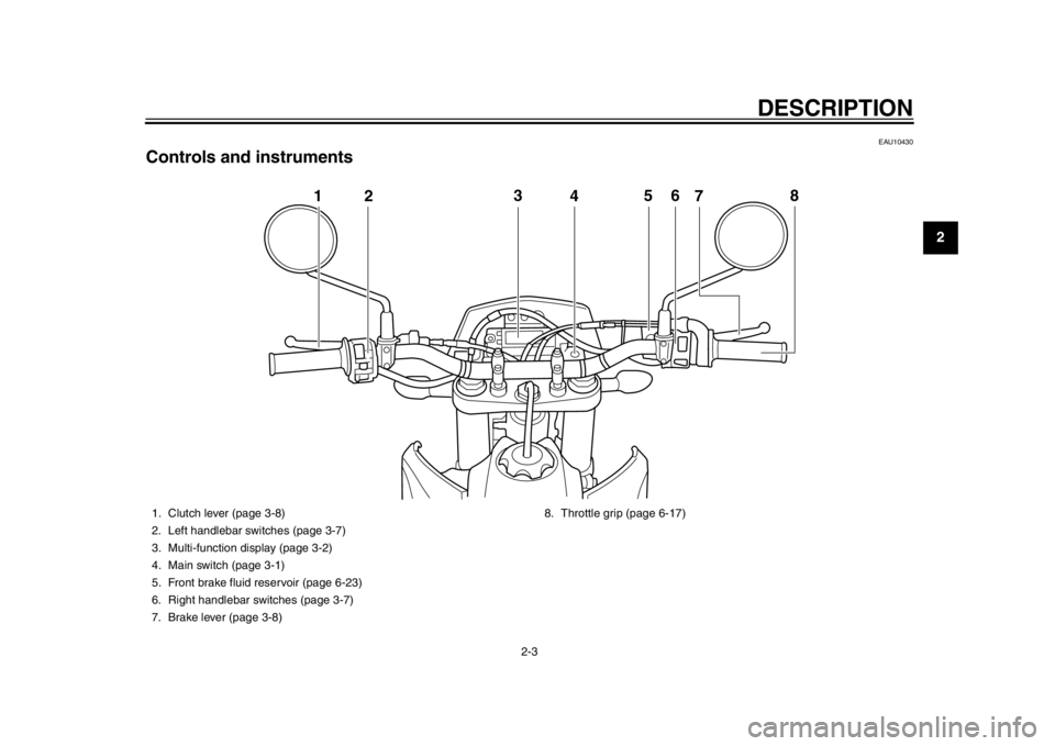
EAU10430
Controls and instruments
123
4 5
6
8
7
1. Clutch lever (page 3-8)
2. Left handlebar switches (page 3-7)
3. Multi-function display (page 3-2)
4. Main switch (page 3-1)
5. Front brake fluid reservoir (page 6-23)
6. Right handlebar switches (page 3-7)
7. Brake lever (page 3-8) 8. Throttle grip (page 6-17)
1DX-9-E1.book 3 ページ 2012年7月31日 火曜日 午前9時31分
Page 16 of 98
3-1
1
23
4
5
6
7
8
9
INSTRUMENT AND CONTROL FUNCTIONS
EAU10451
Main switch The main switch controls the ignition
and lighting systems. The various main
switch positions are described below.
EAU52430
ON
All electrical circuits are supplied with
power; the meter lighting, taillight, li-
cense plate light and auxiliary light
come on, and the engine can be start-
ed. TIPThe headlight comes on automatically
when the engine is started and stays on
until the main switch is pushed to“OFF”, even if the engine stalls.
EAU52471
OFF
All electrical systems are off.
WARNING
EWA16130
Never push the main switch to
“OFF” while the vehicle is moving,
otherwise the electrical systems will
be switched off, which may result inloss of control or an accident.NOTICE
ECA17830
Make sure that the main switch is in
“OFF” with the engine turned off,
otherwise the battery may discharge
to the point that the starter motorwill not operate properly.
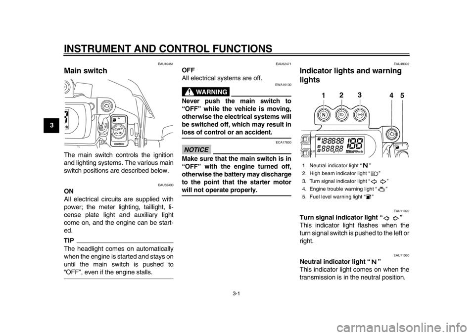
EAU49392
Indicator lights and warning
lights
EAU11020
Turn signal indicator light “ ”
This indicator light flashes when the
turn signal switch is pushed to the left or
right.
EAU11060
Neutral indicator light “ ”
This indicator light comes on when the
transmission is in the neutral position.1. Neutral indicator light “ ”
2. High beam indicator light “ ”
3. Turn signal indicator light “ ”
4. Engine trouble warning light “ ”
5. Fuel level warning light “ ”
1
2
3
4
5
1DX-9-E1.book 1 ページ 2012年7月31日 火曜日 午前9時31分
Page 17 of 98
INSTRUMENT AND CONTROL FUNCTIONS
3-2
234
5
6
7
8
9
EAU11080
High beam indicator light “ ”
This indicator light comes on when the
high beam of the headlight is switched
on.
EAU52390
Fuel level warning light “ ”
This warning light comes on when the
fuel level drops below approximately
3.0 L (0.79 US gal, 0.66 Imp.gal). When
this occurs, refuel as soon as possible.
The electrical circuit of the warning light
can be checked by pushing the main
switch to “ON”. The warning light
should come on for a few seconds, and
then go off.
If the warning light does not come on
initially when the main switch is pushed
to “ON”, or if the warning light remains
on, have a Yamaha dealer check the
electrical circuit.
EAU52400
Engine trouble warning light “ ”
This warning light comes on or flashes
if a problem is detected in the electrical
circuit monitoring the engine. If this oc-
curs, have a Yamaha dealer check the
vehicle. The electrical circuit of the warning light
can be checked by pushing the main
switch to “ON”. The warning light
should come on for a few seconds, and
then go off.
If the warning light does not come on
initially when the main switch is pushed
to “ON”, or if the warning light remains
on, have a Yamaha dealer check the
electrical circuit.
EAU52922
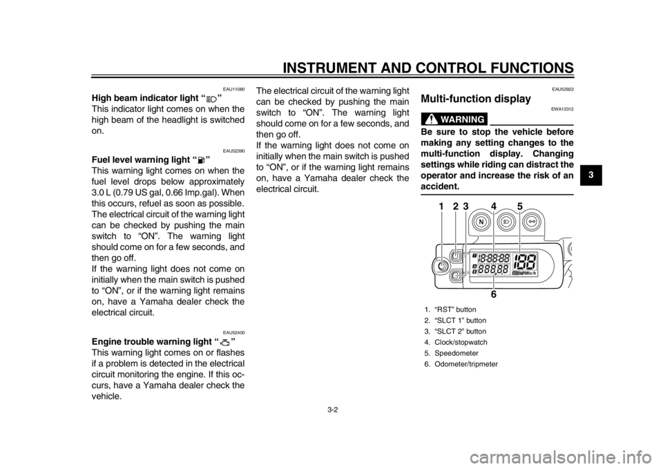
Multi-function display
WARNING
EWA12312
Be sure to stop the vehicle before
making any setting changes to the
multi-function display. Changing
settings while riding can distract the
operator and increase the risk of anaccident.1. “RST” button
2. “SLCT 1” button
3. “SLCT 2” button
4. Clock/stopwatch
5. Speedometer
6. Odometer/tripmeter
123
4
6
5
1DX-9-E1.book 2 ページ 2012年7月31日 火曜日 午前9時31分
Page 18 of 98

INSTRUMENT AND CONTROL FUNCTIONS
3-3
1
23
4
5
6
7
8
9
TIP
The multi-function display can be
set to the basic mode or the mea-
surement mode.
Tripmeter A will automatically re-
set to zero when changing from
the basic mode to the measure-ment mode or vice versa.
Basic mode:
a speedometer
an odometer
two tripmeters (which show the
distance traveled since they were last set to zero)
a clock
Measurement mode:
a speedometer
a distance-compensation tripme-
ter (which shows the accumulated
distance traveled since set to zero
and which can be calibrated to pro-
vide a more accurate tripmeter
reading)
a stopwatch (which shows the time
that has been accumulated since
the start of stopwatch measure-
ment)
TIP
Be sure to push the main switch to
“ON” before using the “SLCT 1”,
“SLCT 2” and “RST” buttons.
When the main switch is pushed to
“ON”, all of the display segments
of the multi-function display will ap-
pear and then disappear, in order
to test the electrical circuit.
For the U.K. only: To switch the
speedometer and odometer/trip-
meter displays between kilometers
and miles, press the “SLCT 2” but- ton until the display changes after
the main switch is pushed to “ON”.
Basic mode
Odometer and tripmeter modes
Push the “SLCT 2” button to switch the
display between the odometer mode
and the tripmeter modes A and B in the
following order:
odometer tripmeter A tripmeter B
odometer
1. Stopwatch indicator “ ”
2. Tripmeter A indicator “ ”/Distance-com-
pensation tripmeter “ ”
3. Tripmeter B indicator “ ”
12
3
1. Tripmeter A indicator “ ”
1
1DX-9-E1.book 3 ページ 2012年7月31日 火曜日 午前9時31分
Page 19 of 98
INSTRUMENT AND CONTROL FUNCTIONS
3-4
234
5
6
7
8
9
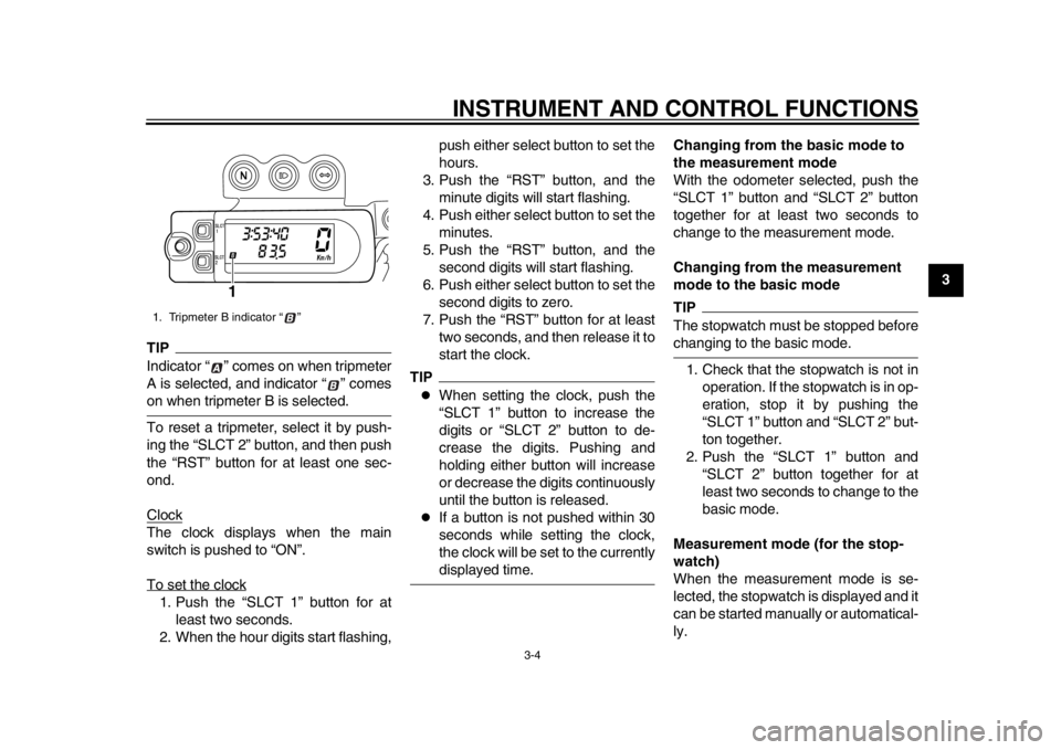
TIPIndicator “ ” comes on when tripmeter
A is selected, and indicator “ ” comeson when tripmeter B is selected.
To reset a tripmeter, select it by push-
ing the “SLCT 2” button, and then push
the “RST” button for at least one sec-
ond.
ClockThe clock displays when the main
switch is pushed to “ON”.
To set the clock1. Push the “SLCT 1” button for atleast two seconds.
2. When the hour digits start flashing, push either select button to set the
hours.
3. Push the “RST” button, and the minute digits will start flashing.
4. Push either select button to set the minutes.
5. Push the “RST” button, and the second digits will start flashing.
6. Push either select button to set the second digits to zero.
7. Push the “RST” button for at least two seconds, and then release it to
start the clock.
TIP
When setting the clock, push the
“SLCT 1” button to increase the
digits or “SLCT 2” button to de-
crease the digits. Pushing and
holding either button will increase
or decrease the digits continuously
until the button is released.
If a button is not pushed within 30
seconds while setting the clock,
the clock will be set to the currentlydisplayed time. Changing from the basic mode to
the measurement mode
With the odometer selected, push the
“SLCT 1” button and “SLCT 2” button
together for at least two seconds to
change to the measurement mode.
Changing from the measurement
mode to the basic mode
TIPThe stopwatch must be stopped beforechanging to the basic mode.
1. Check that the stopwatch is not in operation. If the stopwatch is in op-
eration, stop it by pushing the
“SLCT 1” button and “SLCT 2” but-
ton together.
2. Push the “SLCT 1” button and “SLCT 2” button together for at
least two seconds to change to the
basic mode.
Measurement mode (for the stop-
watch)
When the measurement mode is se-
lected, the stopwatch is displayed and it
can be started manually or automatical-
ly.
1. Tripmeter B indicator “ ”
1
1DX-9-E1.book 4 ページ 2012年7月31日 火曜日 午前9時31分
Page 20 of 98

INSTRUMENT AND CONTROL FUNCTIONS
3-5
1
23
4
5
6
7
8
9
TIPStarting measurement consists of the
following two starts, either of which can
be selected.
Manual start
Starting measurement by the rider
himself operating the button. (A
long push on the “SLCT 2” button
will put measurement on standby.)
Auto start
Starting timer measurement auto-
matically on detection of the move-
ment of the machine. (A long push
on the “SLCT 1” button will putmeasurement on standby.)
Manual start
The manual start is the default setting
for the stopwatch. The stopwatch indi-
cator “ ” and the distance-compensa-
tion tripmeter indicator “ ” will start
flashing. 1. Push the “RST” button to start the
stopwatch.
2. Push the “SLCT 1” button and “SLCT 2” button together to stop
the stopwatch.
3. To resume stopwatch counting, push the “SLCT 1” button and
“SLCT 2” button together.
To reset the stopwatch to zero,
push the “RST” button for at least
two seconds.
TIPThe stopwatch will continue counting
when the vehicle is stopped. To stop
and/or resume counting, repeat steps 2and 3. Auto start
1. Push the “SLCT 1” button for at
least two seconds to set the auto
start.TIPWhen the stopwatch is set to auto start,
the stopwatch indicator “ ” and the
distance-compensation tripmeter indi-
cator “ ” will start flashing, and the dig-
its in the display will start scrolling fromleft to right.
2. When the vehicle starts moving, the stopwatch will start counting.
3. Push the “SLCT 1” button and “SLCT 2” button together to stop
the stopwatch.
4. To resume counting, push the “SLCT 1” button and “SLCT 2” but-
1DX-9-E1.book 5 ページ 2012年7月31日 火曜日 午前9時31分