YAMAHA WR 450F 2013 Workshop Manual
Manufacturer: YAMAHA, Model Year: 2013, Model line: WR 450F, Model: YAMAHA WR 450F 2013Pages: 98, PDF Size: 2.59 MB
Page 51 of 98
PERIODIC MAINTENANCE AND ADJUSTMENT
6-8
2
3
4
567
8
9
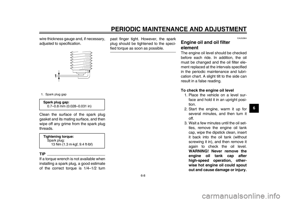
wire thickness gauge and, if necessary,
adjusted to specification.
Clean the surface of the spark plug
gasket and its mating surface, and then
wipe off any grime from the spark plug
threads.
TIPIf a torque wrench is not available when
installing a spark plug, a good estimate
of the correct torque is 1/4–1/2 turn past finger tight. However, the spark
plug should be tightened to the speci-
fied torque as soon as possible.
EAU52964
Engine oil and oil filter
element The engine oil level should be checked
before each ride. In addition, the oil
must be changed and the oil filter ele-
ment replaced at the intervals specified
in the periodic maintenance and lubri-
cation chart. A slight tilt to the side can
result in a false reading.
To check the engine oil level
1. Place the vehicle on a level sur- face and hold it in an upright posi-
tion.
2. Start the engine, warm it up for several minutes, and then turn it
off.
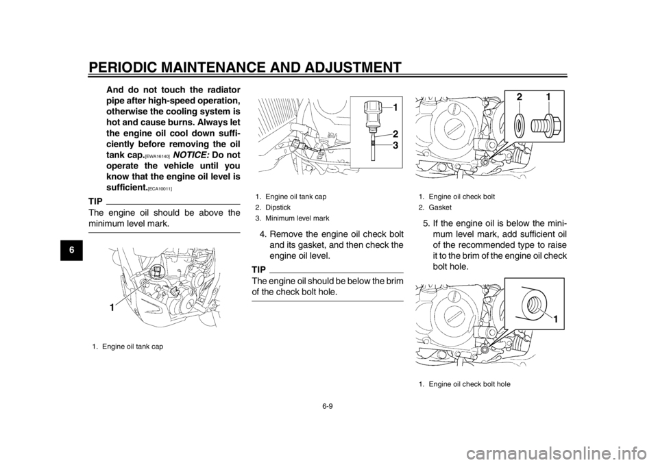
3. Wait a few minutes until the oil set- tles, remove the engine oil tank
cap, wipe the dipstick clean, insert
it back into the oil tank (without
screwing it in), and then remove it
again to check the oil level.
WARNING! Never remove the
engine oil tank cap after
high-speed operation, other-
wise hot engine oil could spout
out and cause damage or injury.
1. Spark plug gapSpark plug gap:0.7–0.8 mm (0.028–0.031 in)
Tightening torque: Spark plug: 13 Nm (1.3 m·kgf, 9.4 ft·lbf)
1DX-9-E1.book 8 ページ 2012年7月31日 火曜日 午前9時31分
Page 52 of 98
PERIODIC MAINTENANCE AND ADJUSTMENT
6-9
1
2
3
4
56
7
8
9And do not touch the radiator
pipe after high-speed operation,
otherwise the cooling system is
hot and cause burns. Always let
the engine oil cool down suffi-
ciently before removing the oil
tank cap.
[EWA16140]
NOTICE: Do not
operate the vehicle until you
know that the engine oil level is
sufficient.
[ECA10011]
TIPThe engine oil should be above theminimum level mark. 4. Remove the engine oil check bolt
and its gasket, and then check the
engine oil level.
TIPThe engine oil should be below the brimof the check bolt hole. 5. If the engine oil is below the mini-
mum level mark, add sufficient oil
of the recommended type to raise
it to the brim of the engine oil check
bolt hole.
1. Engine oil tank cap
1
1. Engine oil tank cap
2. Dipstick
3. Minimum level mark
312
1. Engine oil check bolt
2. Gasket
1. Engine oil check bolt hole
21
1
1DX-9-E1.book 9 ページ 2012年7月31日 火曜日 午前9時31分
Page 53 of 98
PERIODIC MAINTENANCE AND ADJUSTMENT
6-10
2
3
4
567
8
9
6. Install the engine oil tank cap, and
then the check bolt and its gasket.
To change the engine oil (with or
without oil filter element replace-
ment) 1. Place the vehicle on a level sur- face.
2. Start the engine, warm it up for several minutes, and then turn it
off.
3. Place an oil pan under the engine to collect the used oil.
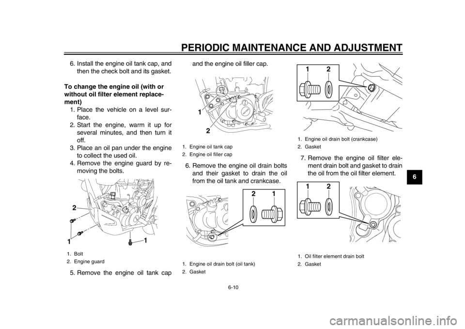
4. Remove the engine guard by re- moving the bolts.
5. Remove the engine oil tank cap and the engine oil filler cap.
6. Remove the engine oil drain bolts and their gasket to drain the oil
from the oil tank and crankcase. 7. Remove the engine oil filter ele-
ment drain bolt and gasket to drain
the oil from the oil filter element.
1. Bolt
2. Engine guard2
1
1
1. Engine oil tank cap
2. Engine oil filler cap
1. Engine oil drain bolt (oil tank)
2. Gasket
1
2
21
1. Engine oil drain bolt (crankcase)
2. Gasket
1. Oil filter element drain bolt
2. Gasket
2121
1DX-9-E1.book 10 ページ 2012年7月31日 火曜日 午前9時31分
Page 54 of 98
PERIODIC MAINTENANCE AND ADJUSTMENT
6-11
1
2
3
4
56
7
8
9
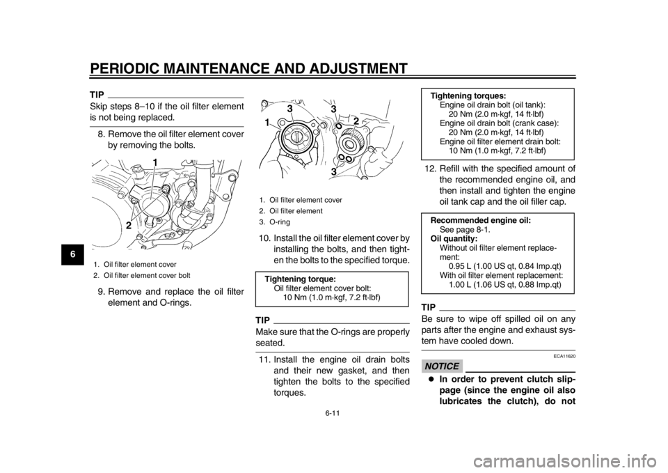
TIPSkip steps 8–10 if the oil filter elementis not being replaced.8. Remove the oil filter element cover by removing the bolts.
9. Remove and replace the oil filter element and O-rings. 10. Install the oil filter element cover by
installing the bolts, and then tight-
en the bolts to the specified torque.
TIPMake sure that the O-rings are properlyseated.
11. Install the engine oil drain bolts and their new gasket, and then
tighten the bolts to the specified
torques. 12. Refill with the specified amount of
the recommended engine oil, and
then install and tighten the engine
oil tank cap and the oil filler cap.
TIPBe sure to wipe off spilled oil on any
parts after the engine and exhaust sys-tem have cooled down.NOTICE
ECA11620
In order to prevent clutch slip-
page (since the engine oil also
lubricates the clutch), do not
1. Oil filter element cover
2. Oil filter element cover bolt
1
2
1. Oil filter element cover
2. Oil filter element
3. O-ringTightening torque:Oil filter element cover bolt:
10 Nm (1.0 m·kgf, 7.2 ft·lbf)1 2
3
3
3
Tightening torques: Engine oil drain bolt (oil tank):20 Nm (2.0 m·kgf, 14 ft·lbf)
Engine oil drain bolt (crank case):
20 Nm (2.0 m·kgf, 14 ft·lbf)
Engine oil filter element drain bolt: 10 Nm (1.0 m·kgf, 7.2 ft·lbf)
Recommended engine oil: See page 8-1.
Oil quantity:
Without oil filter element replace-
ment:0.95 L (1.00 US qt, 0.84 Imp.qt)
With oil filter element replacement: 1.00 L (1.06 US qt, 0.88 Imp.qt)
1DX-9-E1.book 11 ページ 2012年7月31日 火曜日 午前9時31分
Page 55 of 98
PERIODIC MAINTENANCE AND ADJUSTMENT
6-12
2
3
4
567
8
9
mix any chemical additives. Do
not use oils with a diesel speci-
fication of “CD” or oils of a high-
er quality than specified. In
addition, do not use oils labeled
“ENERGY CONSERVING II” or
higher.
Make sure that no foreign mate-rial enters the crankcase.
13. Start the engine, and then let it idle for several minutes while checking
it for oil leakage. If oil is leaking, im-
mediately turn the engine off and
check for the cause.
14. Turn the engine off, wait a few min- utes until the oil settles, and then
check the oil level and correct it if
necessary.
15. Install the engine guard by install- ing the bolts.
NOTICE
ECA11231
After changing the engine oil, make
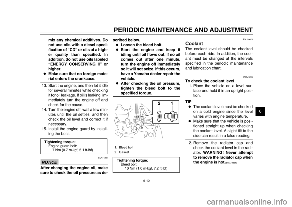
sure to check the oil pressure as de- scribed below.
Loosen the bleed bolt.
Start the engine and keep it
idling until oil flows out. If no oil
comes out after one minute,
turn the engine off immediately
so it will not seize. If this occurs,
have a Yamaha dealer repair the
vehicle.
After checking the oil pressure,
tighten the bleed bolt to thespecified torque.
EAU20070
Coolant The coolant level should be checked
before each ride. In addition, the cool-
ant must be changed at the intervals
specified in the periodic maintenance
and lubrication chart.
EAUM1295
To check the coolant level
1. Place the vehicle on a level sur- face and hold it in an upright posi-
tion.TIP
The coolant level must be checked
on a cold engine since the level
varies with engine temperature.
Make sure that the vehicle is posi-
tioned straight up when checking
the coolant level. A slight tilt to theside can result in a false reading.
2. Remove the radiator cap and check the coolant level in the radi-
ator. WARNING! Never attempt
to remove the radiator cap when
the engine is hot.
[EWA10381]
Tightening torque: Engine guard bolt:
7 Nm (0.7 m·kgf, 5.1 ft·lbf)
1. Bleed bolt
2. GasketTightening torque:Bleed bolt:10 Nm (1.0 m·kgf, 7.2 ft·lbf)
21
1DX-9-E1.book 12 ページ 2012年7月31日 火曜日 午前9時31分
Page 56 of 98
PERIODIC MAINTENANCE AND ADJUSTMENT
6-13
1
2
3
4
56
7
8
9
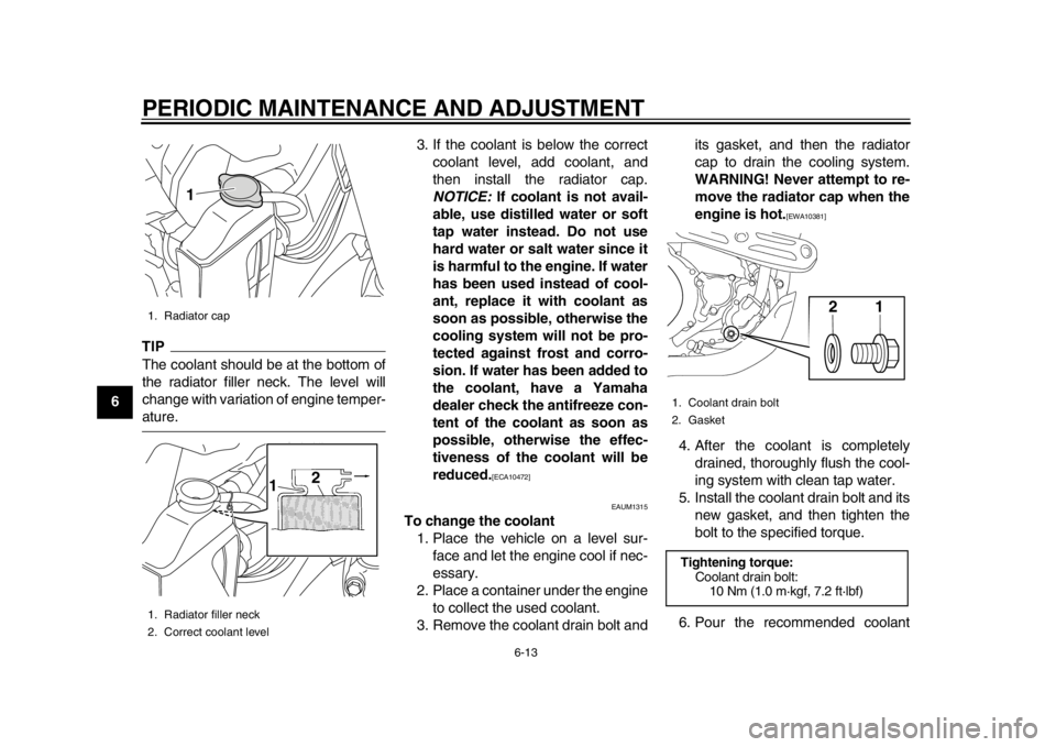
TIPThe coolant should be at the bottom of
the radiator filler neck. The level will
change with variation of engine temper-ature.3. If the coolant is below the correct
coolant level, add coolant, and
then install the radiator cap.
NOTICE: If coolant is not avail-
able, use distilled water or soft
tap water instead. Do not use
hard water or salt water since it
is harmful to the engine. If water
has been used instead of cool-
ant, replace it with coolant as
soon as possible, otherwise the
cooling system will not be pro-
tected against frost and corro-
sion. If water has been added to
the coolant, have a Yamaha
dealer check the antifreeze con-
tent of the coolant as soon as
possible, otherwise the effec-
tiveness of the coolant will be
reduced.
[ECA10472]
EAUM1315
To change the coolant 1. Place the vehicle on a level sur- face and let the engine cool if nec-
essary.
2. Place a container under the engine to collect the used coolant.
3. Remove the coolant drain bolt and its gasket, and then the radiator
cap to drain the cooling system.
WARNING! Never attempt to re-
move the radiator cap when the
engine is hot.
[EWA10381]
4. After the coolant is completely drained, thoroughly flush the cool-
ing system with clean tap water.
5. Install the coolant drain bolt and its new gasket, and then tighten the
bolt to the specified torque.
6. Pour the recommended coolant
1. Radiator cap
1. Radiator filler neck
2. Correct coolant level
1
2
1
1. Coolant drain bolt
2. GasketTightening torque:
Coolant drain bolt:10 Nm (1.0 m·kgf, 7.2 ft·lbf)
21
1DX-9-E1.book 13 ページ 2012年7月31日 火曜日 午前9時31分
Page 57 of 98
PERIODIC MAINTENANCE AND ADJUSTMENT
6-14
2
3
4
567
8
9
into the radiator until it is full.
7. Install the radiator cap, start the engine, let it idle for several min-
utes, and then turn it off.
8. Remove the radiator cap to check the coolant level in the radiator. If
necessary, add sufficient coolant
until it reaches the bottom of the
radiator filler neck, and then install
the radiator cap.
9. Start the engine, and then check the vehicle for coolant leakage. If
coolant is leaking, have a Yamaha
dealer check the cooling system.
EAU52932
Cleaning the air filter element
and check hose The air filter element should be cleaned
or replaced at the intervals specified in
the periodic maintenance and lubrica-
tion chart. Clean or, if necessary, re-
place the air filter element more
frequently if you are riding in unusually
wet or dusty areas. In addition, the air
filter check hose must be frequently
checked and cleaned if necessary.
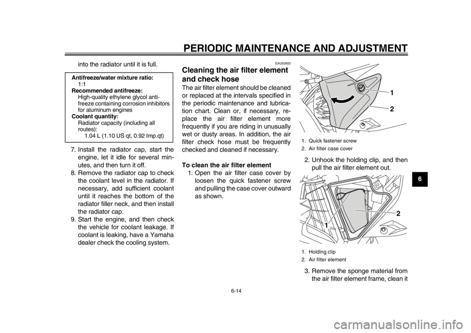
To clean the air filter element1. Open the air filter case cover by loosen the quick fastener screw
and pulling the case cover outward
as shown. 2. Unhook the holding clip, and then
pull the air filter element out.
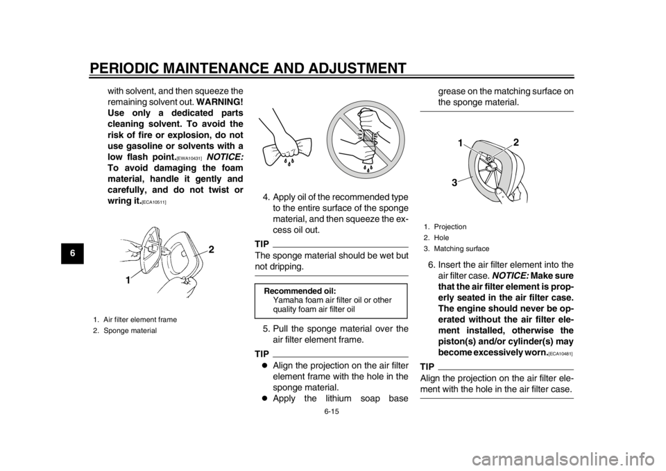
3. Remove the sponge material from the air filter element frame, clean it
Antifreeze/water mixture ratio:1:1
Recommended antifreeze:
High-quality ethylene glycol anti-
freeze containing corrosion inhibitors
for aluminum engines
Coolant quantity: Radiator capacity (including all
routes): 1.04 L (1.10 US qt, 0.92 Imp.qt)
1. Quick fastener screw
2. Air filter case cover
1. Holding clip
2. Air filter element
12
1 2
1DX-9-E1.book 14 ページ 2012年7月31日 火曜日 午前9時31分
Page 58 of 98
PERIODIC MAINTENANCE AND ADJUSTMENT
6-15
1
2
3
4
56
7
8
9with solvent, and then squeeze the
remaining solvent out.
WARNING!
Use only a dedicated parts
cleaning solvent. To avoid the
risk of fire or explosion, do not
use gasoline or solvents with a
low flash point.
[EWA10431]
NOTICE:
To avoid damaging the foam
material, handle it gently and
carefully, and do not twist or
wring it.
[ECA10511]
4. Apply oil of the recommended type
to the entire surface of the sponge
material, and then squeeze the ex-
cess oil out.
TIPThe sponge material should be wet butnot dripping.
5. Pull the sponge material over the air filter element frame.TIP
Align the projection on the air filter
element frame with the hole in the
sponge material.
Apply the lithium soap base grease on the matching surface on
the sponge material.
6. Insert the air filter element into the air filter case. NOTICE: Make sure
that the air filter element is prop-
erly seated in the air filter case.
The engine should never be op-
erated without the air filter ele-
ment installed, otherwise the
piston(s) and/or cylinder(s) may
become excessively worn.
[ECA10481]
TIPAlign the projection on the air filter ele-ment with the hole in the air filter case.
1. Air filter element frame
2. Sponge material
1 2
Recommended oil:
Yamaha foam air filter oil or other
quality foam air filter oil
1. Projection
2. Hole
3. Matching surface
1 23
1DX-9-E1.book 15 ページ 2012年7月31日 火曜日 午前9時31分
Page 59 of 98
PERIODIC MAINTENANCE AND ADJUSTMENT
6-16
2
3
4
567
8
9
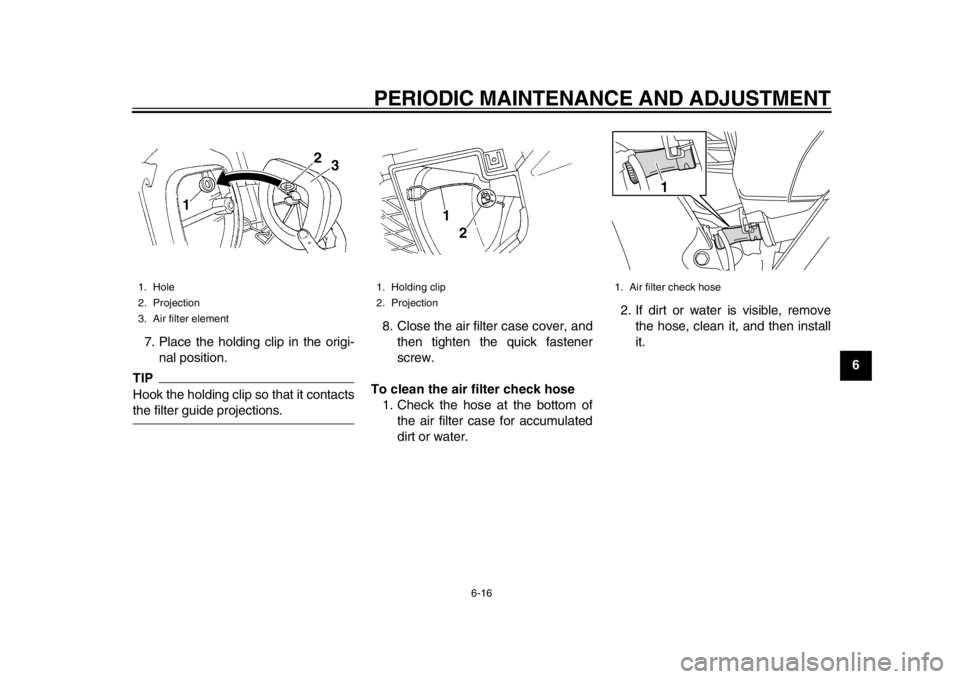
7. Place the holding clip in the origi-
nal position.
TIPHook the holding clip so that it contactsthe filter guide projections. 8. Close the air filter case cover, and
then tighten the quick fastener
screw.
To clean the air filter check hose 1. Check the hose at the bottom of the air filter case for accumulated
dirt or water. 2. If dirt or water is visible, remove
the hose, clean it, and then install
it.1. Hole
2. Projection
3. Air filter element
1 2
3
1. Holding clip
2. Projection
1
2
1. Air filter check hose
1
1DX-9-E1.book 16 ページ 2012年7月31日 火曜日 午前9時31分
Page 60 of 98
PERIODIC MAINTENANCE AND ADJUSTMENT
6-17
1
2
3
4
56
7
8
9
EAU52460
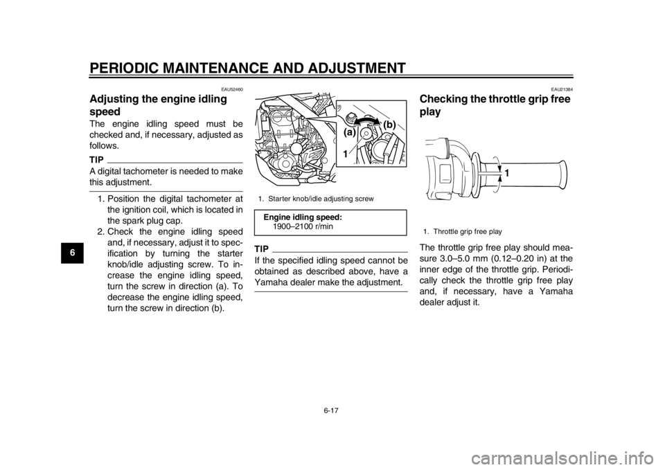
Adjusting the engine idling
speed The engine idling speed must be
checked and, if necessary, adjusted as
follows.TIPA digital tachometer is needed to makethis adjustment.1. Position the digital tachometer at the ignition coil, which is located in
the spark plug cap.
2. Check the engine idling speed and, if necessary, adjust it to spec-
ification by turning the starter
knob/idle adjusting screw. To in-
crease the engine idling speed,
turn the screw in direction (a). To
decrease the engine idling speed,
turn the screw in direction (b).
TIPIf the specified idling speed cannot be
obtained as described above, have aYamaha dealer make the adjustment.
EAU21384
Checking the throttle grip free
play The throttle grip free play should mea-
sure 3.0–5.0 mm (0.12–0.20 in) at the
inner edge of the throttle grip. Periodi-
cally check the throttle grip free play
and, if necessary, have a Yamaha
dealer adjust it.
1. Starter knob/idle adjusting screwEngine idling speed:1900–2100 r/min
1(a)
(b)
1. Throttle grip free play
1
1DX-9-E1.book 17 ページ 2012年7月31日 火曜日 午前9時31分