sensor YAMAHA WR 450F 2016 User Guide
[x] Cancel search | Manufacturer: YAMAHA, Model Year: 2016, Model line: WR 450F, Model: YAMAHA WR 450F 2016Pages: 426, PDF Size: 10.86 MB
Page 93 of 426

CABLE ROUTING DIAGRAM
2-42
1. Clutch switch lead
2. Engine stop switch lead
3. Clutch cable
4. Brake hose guide
5. Headlight lead
6. Speed sensor lead
7. Indicator light coupler
8. Meter assembly optional switch coupler
9. Meter assembly coupler
10. Speed sensor coupler
11. Start switch lead
12. Plastic band
13. Throttle cable
14. Front brake hose
A. Route the throttle cable, clutch cable, clutch switch lead, engine stop switch lead and start
switch lead between the cable guide of the meter
bracket and handle crown. The cables and leads
may be routed in any order.
B. Clamp the wire harness, clutch switch lead and start switch lead to the meter bracket. The clamp
shall be located at a pos ition where there is no
slack with the handle turned fully to the left.
C. Connect the headlight lead to the headlight.
D. Clamp the start switch lead to the handlebar by the plastic band.
E. Clamp the engine stop switch lead and clutch switch lead to the handlebar by the plastic band.
F. 40°±10°
G. Vertical direction
H. Pass the engine stop switch lead under the han- dlebar.
Page 139 of 426
ELECTRICAL SYSTEM
3-41
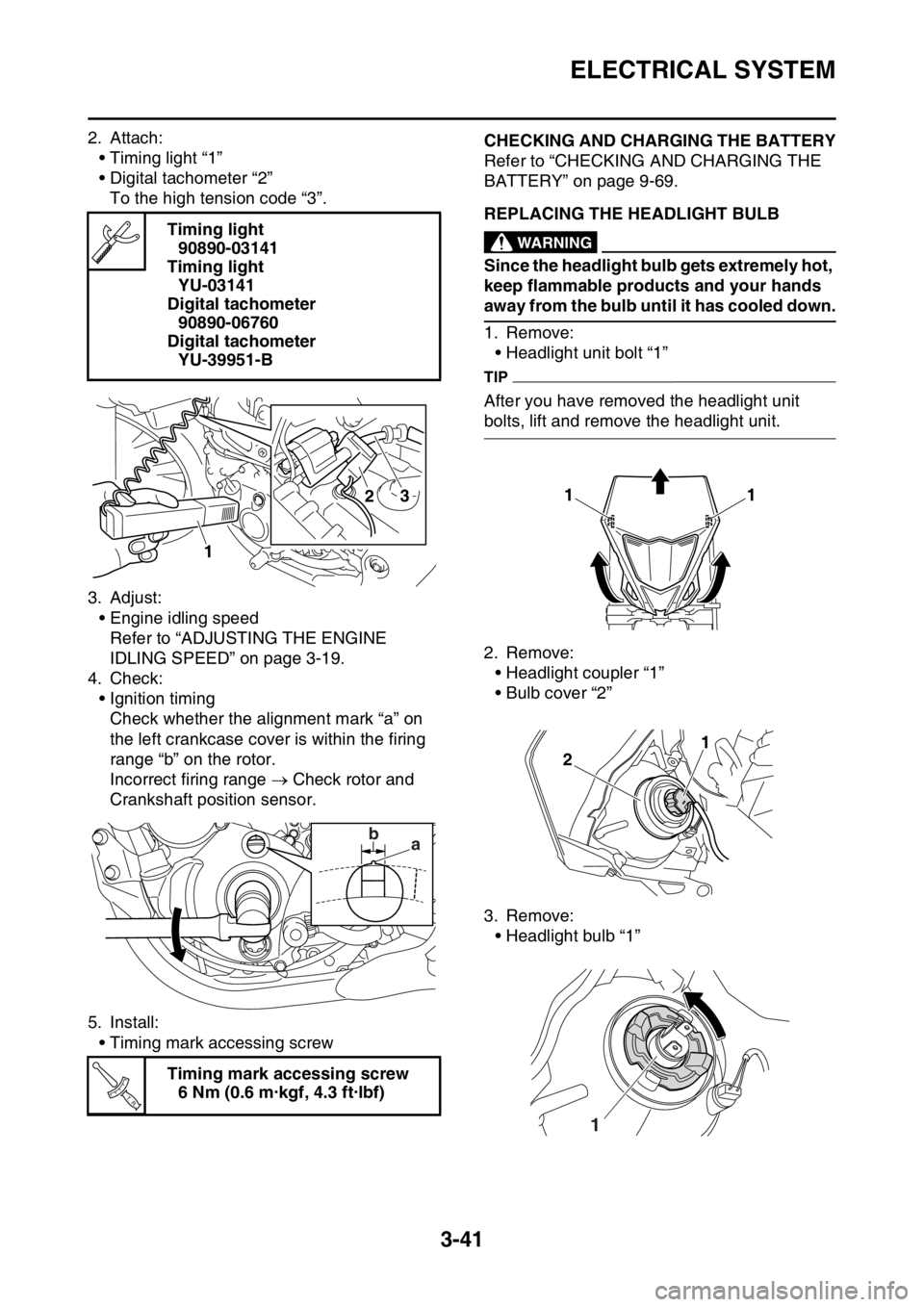
2. Attach:• Timing light “1”
• Digital tachometer “2”To the high tension code “3”.
3. Adjust: • Engine idling speedRefer to “ADJUSTING THE ENGINE
IDLING SPEED” on page 3-19.
4. Check: • Ignition timingCheck whether the alignment mark “a” on
the left crankcase cover is within the firing
range “b” on the rotor.
Incorrect firing range Check rotor and
Crankshaft position sensor.
5. Install: • Timing mark accessing screwEAS2GC1133CHECKING AND CHARGING THE BATTERY
Refer to “CHECKING AND CHARGING THE
BATTERY” on page 9-69.
EAS2GC1134REPLACING THE HEADLIGHT BULBEWA
WARNING
Since the headlight bulb gets extremely hot,
keep flammable products and your hands
away from the bulb until it has cooled down.
1. Remove:• Headlight unit bolt “1”
TIP
After you have removed the headlight unit
bolts, lift and remove the headlight unit.
2. Remove:
• Headlight coupler “1”
• Bulb cover “2”
3. Remove: • Headlight bulb “1”
Timing light
90890-03141
Timing light YU-03141
Digital tachometer 90890-06760
Digital tachometer YU-39951-B
Timing mark accessing screw 6 Nm (0.6 m·kgf, 4.3 ft·lbf)
2
1
3
ba
T R..
11
1
2
1
Page 154 of 426
GENERAL CHASSIS
5-2
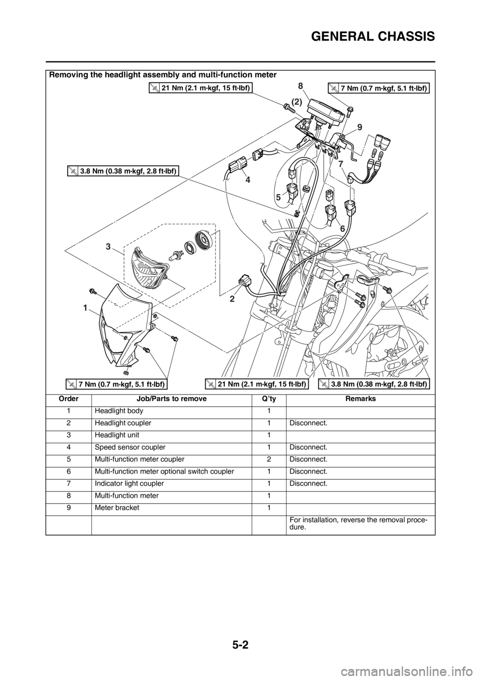
Removing the headlight assembly and multi-function meter
OrderJob/Parts to remove Q’tyRemarks
1 Headlight body 1
2 Headlight coupler 1 Disconnect.
3 Headlight unit 1
4 Speed sensor coupler 1 Disconnect.
5 Multi-function meter coupler 2 Disconnect.
6 Multi-function meter optional switch coupler 1 Disconnect.
7 Indicator light coupler 1 Disconnect.
8 Multi-function meter 1
9 Meter bracket 1
For installation, reverse the removal proce-
dure.
4 (2)
6
7
8
9
5
1
3 2
21 Nm (2.1 m kgf, 15 ft Ibf)T.R.3.8 Nm (0.38 m kgf, 2.8 ft Ibf)T.R.
3.8 Nm (0.38 m kgf, 2.8 ft Ibf)T.R.
21 Nm (2.1 m kgf, 15 ft Ibf)T.R.
7 Nm (0.7 m kgf, 5.1 ft Ibf)T.R.
7 Nm (0.7 m kgf, 5.1 ft Ibf)T.R.
Page 156 of 426
FRONT WHEEL
5-4
EAS2GC1154
FRONT WHEEL
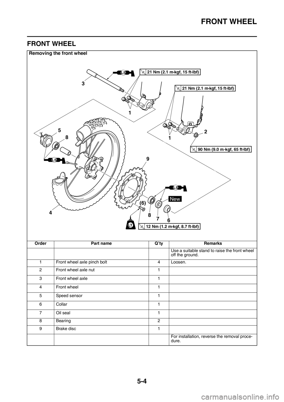
Removing the front wheel
OrderPart name Q’tyRemarks
Use a suitable stand to raise the front wheel
off the ground.
1 Front wheel axle pinch bolt 4 Loosen.
2 Front wheel axle nut 1
3 Front wheel axle 1
4 Front wheel 1
5 Speed sensor 1
6Collar 1
7 Oil seal 1
8 Bearing 2
9 Brake disc 1
For installation, reverse the removal proce-
dure.
12 Nm (1.2 m kgf, 8.7 ft Ibf)T.R.
New
LT
LS
LS
LS
8
7
8
(6)
9
1 2
1
3
21 Nm (2.1 m kgf, 15 ft Ibf)T.R.
21 Nm (2.1 m kgf, 15 ft Ibf)T.R.
4
90 Nm (9.0 m kgf, 65 ft lbf)T.R.
5
6
Page 159 of 426
FRONT WHEEL
5-7
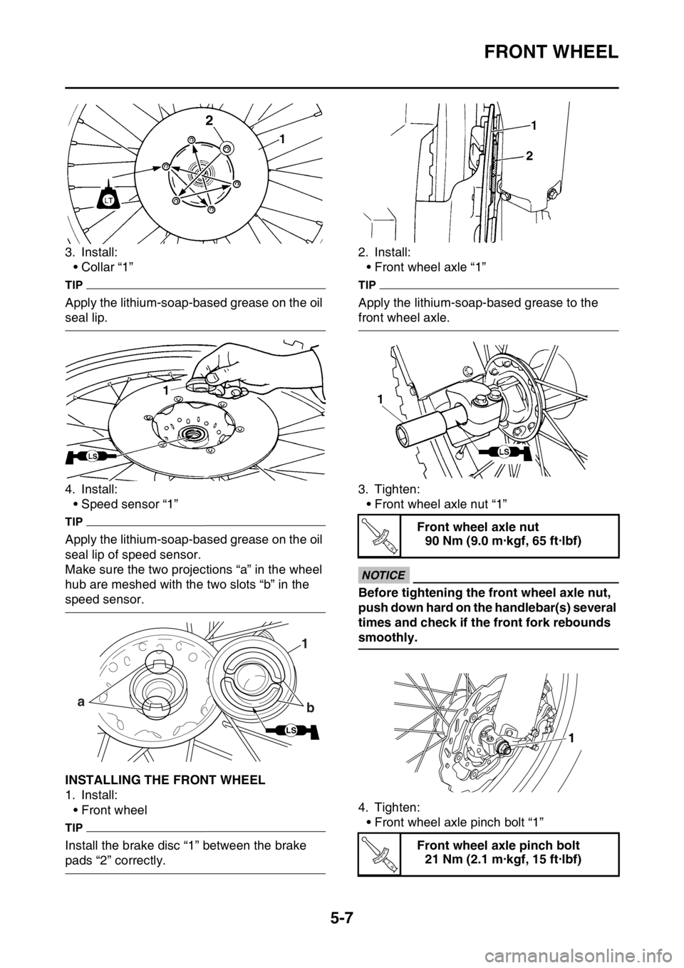
3. Install:• Collar “1”
TIP
Apply the lithium-soap-based grease on the oil
seal lip.
4. Install:
• Speed sensor “1”
TIP
Apply the lithium-soap-based grease on the oil
seal lip of speed sensor.
Make sure the two projections “a” in the wheel
hub are meshed with the two slots “b” in the
speed sensor.
EAS2GC1159INSTALLING THE FRONT WHEEL
1. Install:• Front wheel
TIP
Install the brake disc “1” between the brake
pads “2” correctly. 2. Install:
• Front wheel axle “1”
TIP
Apply the lithium-soap-based grease to the
front wheel axle.
3. Tighten:
• Front wheel axle nut “1”
ECA
NOTICE
Before tightening the front wheel axle nut,
push down hard on the handlebar(s) several
times and check if the front fork rebounds
smoothly.
4. Tighten:• Front wheel axle pinch bolt “1”1
a b
LS
Front wheel axle nut
90 Nm (9.0 m·kgf, 65 ft·lbf)
Front wheel axle pinch bolt 21 Nm (2.1 m·kgf, 15 ft·lbf)
T R..
1
T R..
Page 203 of 426
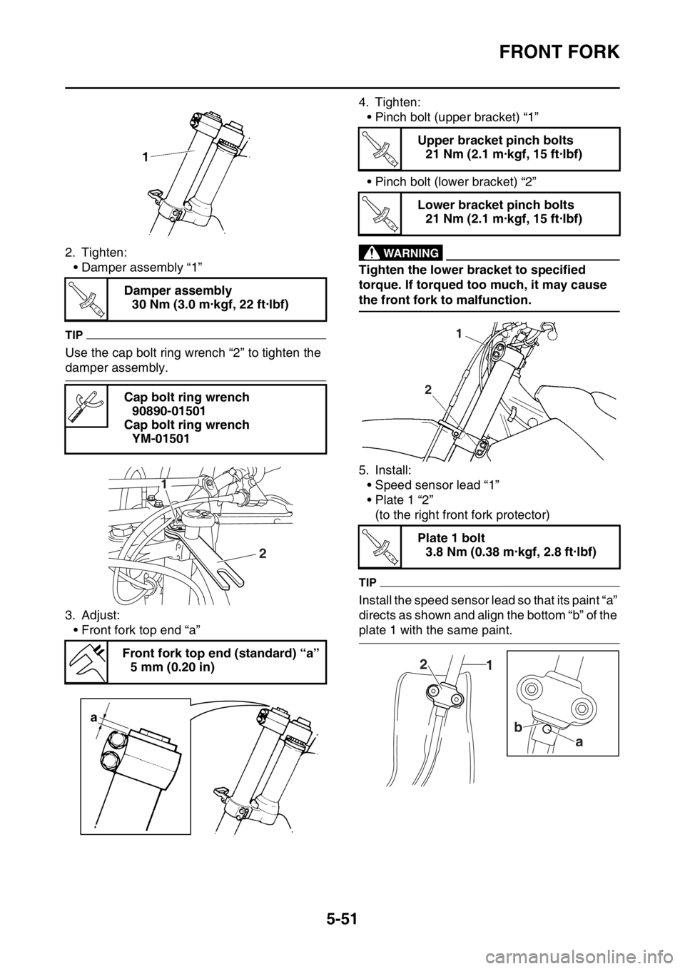
FRONT FORK
5-51
2. Tighten:• Damper assembly “1”
TIP
Use the cap bolt ring wrench “2” to tighten the
damper assembly.
3. Adjust:
• Front fork top end “a” 4. Tighten:
• Pinch bolt (upper bracket) “1”
• Pinch bolt (lower bracket) “2”
EWA
WARNING
Tighten the lower bracket to specified
torque. If torqued too much, it may cause
the front fork to malfunction.
5. Install:• Speed sensor lead “1”
• Plate 1 “2”(to the right front fork protector)
TIP
Install the speed sensor lead so that its paint “a”
directs as shown and align the bottom “b” of the
plate 1 with the same paint.
Damper assembly
30 Nm (3.0 m·kgf, 22 ft·lbf)
Cap bolt ring wrench 90890-01501
Cap bolt ring wrench YM-01501
Front fork top end (standard) “a” 5 mm (0.20 in)
T R..
2
1
a
Upper bracket pinch bolts21 Nm (2.1 m·kgf, 15 ft·lbf)
Lower bracket pinch bolts 21 Nm (2.1 m·kgf, 15 ft·lbf)
Plate 1 bolt 3.8 Nm (0.38 m·kgf, 2.8 ft·lbf)
T R..
T R..
2 1
T R..
1
2
a
b
Page 204 of 426
FRONT FORK
5-52
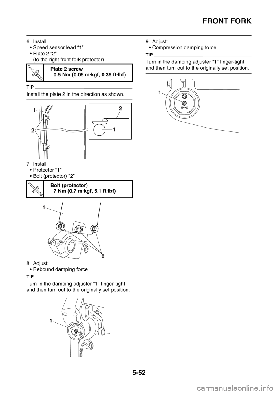
6. Install:• Speed sensor lead “1”
• Plate 2 “2”(to the right front fork protector)
TIP
Install the plate 2 in the direction as shown.
7. Install:• Protector “1”
• Bolt (protector) “2”
8. Adjust: • Rebound damping force
TIP
Turn in the damping adjuster “1” finger-tight
and then turn out to the originally set position. 9. Adjust:
• Compression damping force
TIP
Turn in the damping adjuster “1” finger-tight
and then turn out to the originally set position.
Plate 2 screw
0.5 Nm (0.05 m·kgf, 0.36 ft·lbf)
Bolt (protector) 7 Nm (0.7 m·kgf, 5.1 ft·lbf)
T R..
1
2 12
T R..
1
2
1
1
Page 209 of 426
STEERING HEAD
5-57
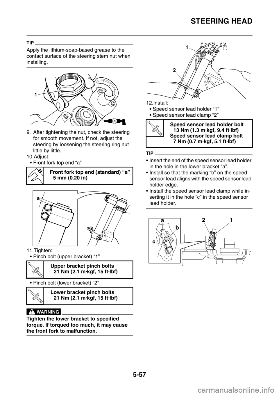
TIP
Apply the lithium-soap-based grease to the
contact surface of the steering stem nut when
installing.
9. After tightening the nut, check the steering for smooth movement. If not, adjust the
steering by loosening the steering ring nut
little by little.
10.Adjust:
• Front fork top end “a”
11.Tighten: • Pinch bolt (upper bracket) “1”
• Pinch bolt (lower bracket) “2”
EWA
WARNING
Tighten the lower bracket to specified
torque. If torqued too much, it may cause
the front fork to malfunction. 12.Install:
• Speed sensor lead holder “1”
• Speed sensor lead clamp “2”
TIP
• Insert the end of the speed sensor lead holder
in the hole in the lower bracket “a”.
• Install so that the marking “b” on the speed sensor lead aligns with the speed sensor lead
holder edge.
• Install the speed sens or lead clamp while in-
serting it in the hole “c” in the speed sensor
lead holder.
Front fork top end (standard) “a”
5 mm (0.20 in)
Upper bracket pinch bolts 21 Nm (2.1 m·kgf, 15 ft·lbf)
Lower bracket pinch bolts 21 Nm (2.1 m·kgf, 15 ft·lbf)
a
T R..
T R..
Speed sensor lead holder bolt13 Nm (1.3 m·kgf, 9.4 ft·lbf)
Speed sensor lead clamp bolt 7 Nm (0.7 m·kgf, 5.1 ft·lbf)
2 1
T R..
Page 230 of 426
ENGINE REMOVAL
6-3
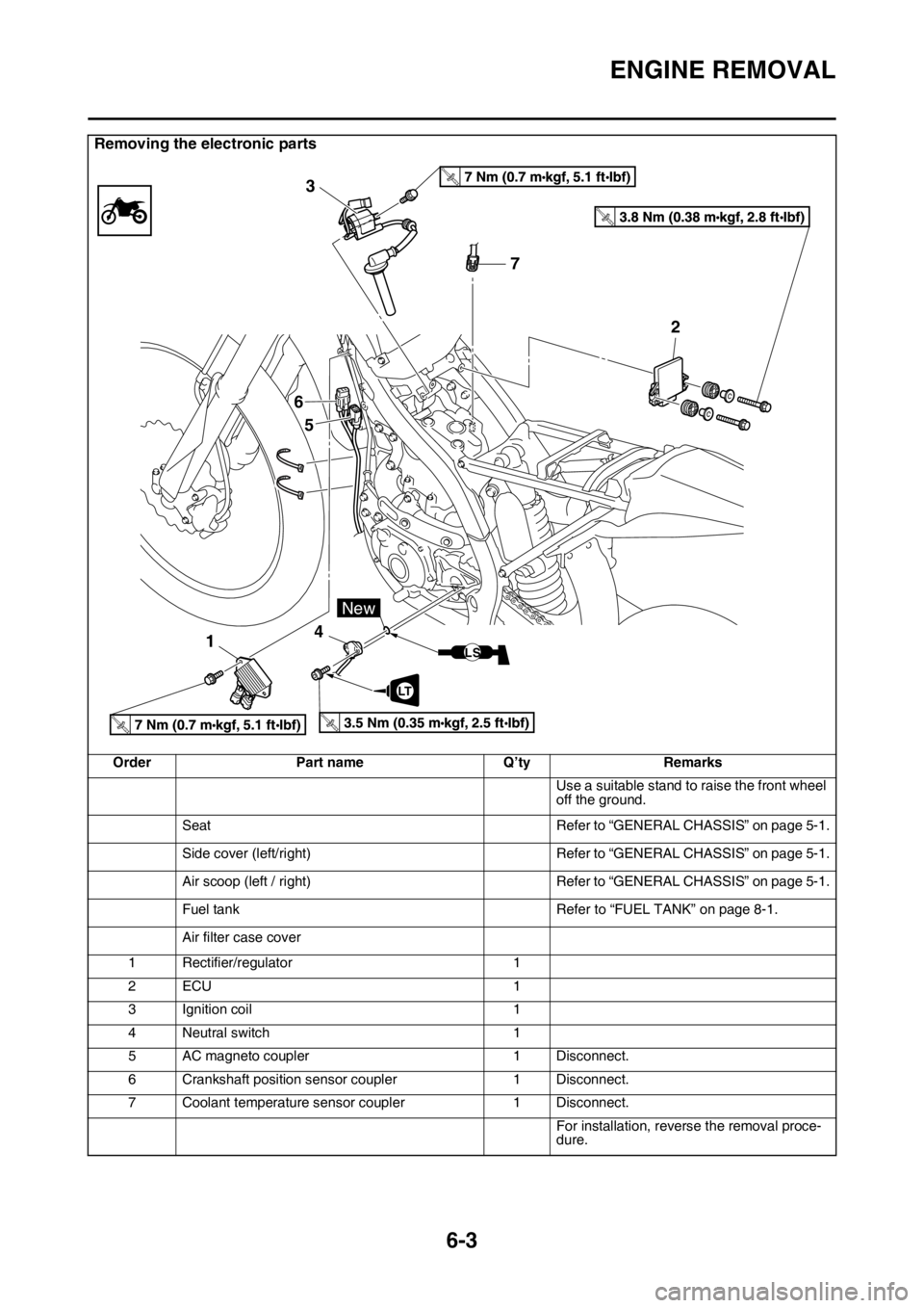
Removing the electronic parts
OrderPart name Q’tyRemarks
Use a suitable stand to raise the front wheel
off the ground.
Seat Refer to “GENERAL CHASSIS” on page 5-1.
Side cover (left/right) Refer to “GENERAL CHASSIS” on page 5-1.
Air scoop (left / right) Refer to “GENERAL CHASSIS” on page 5-1.
Fuel tank Refer to “FUEL TANK” on page 8-1.
Air filter case cover
1 Rectifier/regulator 1
2ECU 1
3 Ignition coil 1
4 Neutral switch 1
5 AC magneto coupler 1 Disconnect.
6 Crankshaft position sensor coupler 1 Disconnect.
7 Coolant temperature sens or coupler1 Disconnect.
For installation, reverse the removal proce-
dure.
T.R.
T.R.
T.R.T.R.
7
3
6 5
1 4 2
LT
New
LS
Page 291 of 426
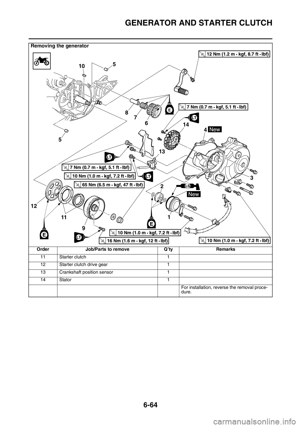
GENERATOR AND STARTER CLUTCH
6-64
11 Starter clutch1
12 Starter clutch drive gear 1
13 Crankshaft position sensor 1
14 Stator 1
For installation, reverse the removal proce-
dure.
Removing the generator
Order Job/Parts to remove Q’tyRemarks
T R..
T R..
T R..
5
5 10
87
6
21
13 3
4
11 9
12
T R..
T R..
T R..LT
LT
T R..
T R..
14
LT
LT