YAMAHA XENTER 125 2012 Workshop Manual
Manufacturer: YAMAHA, Model Year: 2012, Model line: XENTER 125, Model: YAMAHA XENTER 125 2012Pages: 84, PDF Size: 1.09 MB
Page 51 of 84
![YAMAHA XENTER 125 2012 Workshop Manual 1
2
3
4
5
6
7
8
9
6-14
EAU1722A
PERIODIC MAINTENANCE AND ADJUSTMENT
engine is hot.
[EWA15161]
5. Add coolant or distilled water to
raise the coolant to the maximum
level mark, and install the cool- YAMAHA XENTER 125 2012 Workshop Manual 1
2
3
4
5
6
7
8
9
6-14
EAU1722A
PERIODIC MAINTENANCE AND ADJUSTMENT
engine is hot.
[EWA15161]
5. Add coolant or distilled water to
raise the coolant to the maximum
level mark, and install the cool-](/img/51/52543/w960_52543-50.png)
1
2
3
4
5
6
7
8
9
6-14
EAU1722A
PERIODIC MAINTENANCE AND ADJUSTMENT
engine is hot.
[EWA15161]
5. Add coolant or distilled water to
raise the coolant to the maximum
level mark, and install the cool-
ant reservoir cap.
NOTICE:
If
coolant is not available, use
distilled water or soft tap water
instead. Do not use hard water
or salt water since it is harmful
to the engine. If water has been
used instead of coolant, re-
place it with coolant as soon as
possible, otherwise the cooling
system will not be protected
against frost and corrosion. If
water has been added to the
coolant, have a Yamaha dealer
check the antifreeze content
of the coolant as soon as pos-
sible, otherwise the effective-
ness of the coolant will be
reduced.
[ECA10472]
Coolant reservoir capacity:
0.25 L (0.26 US qt, 0.22 Imp.qt)
6. Close the seat.
EAU33031
Changing the coolant
The coolant must be changed at the
intervals specified in the periodic
maintenance and lubrication chart.
Have a Yamaha dealer change the
coolant. WARNING! Never attempt
to remove the radiator cap when
the engine is hot.
[EWA10381]
reading.
2. Open the seat. (See page 3-11.)
3. Check the coolant level in the
coolant reservoir.
12
1. Maximum level mark
2. Minimum level markTIPThe coolant should be between the
minimum and maximum level marks.
4. If the coolant is at or below the
minimum level mark, remove
the reservoir cap. WARNING!
Remove only the coolant res-
ervoir cap. Never attempt to re-
move the radiator cap when the
53B-F8199-E0_CS.indd 6-1453B-F8199-E0_CS.indd 6-14
2011/11/01 12:32:092011/11/01 12:32:09
Process BlackProcess Black
Page 52 of 84
1
2
3
4
5
6
7
8
9
6-15
EAU1722A
PERIODIC MAINTENANCE AND ADJUSTMENT
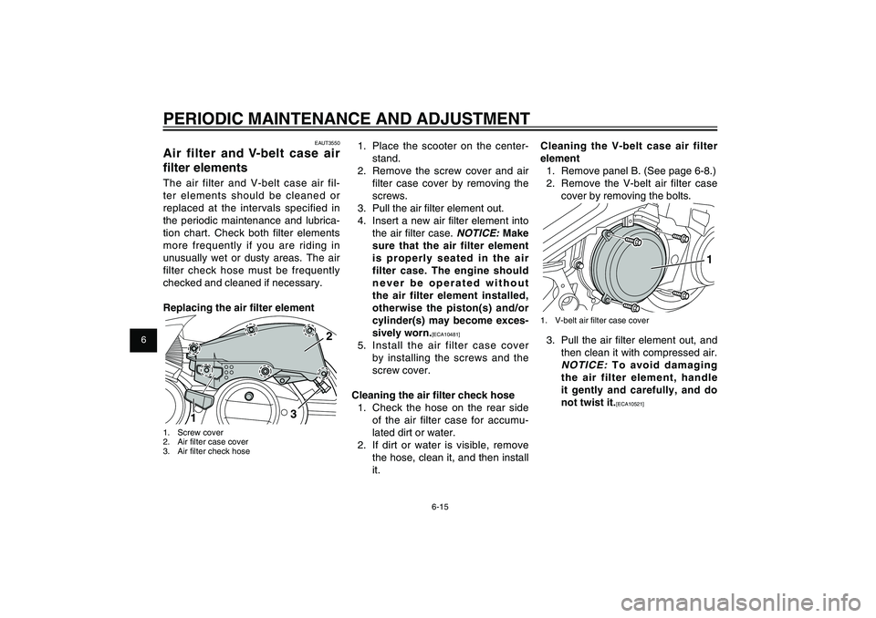
1. Place the scooter on the center-
stand.
2. Remove the screw cover and air
fi lter case cover by removing the
screws.
3. Pull the air fi lter element out.
4. Insert a new air fi lter element into
the air fi lter case.
NOTICE:
Make
sure that the air filter element
is properly seated in the air
filter case. The engine should
never be operated without
the air filter element installed,
otherwise the piston(s) and/or
cylinder(s) may become exces-
sively worn.
[ECA10481]
5. Install the air filter case cover
by installing the screws and the
screw cover.
Cleaning the air � lter check hose
1. Check the hose on the rear side
of the air filter case for accumu-
lated dirt or water.
2. If dirt or water is visible, remove
the hose, clean it, and then install
it.Cleaning the V-belt case air filter
element
1. Remove panel B. (See page 6-8.)
2. Remove the V-belt air filter case
cover by removing the bolts.
1
1. V-belt air fi lter case cover3. Pull the air fi lter element out, and
then clean it with compressed air.
NOTICE:
To avoid damaging
the air filter element, handle
it gently and carefully, and do
not twist it.[ECA10521] EAUT3550
Air filter and V-belt case air
� lter elementsThe air filter and V-belt case air fil-
ter elements should be cleaned or
replaced at the intervals specified in
the periodic maintenance and lubrica-
tion chart. Check both filter elements
more frequently if you are riding in
unusually wet or dusty areas. The air
filter check hose must be frequently
checked and cleaned if necessary.
Replacing the air � lter element
2
3
1
1. Screw cover
2. Air fi lter case cover
3. Air fi lter check hose
53B-F8199-E0_CS.indd 6-1553B-F8199-E0_CS.indd 6-15
2011/11/01 12:32:092011/11/01 12:32:09
Process BlackProcess Black
Page 53 of 84
1
2
3
4
5
6
7
8
9
6-16
EAU1722A
PERIODIC MAINTENANCE AND ADJUSTMENT
EAU21384
Checking the throttle grip
free play
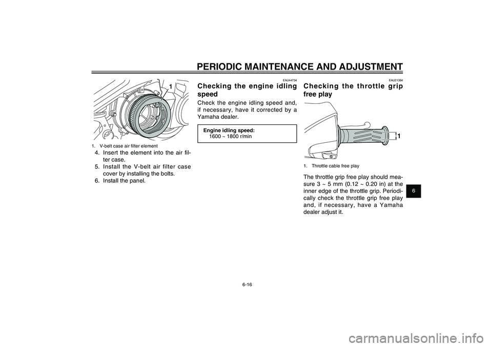
1
1. Throttle cable free playThe throttle grip free play should mea-
sure 3 ~ 5 mm (0.12 ~ 0.20 in) at the
inner edge of the throttle grip. Periodi-
cally check the throttle grip free play
and, if necessary, have a Yamaha
dealer adjust it.
EAU44734
Checking the engine idling
speedCheck the engine idling speed and,
if necessary, have it corrected by a
Yamaha dealer.Engine idling speed:
1600 ~ 1800 r/min
1
1. V-belt case air fi lter element4. Insert the element into the air fi l-
ter case.
5. Install the V-belt air filter case
cover by installing the bolts.
6. Install the panel.
53B-F8199-E0_CS.indd 6-1653B-F8199-E0_CS.indd 6-16
2011/11/01 12:32:102011/11/01 12:32:10
Process BlackProcess Black
Page 54 of 84
1
2
3
4
5
6
7
8
9
6-17
EAU1722A
PERIODIC MAINTENANCE AND ADJUSTMENT
proved for this model.
Tire air pressure (measured on cold
tires):
Up to 90 kg (198 lb):
Front:
175 kPa (1.75 kgf/cm
2, 25 psi)
Rear:
200 kPa (2.00 kgf/cm2, 29 psi)
90 kg (198 lb) to maximum load:
Front:
175 kPa (1.75 kgf/cm2, 25 psi)
Rear:
225 kPa (2.25 kgf/cm2, 33 psi)
Maximum load*:
179 kg (395 lb)
*Total weight of rider, passenger,
cargo and accessories
EWA10511
WARNING
Never overload your vehicle. Op-
eration of an overloaded vehicle
could cause an accident.
EAUT2142
TiresTo maximize the performance, dura-
bility, and safe operation of your ve-
hicle, note the following points regard-
ing the specifi ed tires.
Tire air pressure
The tire air pressure should be
checked and, if necessary, adjusted
before each ride.
EWA10503
WARNING
Operation of this vehicle with im-
proper tire pressure may cause
severe injury or death from loss of
control.● The tire air pressure must be
checked and adjusted on cold
tires (i.e., when the tempera-
ture of the tires equals the am-
bient temperature).● The tire air pressure must be
adjusted in accordance with
the riding speed and with the
total weight of rider, passen-
ger, cargo, and accessories ap-
EAU21401
Valve clearanceThe valve clearance changes with
use, resulting in improper air-fuel mix-
ture and/or engine noise. To prevent
this from occurring, the valve clear-
ance must be adjusted by a Yamaha
dealer at the intervals specifi ed in the
periodic maintenance and lubrication
chart.
53B-F8199-E0_CS.indd 6-1753B-F8199-E0_CS.indd 6-17
2011/11/01 12:32:102011/11/01 12:32:10
Process BlackProcess Black
Page 55 of 84
1
2
3
4
5
6
7
8
9
6-18
EAU1722A
PERIODIC MAINTENANCE AND ADJUSTMENT
necessary professional knowl-
edge and experience.
Tire information
This model is equipped with tubeless
tires.
After extensive tests, only the tires
listed below have been approved for
this model by Yamaha Motor Co., Ltd.Front tire:
Size:
100/80-16M/C 50P
Manufacturer/model:
DURO/DM1157F
Rear tire:
Size:
120/80-16M/C 60P
Manufacturer/model:
DURO/DM1157
EWA10470
WARNING
● Have a Yamaha dealer replace
excessively worn tires. Besides
being illegal, operating the
vehicle with excessively worn
tires decreases riding stability
and can lead to loss of control.● The replacement of all wheel
and brake related parts, includ-
ing the tires, should be left to
a Yamaha dealer, who has the
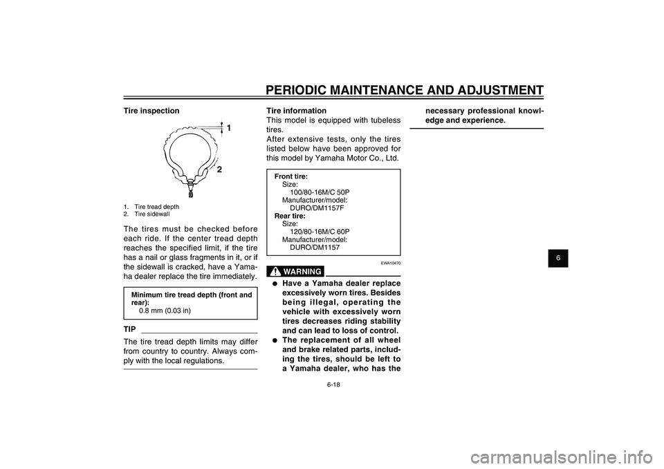
Tire inspection
1
2
1. Tire tread depth
2. Tire sidewallThe tires must be checked before
each ride. If the center tread depth
reaches the specified limit, if the tire
has a nail or glass fragments in it, or if
the sidewall is cracked, have a Yama-
ha dealer replace the tire immediately.Minimum tire tread depth (front and
rear):
0.8 mm (0.03 in)TIPThe tire tread depth limits may differ
from country to country. Always com-
ply with the local regulations.
53B-F8199-E0_CS.indd 6-1853B-F8199-E0_CS.indd 6-18
2011/11/01 12:32:102011/11/01 12:32:10
Process BlackProcess Black
Page 56 of 84
1
2
3
4
5
6
7
8
9
6-19
EAU1722A
PERIODIC MAINTENANCE AND ADJUSTMENT
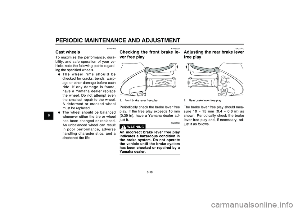
EAU22170
Adjusting the rear brake lever
free play11. Rear brake lever free playThe brake lever free play should mea-
sure 10 ~ 15 mm (0.4 ~ 0.6 in) as
shown. Periodically check the brake
lever free play and, if necessary, ad-
just it as follows.
EAUS2001
Checking the front brake le-
ver free play
1
1. Front brake lever free playPeriodically check the brake lever free
play. If the free play exceeds 10 mm
(0.39 in), have a Yamaha dealer ad-
just it.
EWA10641
WARNING
An incorrect brake lever free play
indicates a hazardous condition in
the brake system. Do not operate
the vehicle until the brake system
has been checked or repaired by a
Yamaha dealer.
EAU21962
Cast wheelsTo maximize the performance, dura-
bility, and safe operation of your ve-
hicle, note the following points regard-
ing the specifi ed wheels.● The wheel rims should be
checked for cracks, bends, warp-
age or other damage before each
ride. If any damage is found,
have a Yamaha dealer replace
the wheel. Do not attempt even
the smallest repair to the wheel.
A deformed or cracked wheel
must be replaced.● The wheel should be balanced
whenever either the tire or wheel
has been changed or replaced.
An unbalanced wheel can result
in poor performance, adverse
handling characteristics, and a
shortened tire life.
53B-F8199-E0_CS.indd 6-1953B-F8199-E0_CS.indd 6-19
2011/11/01 12:32:102011/11/01 12:32:10
Process BlackProcess Black
Page 57 of 84
1
2
3
4
5
6
7
8
9
6-20
EAU1722A
PERIODIC MAINTENANCE AND ADJUSTMENT
brake pad has worn to the point that
the wear indicator groove has almost
disappeared, have a Yamaha dealer
replace the brake pads as a set.
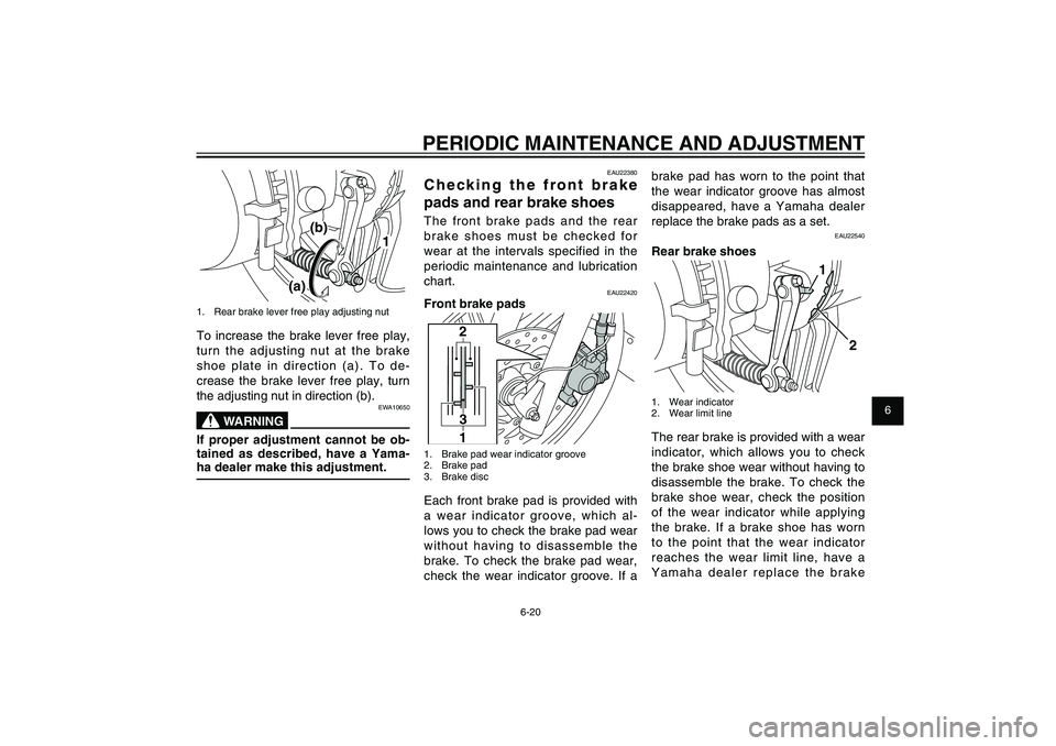
EAU22540
Rear brake shoes
1
2
1. Wear indicator
2. Wear limit lineThe rear brake is provided with a wear
indicator, which allows you to check
the brake shoe wear without having to
disassemble the brake. To check the
brake shoe wear, check the position
of the wear indicator while applying
the brake. If a brake shoe has worn
to the point that the wear indicator
reaches the wear limit line, have a
Yamaha dealer replace the brake
EAU22380
Checking the front brake
pads and rear brake shoesThe front brake pads and the rear
brake shoes must be checked for
wear at the intervals specified in the
periodic maintenance and lubrication
chart.
EAU22420
Front brake pads
2
3
1
1. Brake pad wear indicator groove
2. Brake pad
3. Brake discEach front brake pad is provided with
a wear indicator groove, which al-
lows you to check the brake pad wear
without having to disassemble the
brake. To check the brake pad wear,
check the wear indicator groove. If a
(a)(b)
1
1. Rear brake lever free play adjusting nutTo increase the brake lever free play,
turn the adjusting nut at the brake
shoe plate in direction (a). To de-
crease the brake lever free play, turn
the adjusting nut in direction (b).
EWA10650
WARNING
If proper adjustment cannot be ob-
tained as described, have a Yama-
ha dealer make this adjustment.
53B-F8199-E0_CS.indd 6-2053B-F8199-E0_CS.indd 6-20
2011/11/01 12:32:102011/11/01 12:32:10
Process BlackProcess Black
Page 58 of 84
1
2
3
4
5
6
7
8
9
6-21
EAU1722A
PERIODIC MAINTENANCE AND ADJUSTMENT
tem, reducing braking perfor-
mance.
● Clean the filler cap before re-
moving. Use only DOT 4 brake
� uid from a sealed container.● Use only the specified brake
fluid; otherwise, the rubber
seals may deteriorate, causing
leakage.● Refill with the same type of
brake � uid. Adding a brake � u-
id other than DOT 4 may result
in a harmful chemical reaction.● Be careful that water does not
enter the brake fluid reser-
voir when refilling. Water will
significantly lower the boiling
point of the fluid and may re-
sult in vapor lock.
ECA17640
NOTICEBrake fluid may damage painted
surfaces or plastic parts. Always
clean up spilled � uid immediately.
As the brake pads wear, it is normal
for the brake fluid level to gradually
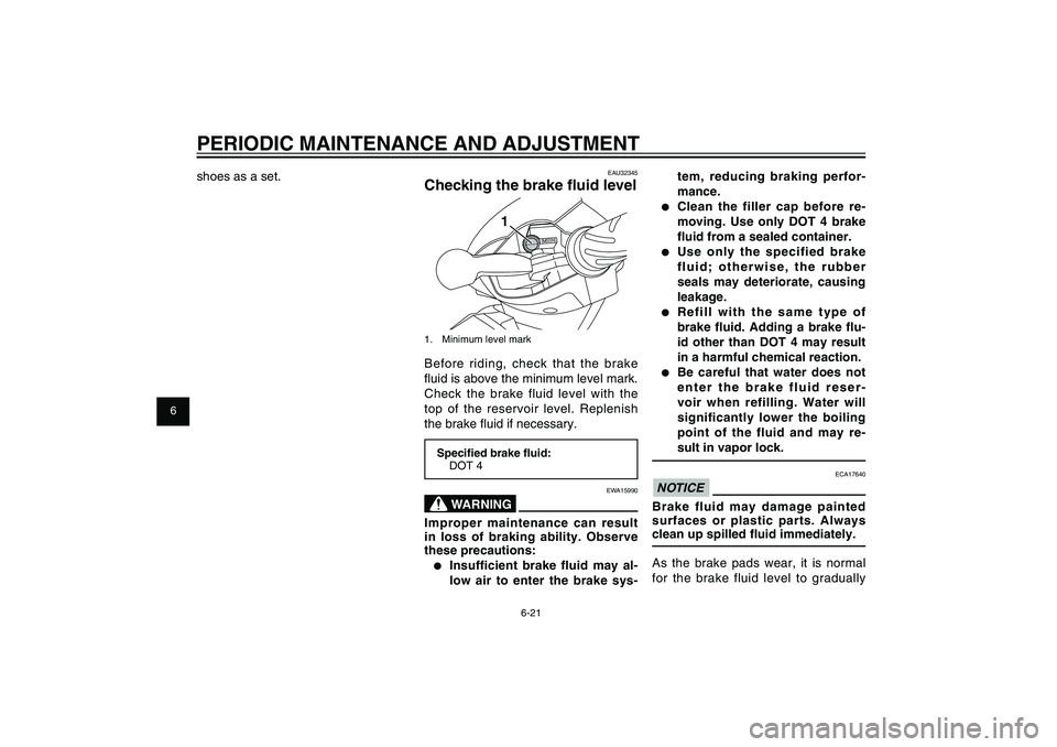
EAU32345
Checking the brake � uid level
1
1. Minimum level markBefore riding, check that the brake
fl uid is above the minimum level mark.
Check the brake fluid level with the
top of the reservoir level. Replenish
the brake fl uid if necessary.Speci� ed brake � uid:
DOT 4
EWA15990
WARNING
Improper maintenance can result
in loss of braking ability. Observe
these precautions:● Insufficient brake fluid may al-
low air to enter the brake sys- shoes as a set.
53B-F8199-E0_CS.indd 6-2153B-F8199-E0_CS.indd 6-21
2011/11/01 12:32:102011/11/01 12:32:10
Process BlackProcess Black
Page 59 of 84
1
2
3
4
5
6
7
8
9
6-22
EAU1722A
PERIODIC MAINTENANCE AND ADJUSTMENT
EAU23095
Checking and lubricating the
cablesThe operation of all control cables
and the condition of the cables should
be checked before each ride, and
the cables and cable ends should be
lubricated if necessary. If a cable is
damaged or does not move smoothly,
have a Yamaha dealer check or re-
place it. WARNING! Damage to the
outer housing of cables may result
in internal rusting and cause in-
terference with cable movement.
Replace damaged cables as soon
as possible to prevent unsafe
conditions.
[EWA10711]
Recommended lubricant:
Yamaha Chain and Cable Lube or
engine oil
EAU22721
Changing the brake � uidHave a Yamaha dealer change the
brake fl uid at the intervals specifi ed in
the TIP after the periodic maintenance
and lubrication chart. In addition, have
the oil seals of the brake master cyl-
inder and caliper as well as the brake
hose replaced at the intervals listed
below or whenever they are damaged
or leaking.● Oil seals: Replace every two
years.● Brake hose: Replace every four
years. go down. A low brake fl uid level may
indicate worn brake pads and/or brake
system leakage; therefore, be sure to
check the brake pads for wear and the
brake system for leakage. If the brake
fl uid level goes down suddenly, have
a Yamaha dealer check the cause be-
fore further riding.
53B-F8199-E0_CS.indd 6-2253B-F8199-E0_CS.indd 6-22
2011/11/01 12:32:102011/11/01 12:32:10
Process BlackProcess Black
Page 60 of 84
1
2
3
4
5
6
7
8
9
6-23
EAU1722A
PERIODIC MAINTENANCE AND ADJUSTMENT
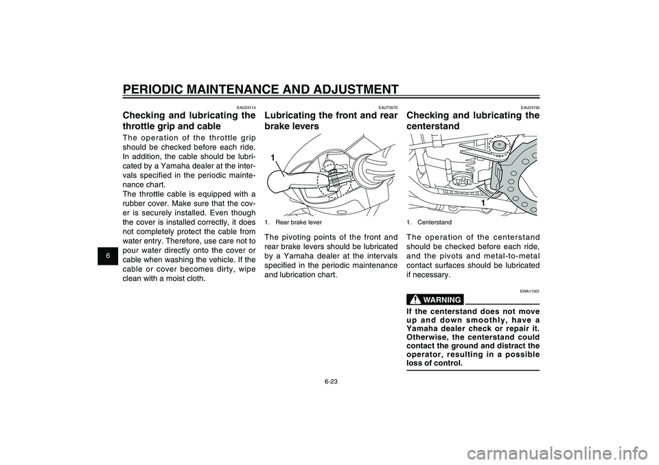
EAU23192
Checking and lubricating the
centerstand
1
1. CenterstandThe operation of the centerstand
should be checked before each ride,
and the pivots and metal-to-metal
contact surfaces should be lubricated
if necessary.
EWA11301
WARNING
If the centerstand does not move
up and down smoothly, have a
Yamaha dealer check or repair it.
Otherwise, the centerstand could
contact the ground and distract the
operator, resulting in a possible
loss of control.
EAUT3570
Lubricating the front and rear
brake levers11. Rear brake leverThe pivoting points of the front and
rear brake levers should be lubricated
by a Yamaha dealer at the intervals
specifi ed in the periodic maintenance
and lubrication chart.
EAU23114
Checking and lubricating the
throttle grip and cableThe operation of the throttle grip
should be checked before each ride.
In addition, the cable should be lubri-
cated by a Yamaha dealer at the inter-
vals specified in the periodic mainte-
nance chart.
The throttle cable is equipped with a
rubber cover. Make sure that the cov-
er is securely installed. Even though
the cover is installed correctly, it does
not completely protect the cable from
water entry. Therefore, use care not to
pour water directly onto the cover or
cable when washing the vehicle. If the
cable or cover becomes dirty, wipe
clean with a moist cloth.
53B-F8199-E0_CS.indd 6-2353B-F8199-E0_CS.indd 6-23
2011/11/01 12:32:102011/11/01 12:32:10
Process BlackProcess Black