air filter YAMAHA XMAX 300 2022 Owners Manual
[x] Cancel search | Manufacturer: YAMAHA, Model Year: 2022, Model line: XMAX 300, Model: YAMAHA XMAX 300 2022Pages: 116, PDF Size: 4.64 MB
Page 8 of 116

Table of contentsSafety information ............................ 1-1
Further safe-riding points ............... 1-5
Description ....................................... 2-1
Left view ......................................... 2-1
Right view ....................................... 2-2
Controls and instruments ............... 2-3
Smart key system ........................... 3-1
Smart key system ........................... 3-1
Operating range of the smart key system......................................... 3-2
Handling of the smart key and mechanical keys ......................... 3-3
Smart key ....................................... 3-5
Replacing the smart key battery..... 3-6
Main switch .................................... 3-8
Instrument an d control functions ... 4-1
Indicator lights and warning
lights............................................ 4-1
Speedometer .................................. 4-3
Tachometer .................................... 4-3
Multi-function display ..................... 4-4
Handlebar switches ...................... 4-12
Front brake lever .......................... 4-13
Rear brake lever ........................... 4-14
Anti-lock brake system (ABS)....... 4-14
Traction control system ................ 4-15
Fuel tank cap ................................ 4-17
Fuel ............................................... 4-18 Fuel tank overflow hose ................ 4-19
Catalytic converter ........................ 4-20
Storage compartments ................. 4-20
Windshield .................................... 4-22
Handlebar position ....................... 4-24
Adjusting the shock absorber
assemblies ................................. 4-25
Auxiliary DC jack .......................... 4-25
Sidestand ...................................... 4-26
Ignition circuit cut-off system ....... 4-27
For your safety – pre-operation
checks ............................................... 5-1
Operation an d important ri din g
points ................................................. 6-1
Engine break-in ............................... 6-1
Starting the engine .......................... 6-2
Starting off ...................................... 6-3
Acceleration and deceleration ........ 6-3
Braking ............................................ 6-3
Tips for reducing fuel consumption ................................ 6-4
Parking ............................................ 6-4
Perio dic maintenance an d
a d justment ........................................ 7-1
Tool kit ............................................ 7-2
Periodic maintenance charts .......... 7-3
Periodic maintenance chart for the emission control system .............. 7-3 General maintenance and
lubrication chart .......................... 7-4
Removing and installing the panel............................................ 7-8
Checking the spark plug................. 7-9
Canister ........................................ 7-10
Engine oil and oil filter element..... 7-10
Final transmission oil .................... 7-13
Coolant ......................................... 7-14
Air filter and V-belt case air filter elements .................................... 7-15
Checking the throttle grip free play ............................................ 7-19
Valve clearance............................. 7-20
Tires .............................................. 7-20
Cast wheels .................................. 7-22
Checking the front and rear
brake lever free play .................. 7-22
Checking the front and rear brake pads ................................ 7-23
Checking the brake fluid level ...... 7-23
Changing the brake fluid .............. 7-25
Checking the V-belt ...................... 7-25
Checking and lubricating the cables ........................................ 7-25
Checking and lubricating the
throttle grip and cable ............... 7-26
Lubricating the front and rear brake levers ............................... 7-26
Checking and lubricating the centerstand and sidestand........ 7-27UBBAE1E0.book Page 1 Monday, October 4, 2021 4:51 PM
Page 16 of 116
Description
2-1
2
EAU10411
Left view
4
1
5
6
10
8
12
7
9
11
13
2
3
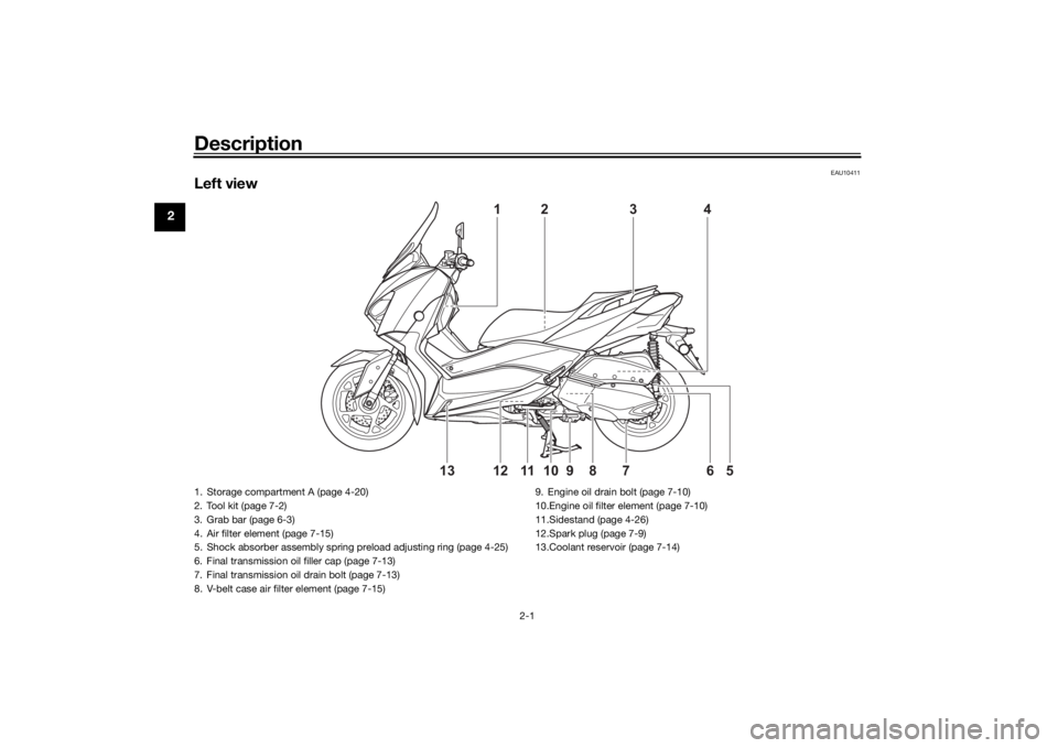
1. Storage compartment A (page 4-20)
2. Tool kit (page 7-2)
3. Grab bar (page 6-3)
4. Air filter element (page 7-15)
5. Shock absorber assembly spring preload adjusting ring (page 4-25)
6. Final transmission oil filler cap (page 7-13)
7. Final transmission oil drain bolt (page 7-13)
8. V-belt case air filter element (page 7-15)9. Engine oil drain bolt (page 7-10)
10.Engine oil filter element (page 7-10)
11.Sidestand (page 4-26)
12.Spark plug (page 7-9)
13.Coolant reservoir (page 7-14)UBBAE1E0.book Page 1 Monday, October 4, 2021 4:51 PM
Page 66 of 116
Periodic maintenance an d a djustment
7-1
7
EAUS1824
Periodic inspection, adjustment, and
lubrication will keep your vehicle in the
safest and most efficient condition
possible. Safety is an obligation of the
vehicle owner/operator. The most im-
portant points of vehicle inspection,
adjustment, and lubrication are ex-
plained on the following pages.
The intervals given in the periodic
maintenance charts should be simply
considered as a general guide under
normal riding conditions. However, de-
pending on the weather, terrain, geo-
graphical location, and individual use,
the maintenance intervals may need to
be shortened.
WARNING
EWA10322
Failure to properly maintain the vehi-
cle or performin g maintenance ac-
tivities incorrectly may increase
your risk of injury or death durin g
service or while usin g the vehicle. If
you are not familiar with vehicle ser-
vice, have a Yamaha d ealer perform
service.
WARNING
EWA15123
Turn off the en gine when performin g
maintenance unless otherwise
specified .
A runnin g en gine has movin g
parts that can catch on body
parts or clothin g an d electrical
parts that can cause shocks or
fires.
Runnin g the en gine while ser-
vicin g can lead to eye injury,
b urns, fire, or car bon monoxi de
poisonin g – possi bly lea din g to
d eath. See pag e 1-3 for more in-
formation a bout car bon monox-
i d e.
WARNING
EWA10331
This scooter is desi gne d for use on
pave d roa ds only. If this scooter is
operated in abnormally dusty, mu d-
d y or wet con ditions, the air filter el-
ement shoul d be cleaned or
replaced more frequently, otherwise
rapi d en gine wear may result. Con-
sult a Yamaha dealer for proper
maintenance intervals.
WARNING
EWA15461
Brake discs, calipers, d rums, and
linin gs can b ecome very hot d uring
use. To avoi d possi ble burns, let
b rake components cool before
touching them.
UBBAE1E0.book Page 1 Monday, October 4, 2021 4:51 PM
Page 69 of 116

Periodic maintenance an d a djustment
7-4
7
EAU71353
General maintenance an d lu brication chartNO. ITEM CHECK OR MAINTENANCE JOB ODOMETER READING
ANNUAL
CHECK
1000 km
(600 mi) 10000 km
(6000 mi) 20000 km
(12000 mi) 30000 km
(18000 mi) 40000 km
(24000 mi)
1 *Dia
gnostic system
check • Perform dynamic inspection us-
ing Yamaha diagnostic tool.
• Check the error codes. √√√√√√
2 *Air filter element •Replace. √√
3 *Pre air filter element • Clean. √√
4 *Su
b air filter ele-
ment •Replace.
√√
5 Air filter case check
hose
• Clean.
√√√√√
6 *V-
belt case air filter
element • Clean.
• Replace if necessary.
√√√√√
7 *Front brake • Check operation, fluid level, and
for fluid leakage.
• Replace brake pads if necessary. √√√√√√
8 *Rear brake • Check operation, fluid level, and
for fluid leakage.
• Replace brake pads if necessary. √√√√√√
9 *Brake hoses • Check for cracks or damage.
√√√√√
• Replace. Every 4 years
10 *Brake flui d • Change. Every 2 years
11 *Wheels • Check runout and for damage.
• Replace if necessary. √√√√
UBBAE1E0.book Page 4 Monday, October 4, 2021 4:51 PM
Page 72 of 116
Periodic maintenance an d a djustment
7-7
7
EAU79370
TIP Engine air filter and V-belt air filter
• This model’s engine air filter is equipped with a disposable oil-coated paper element, which must not be cleaned with compressed air to avoid damaging it.
• The engine air filter element and sub air filter element need to be replaced and the V-belt air filter element needs to be serviced more frequently when riding in unusually wet or dusty areas.
Hydraulic brake service
• After disassembling the brake master cylinders and calipers, always change the fluid. Regularly check the brake fluid levels and fill the reservoirs as required.
• Every two years replace the internal components of the brake master cylinders and calipers, and change the brake fluid.
• Replace the brake hoses every four years and if cracked or damaged.
UBBAE1E0.book Page 7 Monday, October 4, 2021 4:51 PM
Page 80 of 116
Periodic maintenance an d a djustment
7-15
7 5. Remove the coolant reservoir cap,
add coolant to the maximum level
mark, and then install the reservoir
cap. WARNING! Remove only
the coolant reservoir cap. Never
attempt to remove the ra diator
cap when the en gine is hot.
[EWA15162]
NOTICE: If coolant is not
availa ble, use distille d water or
soft tap water instea d. Do not
use har d water or salt water
since it is harmful to the en gine.
If water has been used instead
of coolant, replace it with cool-
ant as soon as possi ble, other-
wise the coolin g system will not
b e protecte d a gainst frost an d
corrosion. If water has been
a dde d to the coolant, have a
Yamaha dealer check the anti-
freeze content of the coolant as
soon as possi ble, otherwise the
effectiveness of the coolant will
b e re duce d.
[ECA10473]
6. Install the coolant reservoir cover.
7. Place the left floorboard mat in the
original position and push it down-
ward to secure it.
EAU33032
Chan gin g the coolant
The coolant must be changed at the in-
tervals specified in the periodic main-
tenance and lubrication chart. Have a
Yamaha dealer change the coolant.
WARNING! Never attempt to remove the ra diator cap when the en gine is
hot.
[EWA10382] EAU78574
Air filter an
d V- belt case air fil-
ter elementsThe air filter element and the sub air fil-
ter element should be replaced, and
the pre air filter element and the V-belt
case air filter element should be
cleaned at the intervals specified in the
periodic maintenance and lubrication
chart. Service the air filter elements
more frequently if you are riding in un-
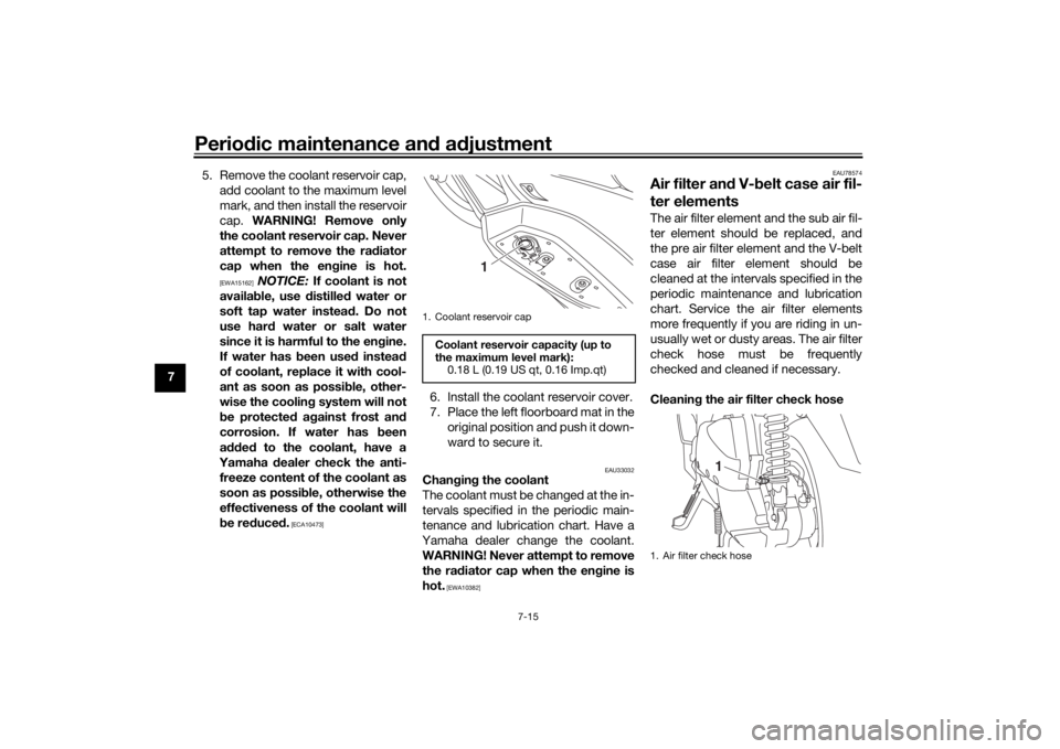
usually wet or dusty areas. The air filter
check hose must be frequently
checked and cleaned if necessary.
Cleanin g the air filter check hose
1. Coolant reservoir capCoolant reservoir capacity (up to
the maximum level mark):
0.18 L (0.19 US qt, 0.16 Imp.qt)
1
1. Air filter check hose
1
UBBAE1E0.book Page 15 Monday, October 4, 2021 4:51 PM
Page 81 of 116
Periodic maintenance an d a djustment
7-16
7
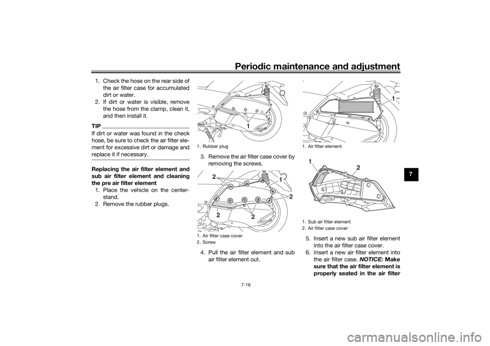
1. Check the hose on the rear side of
the air filter case for accumulated
dirt or water.
2. If dirt or water is visible, remove the hose from the clamp, clean it,
and then install it.
TIPIf dirt or water was found in the check
hose, be sure to check the air filter ele-
ment for excessive dirt or damage and
replace it if necessary.Replacin g the air filter element an d
su b air filter element an d cleanin g
the pre air filter element 1. Place the vehicle on the center- stand.
2. Remove the rubber plugs. 3. Remove the air filter case cover by
removing the screws.
4. Pull the air filter element and sub air filter element out. 5. Insert a new sub air filter element
into the air filter case cover.
6. Insert a new air filter element into the air filter case. NOTICE: Make
sure that the air filter element is
properly seated in the air filter
1. Rubber plug
1. Air filter case cover
2. Screw
1
1
2
2
2
2
1. Air filter element
1. Sub air filter element
2. Air filter case cover
1
1
2
UBBAE1E0.book Page 16 Monday, October 4, 2021 4:51 PM
Page 82 of 116
Periodic maintenance an d a djustment
7-17
7 case. The en
gine shoul d never
b e operated without the air filter
element installe d, otherwise the
piston(s) an d/or cylin der(s) may
b ecome excessively worn.
[ECA10482]
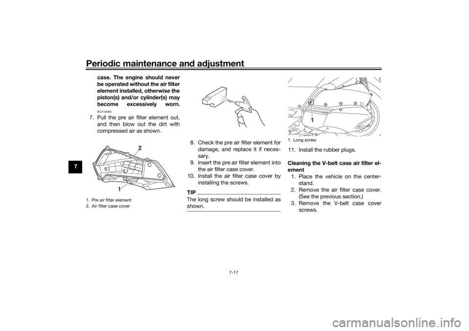
7. Pull the pre air filter element out,
and then blow out the dirt with
compressed air as shown.
8. Check the pre air filter element fordamage, and replace it if neces-
sary.
9. Insert the pre air filter element into the air filter case cover.
10. Install the air filter case cover by installing the screws.
TIPThe long screw should be installed as
shown.
11. Install the rubber plugs.
Cleanin g the V- belt case air filter el-
ement 1. Place the vehicle on the center- stand.
2. Remove the air filter case cover. (See the previous section.)
3. Remove the V-belt case cover screws.
1. Pre air filter element
2. Air filter case cover
1
2
1. Long screw
1
UBBAE1E0.book Page 17 Monday, October 4, 2021 4:51 PM
Page 83 of 116
Periodic maintenance an d a djustment
7-18
7
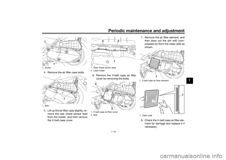
4. Remove the air filter case bolts.
5. Lift up the air filter case slightly, re-
move the rear wheel sensor lead
from the holder, and then remove
the V-belt case cover. 6. Remove the V-belt case air filter
cover by removing the bolts. 7. Remove the air filter element, and
then blow out the dirt with com-
pressed air from the clean side as
shown.
8. Check the V-belt case air filter ele- ment for damage and replace it if
necessary.
1. Screw
1. Bolt
1
1
1
1. Rear wheel sensor lead
2. Lead holder
1. V-belt case air filter cover
2. Bolt
1
2
2
1
2
2
1. V-belt case air filter element
1. Clean side
1
1
UBBAE1E0.book Page 18 Monday, October 4, 2021 4:51 PM
Page 84 of 116
Periodic maintenance an d a djustment
7-19
7 9. Insert the element into the V-belt
case.
10. Install the V-belt case air filter cov- er by installing the bolts.
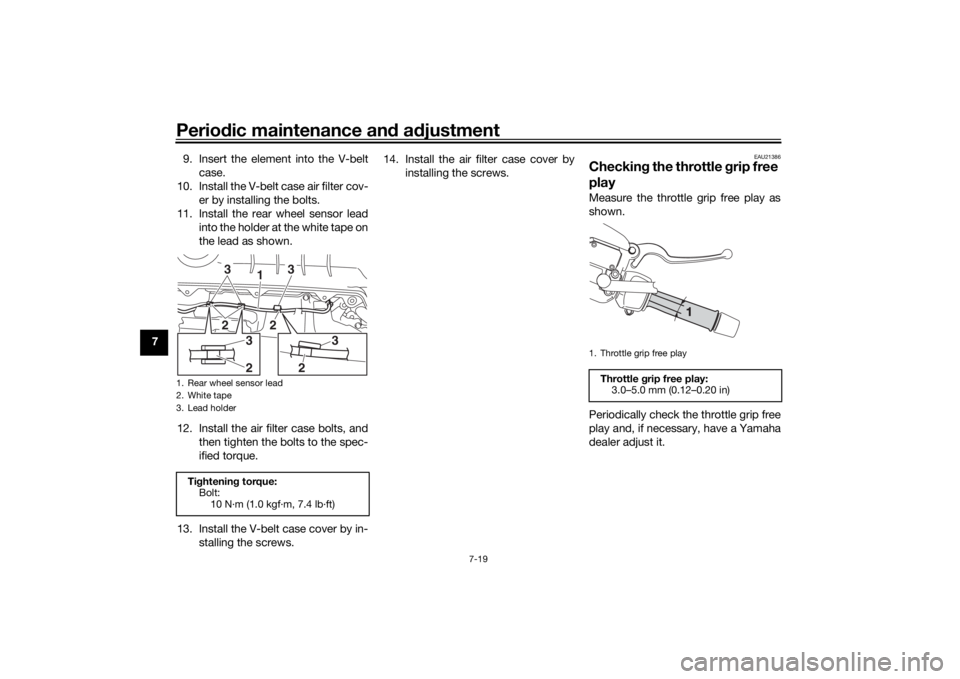
11. Install the rear wheel sensor lead into the holder at the white tape on
the lead as shown.
12. Install the air filter case bolts, and then tighten the bolts to the spec-
ified torque.
13. Install the V-belt case cover by in- stalling the screws. 14. Install the air filter case cover by
installing the screws.
EAU21386
Checkin g the throttle grip free
playMeasure the throttle grip free play as
shown.
Periodically check the throttle grip free
play and, if necessary, have a Yamaha
dealer adjust it.
1. Rear wheel sensor lead
2. White tape
3. Lead holderTi ghtenin g torque:
Bolt:
10 N·m (1.0 kgf·m, 7.4 lb·ft)
13
3
2
2
3
2
2
3
1. Throttle grip free playThrottle grip free play:
3.0–5.0 mm (0.12–0.20 in)
UBBAE1E0.book Page 19 Monday, October 4, 2021 4:51 PM