belt YAMAHA XMAX 300 2022 Owners Manual
[x] Cancel search | Manufacturer: YAMAHA, Model Year: 2022, Model line: XMAX 300, Model: YAMAHA XMAX 300 2022Pages: 116, PDF Size: 4.64 MB
Page 8 of 116

Table of contentsSafety information ............................ 1-1
Further safe-riding points ............... 1-5
Description ....................................... 2-1
Left view ......................................... 2-1
Right view ....................................... 2-2
Controls and instruments ............... 2-3
Smart key system ........................... 3-1
Smart key system ........................... 3-1
Operating range of the smart key system......................................... 3-2
Handling of the smart key and mechanical keys ......................... 3-3
Smart key ....................................... 3-5
Replacing the smart key battery..... 3-6
Main switch .................................... 3-8
Instrument an d control functions ... 4-1
Indicator lights and warning
lights............................................ 4-1
Speedometer .................................. 4-3
Tachometer .................................... 4-3
Multi-function display ..................... 4-4
Handlebar switches ...................... 4-12
Front brake lever .......................... 4-13
Rear brake lever ........................... 4-14
Anti-lock brake system (ABS)....... 4-14
Traction control system ................ 4-15
Fuel tank cap ................................ 4-17
Fuel ............................................... 4-18 Fuel tank overflow hose ................ 4-19
Catalytic converter ........................ 4-20
Storage compartments ................. 4-20
Windshield .................................... 4-22
Handlebar position ....................... 4-24
Adjusting the shock absorber
assemblies ................................. 4-25
Auxiliary DC jack .......................... 4-25
Sidestand ...................................... 4-26
Ignition circuit cut-off system ....... 4-27
For your safety – pre-operation
checks ............................................... 5-1
Operation an d important ri din g
points ................................................. 6-1
Engine break-in ............................... 6-1
Starting the engine .......................... 6-2
Starting off ...................................... 6-3
Acceleration and deceleration ........ 6-3
Braking ............................................ 6-3
Tips for reducing fuel consumption ................................ 6-4
Parking ............................................ 6-4
Perio dic maintenance an d
a d justment ........................................ 7-1
Tool kit ............................................ 7-2
Periodic maintenance charts .......... 7-3
Periodic maintenance chart for the emission control system .............. 7-3 General maintenance and
lubrication chart .......................... 7-4
Removing and installing the panel............................................ 7-8
Checking the spark plug................. 7-9
Canister ........................................ 7-10
Engine oil and oil filter element..... 7-10
Final transmission oil .................... 7-13
Coolant ......................................... 7-14
Air filter and V-belt case air filter elements .................................... 7-15
Checking the throttle grip free play ............................................ 7-19
Valve clearance............................. 7-20
Tires .............................................. 7-20
Cast wheels .................................. 7-22
Checking the front and rear
brake lever free play .................. 7-22
Checking the front and rear brake pads ................................ 7-23
Checking the brake fluid level ...... 7-23
Changing the brake fluid .............. 7-25
Checking the V-belt ...................... 7-25
Checking and lubricating the cables ........................................ 7-25
Checking and lubricating the
throttle grip and cable ............... 7-26
Lubricating the front and rear brake levers ............................... 7-26
Checking and lubricating the centerstand and sidestand........ 7-27UBBAE1E0.book Page 1 Monday, October 4, 2021 4:51 PM
Page 16 of 116
Description
2-1
2
EAU10411
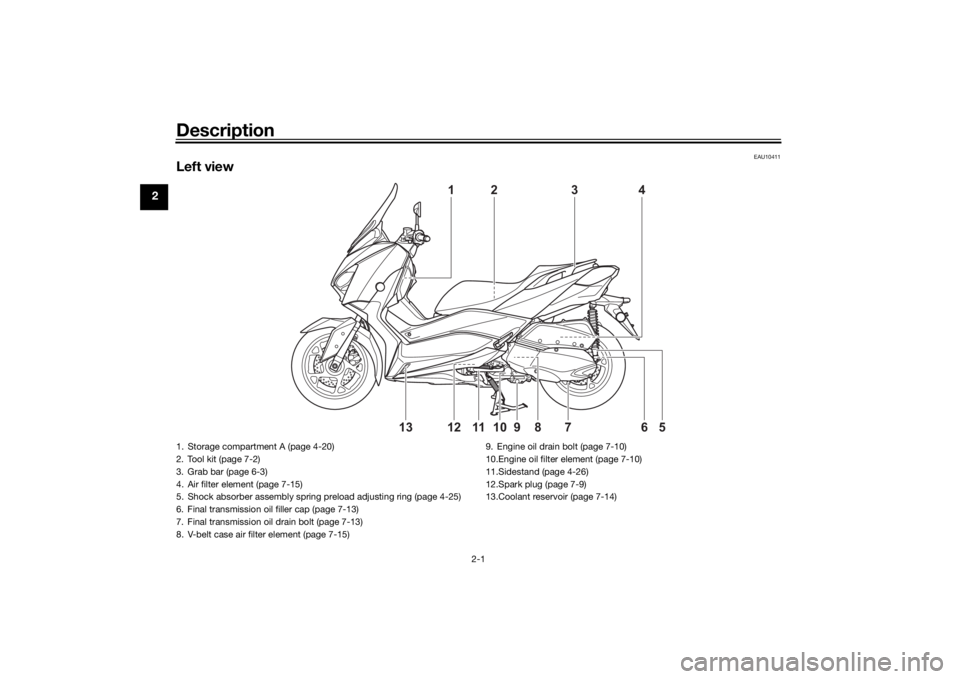
Left view
4
1
5
6
10
8
12
7
9
11
13
2
3
1. Storage compartment A (page 4-20)
2. Tool kit (page 7-2)
3. Grab bar (page 6-3)
4. Air filter element (page 7-15)
5. Shock absorber assembly spring preload adjusting ring (page 4-25)
6. Final transmission oil filler cap (page 7-13)
7. Final transmission oil drain bolt (page 7-13)
8. V-belt case air filter element (page 7-15)9. Engine oil drain bolt (page 7-10)
10.Engine oil filter element (page 7-10)
11.Sidestand (page 4-26)
12.Spark plug (page 7-9)
13.Coolant reservoir (page 7-14)UBBAE1E0.book Page 1 Monday, October 4, 2021 4:51 PM
Page 31 of 116
Instrument and control functions
4-1
4
EAU4939R
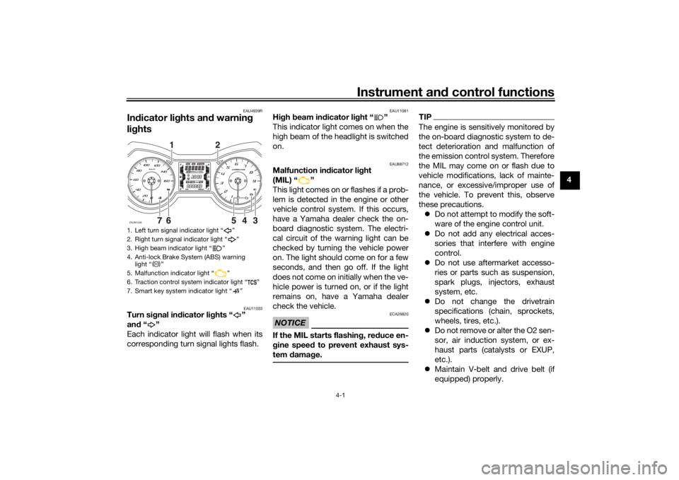
In dicator lig hts and warning
lig hts
EAU11033
Turn si gnal in dicator li ghts “ ”
an d“”
Each indicator light will flash when its
corresponding turn signal lights flash.
EAU11081
Hi gh beam in dicator li ght “ ”
This indicator light comes on when the
high beam of the headlight is switched
on.
EAU88712
Malfunction in dicator li ght
(MIL) “ ”
This light comes on or flashes if a prob-
lem is detected in the engine or other
vehicle control system. If this occurs,
have a Yamaha dealer check the on-
board diagnostic system. The electri-
cal circuit of the warning light can be
checked by turning the vehicle power
on. The light should come on for a few
seconds, and then go off. If the light
does not come on initially when the ve-
hicle power is turned on, or if the light
remains on, have a Yamaha dealer
check the vehicle.NOTICE
ECA26820
If the MIL starts flashin g, re duce en-
g ine spee d to prevent exhaust sys-
tem damag e.
TIPThe engine is sensitively monitored by
the on-board diagnostic system to de-
tect deterioration and malfunction of
the emission control system. Therefore
the MIL may come on or flash due to
vehicle modifications, lack of mainte-
nance, or excessive/improper use of
the vehicle. To prevent this, observe
these precautions.
Do not attempt to modify the soft-
ware of the engine control unit.
Do not add any electrical acces-
sories that interfere with engine
control.
Do not use aftermarket accesso-
ries or parts such as suspension,
spark plugs, injectors, exhaust
system, etc.
Do not change the drivetrain
specifications (chain, sprockets,
wheels, tires, etc.).
Do not remove or alter the O2 sen-
sor, air induction system, or ex-
haust parts (catalysts or EXUP,
etc.).
Maintain V-belt and drive belt (if
equipped) properly.
1. Left turn signal indicator light “ ”
2. Right turn signal indicator light “ ”
3. High beam indicator light “ ”
4. Anti-lock Brake System (ABS) warning
light “ ”
5. Malfunction indicator light “ ”
6. Traction control system indicator light “ ”
7. Smart key system indicator light “ ”ZAUM1548
1
2
ABS
UBBAE1E0.book Page 1 Monday, October 4, 2021 4:51 PM
Page 36 of 116
Instrument and control functions
4-6
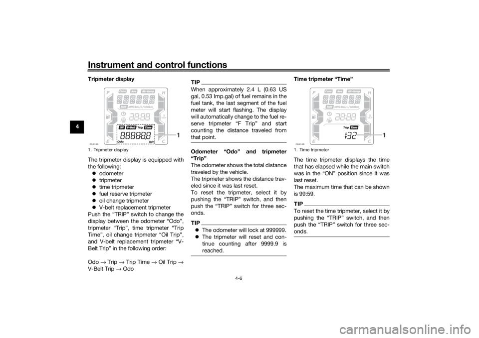
4 Tripmeter
display
The tripmeter display is equipped with
the following: odometer
tripmeter
time tripmeter
fuel reserve tripmeter
oil change tripmeter
V-belt replacement tripmeter
Push the “TRIP” switch to change the
display between the odometer “Odo”,
tripmeter “Trip”, time tripmeter “Trip
Time”, oil change tripmeter “Oil Trip”,
and V-belt replacement tripmeter “V-
Belt Trip” in the following order:
Odo → Trip → Trip Time → Oil Trip →
V-Belt Trip → Odo
TIPWhen approximately 2.4 L (0.63 US
gal, 0.53 Imp.gal) of fuel remains in the
fuel tank, the last segment of the fuel
meter will start flashing. The display
will automatically change to the fuel re-
serve tripmeter “F Trip” and start
counting the distance traveled from
that point.Odometer “O do” an d tripmeter
“Trip”
The odometer shows the total distance
traveled by the vehicle.
The tripmeter shows the distance trav-
eled since it was last reset.
To reset the tripmeter, select it by
pushing the “TRIP” switch, and then
push the “TRIP” switch for three sec-
onds.TIP The odometer will lock at 999999.
The tripmeter will reset and con-
tinue counting after 9999.9 is
reached.
Time tripmeter “Time”
The time tripmeter displays the time
that has elapsed while the main switch
was in the “ON” position since it was
last reset.
The maximum time that can be shown
is 99:59.TIPTo reset the time tripmeter, select it by
pushing the “TRIP” switch, and then
push the “TRIP” switch for three sec-
onds.
1. Tripmeter displayZAUM1485
1
1. Time tripmeterZAUM1486
1
UBBAE1E0.book Page 6 Monday, October 4, 2021 4:51 PM
Page 37 of 116
Instrument and control functions
4-7
4
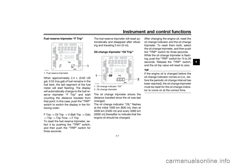
Fuel reserve tripmeter “F Trip”
When approximately 2.4 L (0.63 US
gal, 0.53 Imp.gal) of fuel remains in the
fuel tank, the last segment of the fuel
meter will start flashing. The display
will automatically change to the fuel re-
serve tripmeter “F Trip” and start
counting the distance traveled from
that point. In this case, push the “TRIP”
switch to switch the display in the fol-
lowing order:
F Trip
→ Oil Trip → V-Belt Trip → Odo
→ Trip → Trip Time → F Trip
To reset the fuel reserve tripmeter, se-
lect it by pushing the “TRIP” switch,
and then push the “TRIP” switch for
three seconds. The fuel reserve tripmeter will reset au-
tomatically and disappear after refuel-
ing and traveling 5 km (3 mi).
Oil chan
ge tripmeter “Oil Trip”
The oil change tripmeter shows the
distance traveled since the oil was last
changed.
The oil change indicator “OIL” flashes
at the initial 1000 km (600 mi), then at
4000 km (2400 mi) and every 5000 km
(3000 mi) thereafter to indicate that the
engine oil should be changed. After changing the engine oil, reset the
oil change indicator and the oil change
tripmeter. To reset them both, select
the oil change tripmeter, and then push
the “TRIP” switch for three seconds.
While the oil change tripmeter is flash-
ing, push the “TRIP” switch for 15 to 20
seconds. Release the “TRIP” switch,
and the oil trip value will reset to zero.
TIPIf the engine oil is changed before the
oil change indicator comes on (i.e., be-
fore the periodic oil change interval has
been reached), the oil change tripmeter
must be reset for the oil change indica-
tor to come on at the correct time.
1. Fuel reserve tripmeterZAUM1487
1
1. Oil change indicator “Oil”
2. Oil change tripmeterZAUM14881
2
UBBAE1E0.book Page 7 Monday, October 4, 2021 4:51 PM
Page 38 of 116
Instrument and control functions
4-8
4 V-
belt replacement tripmeter “V-
Belt Trip”
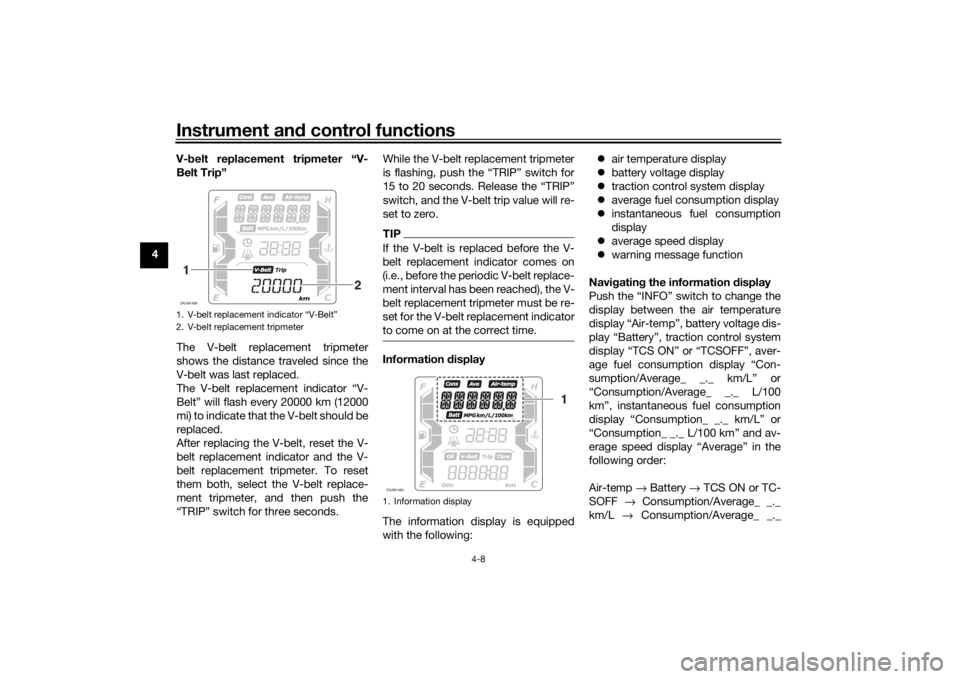
The V-belt replacement tripmeter
shows the distance traveled since the
V-belt was last replaced.
The V-belt replacement indicator “V-
Belt” will flash every 20000 km (12000
mi) to indicate that the V-belt should be
replaced.
After replacing the V-belt, reset the V-
belt replacement indicator and the V-
belt replacement tripmeter. To reset
them both, select the V-belt replace-
ment tripmeter, and then push the
“TRIP” switch for three seconds. While the V-belt replacement tripmeter
is flashing, push the “TRIP” switch for
15 to 20 seconds. Release the “TRIP”
switch, and the V-belt trip value will re-
set to zero.
TIPIf the V-belt is replaced before the V-
belt replacement indicator comes on
(i.e., before the periodic V-belt replace-
ment interval has been reached), the V-
belt replacement tripmeter must be re-
set for the V-belt replacement indicator
to come on at the correct time.Information
display
The information display is equipped
with the following:
air temperature display
battery voltage display
traction control system display
average fuel consumption display
instantaneous fuel consumption
display
average speed display
warning message function
Navi gatin g the information display
Push the “INFO” switch to change the
display between the air temperature
display “Air-temp”, battery voltage dis-
play “Battery”, traction control system
display “TCS ON” or “TCSOFF”, aver-
age fuel consumption display “Con-
sumption/Average_ _._ km/L” or
“Consumption/Average_ _._ L/100
km”, instantaneous fuel consumption
display “Consumption_ _._ km/L” or
“Consumption_ _._ L/100 km” and av-
erage speed display “Average” in the
following order:
Air-temp → Battery → TCS ON or TC-
SOFF → Consumption/Average_ _._
km/L → Consumption/Average_ _._
1. V-belt replacement indicator “V-Belt”
2. V-belt replacement tripmeterZAUM14891
2
1. Information displayZAUM1490
1
UBBAE1E0.book Page 8 Monday, October 4, 2021 4:51 PM
Page 42 of 116
Instrument and control functions
4-12
4 “OIL SERV”: Appears when the oil
change indicator “OIL” starts flashing.
If “OIL SERV” is displayed, change the
engine oil, and then reset the oil
change indicator and oil change trip-
meter.
“V-BELT SERV”: Appears when the V-
belt replacement indicator “V-Belt”
starts flashing. If “V-BELT SERV” is
displayed, replace the V-belt, and then
reset the V-belt replacement indicator
and V-belt replacement tripmeter.
When there are two or more warnings,
the warning messages are displayed in
the following order:
L FUEL →
H TEMP → ICE → OIL SERV
→ VBELT SERV → L FUEL
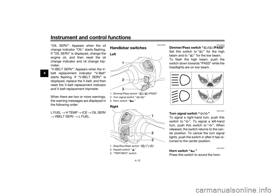
EAU1234R
Han dle bar switchesLeft
Ri ght
EAU54203
Dimmer/Pass switch “ / /PASS”
Set this switch to “ ” for the high
beam and to “ ” for the low beam.
To flash the high beam, push the
switch down towards “PASS” while the
headlights are on low beam.
EAU12461
Turn si gnal switch “ / ”
To signal a right-hand turn, push this
switch to “ ”. To signal a left-hand
turn, push this switch to “ ”. When
released, the switch returns to the cen-
ter position. To cancel the turn signal
lights, push the switch in after it has re-
turned to the center position.
EAU12501
Horn switch “ ”
Press this switch to sound the horn.
1. Dimmer/Pass switch “ / /PASS”
2. Turn signal switch “ / ”
3. Horn switch “ ”
1. Stop/Run/Start switch “ / / ”
2. Hazard switch “ ”
3. “TRIP/INFO” switch
123
123
UBBAE1E0.book Page 12 Monday, October 4, 2021 4:51 PM
Page 69 of 116

Periodic maintenance an d a djustment
7-4
7
EAU71353
General maintenance an d lu brication chartNO. ITEM CHECK OR MAINTENANCE JOB ODOMETER READING
ANNUAL
CHECK
1000 km
(600 mi) 10000 km
(6000 mi) 20000 km
(12000 mi) 30000 km
(18000 mi) 40000 km
(24000 mi)
1 *Dia
gnostic system
check • Perform dynamic inspection us-
ing Yamaha diagnostic tool.
• Check the error codes. √√√√√√
2 *Air filter element •Replace. √√
3 *Pre air filter element • Clean. √√
4 *Su
b air filter ele-
ment •Replace.
√√
5 Air filter case check
hose
• Clean.
√√√√√
6 *V-
belt case air filter
element • Clean.
• Replace if necessary.
√√√√√
7 *Front brake • Check operation, fluid level, and
for fluid leakage.
• Replace brake pads if necessary. √√√√√√
8 *Rear brake • Check operation, fluid level, and
for fluid leakage.
• Replace brake pads if necessary. √√√√√√
9 *Brake hoses • Check for cracks or damage.
√√√√√
• Replace. Every 4 years
10 *Brake flui d • Change. Every 2 years
11 *Wheels • Check runout and for damage.
• Replace if necessary. √√√√
UBBAE1E0.book Page 4 Monday, October 4, 2021 4:51 PM
Page 71 of 116

Periodic maintenance an d a djustment
7-6
7
21 En gine oil • Change (warm engine before
draining).
• Check oil level and vehicle for oil leakage. At the initial interval and when the oil change indicator flashes or
comes on. √
22 En
gine oil filter ele-
ment •Replace.
√√√
23 *Final transmission
oil • Check vehicle for oil leakage.
√√√√√
• Change. √√√
24 *Coolin g system • Check coolant level and vehicle
for coolant leakage. √√√√√
• Change. Every 3 years
25 *V-belt • Replace. When the V-belt replacement indicator flashes [every 20000 km (12000 mi)]
26 *Front an
d rear
b rake switches • Check operation.
√√√√√√
27 *Movin
g parts an d
ca bles • Lubricate.
√√√√√
28 *Throttle g
rip hous-
in g an d ca ble • Check operation and free play.
• Adjust the throttle cable free play
if necessary.
• Lubricate the throttle grip housing and cable. √√√√√
29 *Li
ghts, si gnals an d
switches • Check operation.
• Adjust headlight beam.
√√√√√√
NO. ITEM CHECK OR MAINTENANCE JOB
ODOMETER READING
ANNUAL
CHECK
1000 km
(600 mi) 10000 km
(6000 mi) 20000 km
(12000 mi) 30000 km
(
18000 mi)40000 km
(24000 mi)
UBBAE1E0.book Page 6 Monday, October 4, 2021 4:51 PM
Page 72 of 116
Periodic maintenance an d a djustment
7-7
7
EAU79370
TIP Engine air filter and V-belt air filter
• This model’s engine air filter is equipped with a disposable oil-coated paper element, which must not be cleaned with compressed air to avoid damaging it.
• The engine air filter element and sub air filter element need to be replaced and the V-belt air filter element needs to be serviced more frequently when riding in unusually wet or dusty areas.
Hydraulic brake service
• After disassembling the brake master cylinders and calipers, always change the fluid. Regularly check the brake fluid levels and fill the reservoirs as required.
• Every two years replace the internal components of the brake master cylinders and calipers, and change the brake fluid.
• Replace the brake hoses every four years and if cracked or damaged.
UBBAE1E0.book Page 7 Monday, October 4, 2021 4:51 PM