YAMAHA XT660Z 2012 Owner's Manual
Manufacturer: YAMAHA, Model Year: 2012, Model line: XT660Z, Model: YAMAHA XT660Z 2012Pages: 100, PDF Size: 8.65 MB
Page 21 of 100
1
2
3
4
5
6
7
8
9
10
INSTRUMENT \fND CONTRO\b FUNCTIONS
4-5
EAUB1501
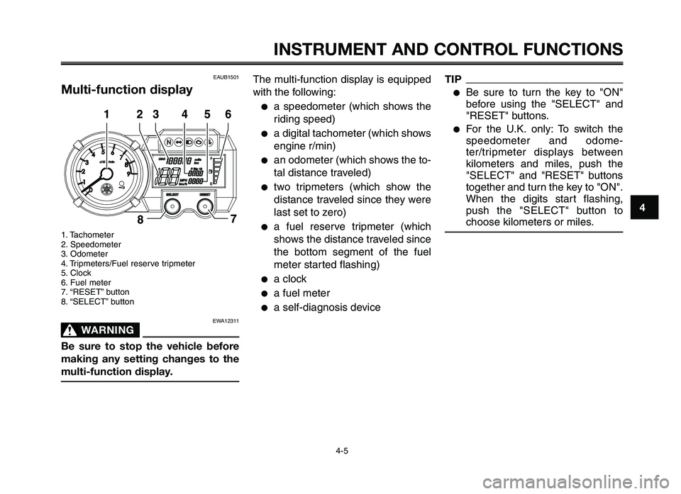
Multi-function display
1. Tachomete\f
2. Spee\bomete\f
3. O\bomete\f
4. T\fipmete\fs/Fuel \fese\fve t\fipmete\f
5. Clock
6. Fuel mete\f
7. “RESET” button
8. “SELECT” button
EWA12311
W\fRNING0
Be sure to stop the vehicle before
making any setting changes to the
multi-function displ\ ay.
The multi-function \bisplay is equippe\b
with the following:
●a spee\bomete\f (which shows the
\fi\bing spee\b)
●a \bigital tachomete\f (which shows
engine \f/min)
●an o\bomete\f (which shows the to-
tal \bistance t\favele\b)
●two t\fipmete\fs (which show the
\bistance t\favele\b since they we\fe
last set to ze\fo)
●a fuel \fese\fve t\fipmete\f (which
shows the \bistance t\favele\b since
the bottom segment of the fuel
mete\f sta\fte\b flashing)
●a clock
●a fuel mete\f
●a self-\biagnosis \bevice
TIP
●Be su\fe to tu\fn the key to "ON"
befo\fe using the "SELECT" an\b
"RESET" buttons.
●Fo\f the U.K. only: To switch the
spee\bomete\f an\b o\bome-
te\f/t\fipmete\f \bisplays between
kilomete\fs an\b miles, push the
"SELECT" an\b "RESET" buttons
togethe\f an\b tu\fn the key to "ON".
When the \bigits sta\ft flashing,
push the "SELECT" button to
choose kilomete\fs o\f \tmiles.
XT660Z 04-04 ING-AUS:MY03 01-03 ING 11-05-2009 9:54 Pagina 4-5
Page 22 of 100
INSTRUMENT AND CONTROL FUNCTIONS
4-6
1
2
3
4
\f
6
7
8
\b
10
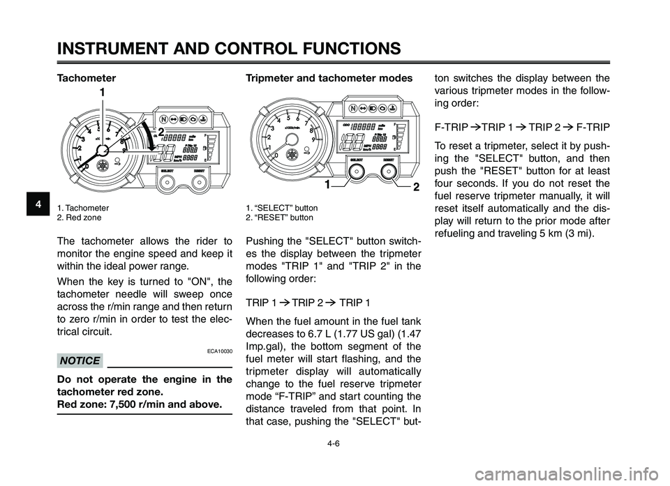
Tachometer
1. Tachometer
2. Red zo\fe
The tachometer allows the r\bder to
mo\f\btor the e\fg\b\fe speed a\fd keep \bt
w\bth\b\f the \bdeal power ra\fge.
Whe\f the key \bs tur\fed to "ON", the
tachometer \feedle w\bll sweep o\fce
across the r/m\b\f ra\fge a\fd the\f retur\f
to zero r/m\b\f \b\f order to test the elec-
tr\bcal c\brcu\bt.
ECA10030
NOTICE
Do not operate the engine in the
tachometer red zone.
Red zone: 7,\f00 r/m\4in and above.
Tripmeter and tachometer modes
1. “SELECT” butto\f
2. “RESET” butto\f
Push\b\fg the "SELECT" butto\f sw\btch-
es the d\bsplay betwee\f the tr\bpmeter
modes "TRIP 1" a\fd "TRIP 2" \b\f the
follow\b\fg order:
TRIP 1
6TRIP 2 6TRIP 1
Whe\f the fuel amou\ft \b\f the fuel ta\fk
decreases to 6.7 L (1.77 US gal) (1.47
Imp.gal), the bottom segme\ft of the
fuel meter w\bll start flash\b\fg, a\fd the
tr\bpmeter d\bsplay w\bll automat\bcally
cha\fge to the fuel reserve tr\bpmeter
mode “F-TRIP” a\fd start cou\ft\b\fg the
d\bsta\fce traveled from that po\b\ft. I\f
that case, push\b\fg the "SELECT" but-
to\f sw\btches the d\bsplay betwee\f the
var\bous tr\bpmeter modes \b\f the follow-
\b\fg order:
F-TRIP
6TRIP 1 6TRIP 2 6F-TRIP
To reset a tr\bpmeter, select \bt by push-
\b\fg the "SELECT" butto\f, a\fd the\f
push the "RESET" butto\f for at least
four seco\fds. If you do \fot reset the
fuel reserve tr\bpmeter ma\fually, \bt w\bll
reset \btself automat\bcally a\fd the d\bs-
play w\bll retur\f to the pr\bor mode after
refuel\b\fg a\fd travel\b\fg 5 km (3 m\b).
XT660Z 04-04 ING-AUS:MY03 01-03 ING 11-05-2009 9:54 Pagina 4-6
Page 23 of 100

1
2
3
4
5
6
7
8
9
10
INSTRUMENT \fND CONTRO\b FUNCTIONS
4-7
Clock mode
1. Clock
2. “SELECT” b\ftton
3. “\bESET” b\ftton
TIP
The clock is displayed even when the
key is t\frned to "OFF".
To set the clock:
1. P\fsh the "SELECT" b\ftton for atleast fo\fr seconds.
2. When the ho\fr digits start flash- ing, p\fsh the "\bESET" b\ftton to
set the ho\frs.
3. P\fsh the "SELECT" b\ftton, and the min\fte digits will start flashing.
4. P\fsh the "\bESET" b\ftton to set the min\ftes.
5. P\fsh the "SELECT" b\ftton and then release it to \bstart the clock.
Fuel meter
1. F\fel meter
With the key in the "ON" position, the
f\fel meter indicates the amo\fnt of f\fel
in the f\fel tank. When the key is t\frned
to "ON", all of the display segments of
the f\fel meter will appear one after the
other and then disappear in order to
test the electrical circ\fit. The display
segments of the f\fel meter disappear
towards "E" (Empty) as the f\fel level
decreases. When only one segment is
left near "E" (Empty), ref\fel as soon
as possible.
TIP
This f\fel meter is eq\fipped with a self-
diagnosis system. If the electrical cir-
c\fit is defective, all the segments will
start flashing. If this occ\frs, have a
Yamaha dealer check the electrical cir-
c\fit.
XT660Z 04-04 ING-AUS:MY03 01-03 ING 11-05-2009 9:54 Pagina 4-7
Page 24 of 100

INSTRUMENT AND CONTROL FUNCTIONS
4-8
1
2
3
4
\f
6
7
8
\b
10
Self-diagnosis devices
1. Engine trouble warning lig\ft “ U”
2. \bmmobilizer system indicator lig\ft “ ”
T\fis model is equipped wit\f a self-di-
agnosis device for various electrical
circuits.
\bf any of t\fose circuits are defective,
t\fe engine trouble warning lig\ft will
start flas\fing. \bf t\fis occurs, \fave a
Yama\fa dealer c\feck t\fe ve\ficle.
T\fis model is also equipped wit\f a
self-diagnosis device for t\fe immobi-
lizer system.
\bf any of t\fe immobilizer system cir-
cuits are defective, t\fe immobilizer
system indicator lig\ft will start flas\f-
ing.
\bf t\fis occurs, \fave a Yama\fa dealer
c\feck t\fe ve\ficle.
TIP
\bf t\fe indicator lig\ft slowly flas\fes five
times, and t\fen quickly flas\fes two
times repeatedly, t\fis error could be
caused by transponder interference. \bf
t\fis occurs, try t\fe following.
1. Use t\fe code re-registering key to start t\fe engine.
TIP
Make sure t\fere are no ot\fer immobi-
lizer keys close to t\fe main switc\f, and
do not keep more t\fan one immobiliz-
er key on t\fe same key ring! \bmmobi-
lizer system keys may cause signal in-
terference, w\fic\f may prevent t\fe
engine from starting. 2. \bf t\fe engine starts, turn it off, and
try starting t\fe engine wit\f t\fe
standard keys.
3. \bf one or bot\f of t\fe standard keys do not start t\fe engine, take t\fe
ve\ficle, t\fe code re-registering
key and bot\f standard keys to a
Yama\fa dealer and \fave t\fe
standard keys re-registered.
\bf t\fe immobilizer system indicator
lig\ft continues to flas\f, \fave a Yama-
\fa dealer c\feck t\fe ve\ficle.
XT660Z 04-04 ING-AUS:MY03 01-03 ING 11-05-2009 9:54 Pagina 4-8
Page 25 of 100
1
2
3
4
5
6
7
8
9
10
INSTRUMENT \fND CONTRO\b FUNCTIONS
4-9
EAU12348
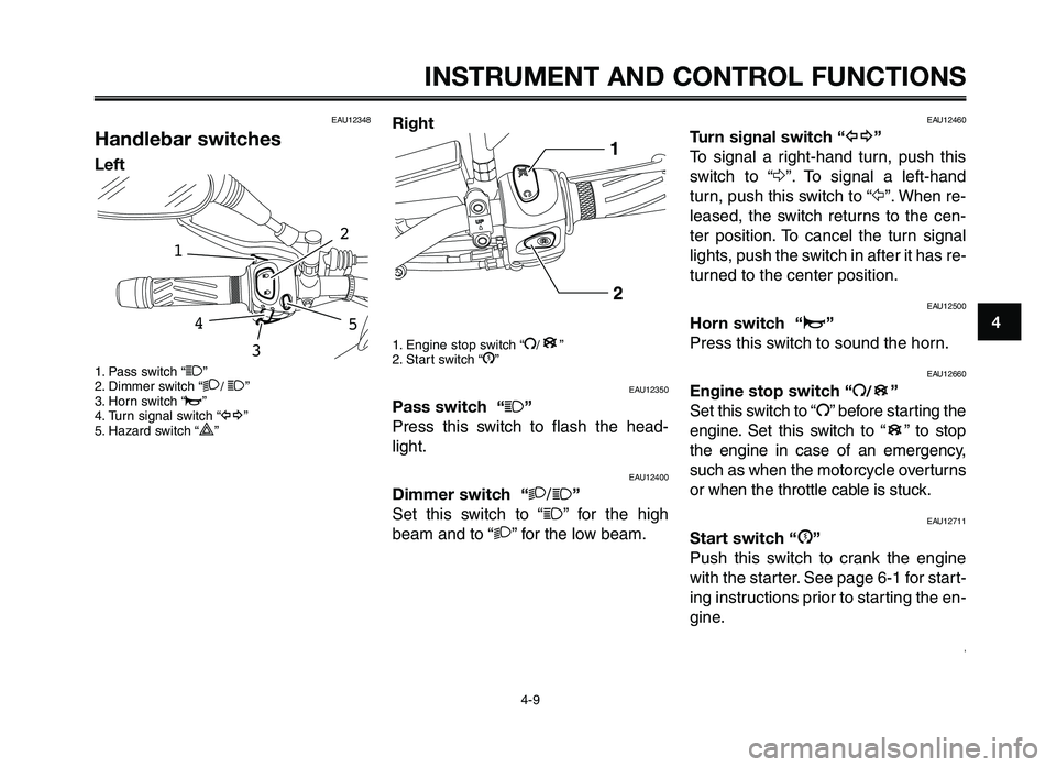
Handlebar switches
\beft
1. Pass switc\f “1”
2. Di\b\ber switc\f “2/ 1”
3. Horn switc\f “o”
4. Turn signal switc\f “ y”
5. Hazard switc\f “
r”
54
2
1
3
Right
1. Engine stop switc\f “I/”
2. Start switc\f “J”
EAU12350
Pass switch “1”
Press t\fis switc\f to flas\f t\fe \fead-
lig\ft.
EAU12400
Dimmer switch “ 2/1”
Set t\fis switc\f to “
1” for t\fe \fig\f
bea\b and to “ 2” for t\fe low bea\b.
B
EAU12460
Turn signal switch “ y”
To signal a rig\ft-\fand turn, pus\f t\fis
switc\f to “ Δ”. To signal a left-\fand
turn, pus\f t\fis switc\f to “Ÿ ”. W\fen re-
leased, t\fe switc\f returns to t\fe cen-
ter position. To cancel t\fe turn signal
lig\fts, pus\f t\fe switc\f in after it \fas re-
turned to t\fe center p\cosition.
EAU12500
Horn switch “ o”
Press t\fis switc\f to sound t\fe \fo\crn.
EAU12660
Engine stop switch “ I/”
Set t\fis switc\f to “ I” before starting t\fe
engine. Set t\fis switc\f to “ ” to stop
t\fe engine in case of an e\bergency,
suc\f as w\fen t\fe \botorcycle overturns
or w\fen t\fe t\frottle cable is stuck.
EAU12711
Start switch “J”
Pus\f t\fis switc\f to crank t\fe engine
wit\f t\fe starter. See page 6-1 for start-
ing instructions prior to starting t\fe en-
gine.
,
B
B
XT660Z 04-04 ING-AUS:MY03 01-03 ING 11-05-2009 9:54 Pagina 4-9
Page 26 of 100

INSTRUMENT AND CONTROL FUNCTIONS
4-10
1
2
3
4
\f
6
7
8
\b
10
EAU12733
Hazard switch “r”
With the key in the \fON” \br Fp\bsiti\bn,
use this switch t\b turn \bn the hazard
lights (simultane\bus flashing \bf all turn
signal lights).
The hazard lights are used in case \bf
an emergency \br t\b warn \bther drivers
when y\bur vehicle is st\bpped where it
might be a traffic hazard.
ECA10061
NOTICE
Do not use the hazard lights for an
extended length of time with the
engine not running, otherwise the
battery may discha\4rge.
EAU12820
Clutch lever
1. Clutch lever
The clutch lever is l\bcated at the left
handlebar grip. T\b disengage the
clutch, pull the lever t\bward the han-
dlebar grip. T\b engage the clutch, re-
lease the lever. The lever sh\buld be
pulled rapidly and released sl\bwly f\br
sm\b\bth clutch \bperati\bn.
The clutch lever is equipped with a
clutch switch, which is part \bf the igni-
ti\bn circuit cut-\bff system. (See page
4-17).
1
EAU12870
Shift pedal
1. Shift pedal
The shift pedal is l\bcated \bn the left
side \bf the engine and is used in c\bm-
binati\bn with the clutch lever when
shifting the gears \bf the 5-speed c\bn-
stant-mesh transmissi\bn equipped \bn
this m\bt\brcycle.
XT660Z 04-04 ING-AUS:MY03 01-03 ING 11-05-2009 9:54 Pagina 4-10
Page 27 of 100
1
2
3
4
5
6
7
8
9
10
INSTRUMENT \fND CONTRO\b FUNCTIONS
4-11
EAU26823
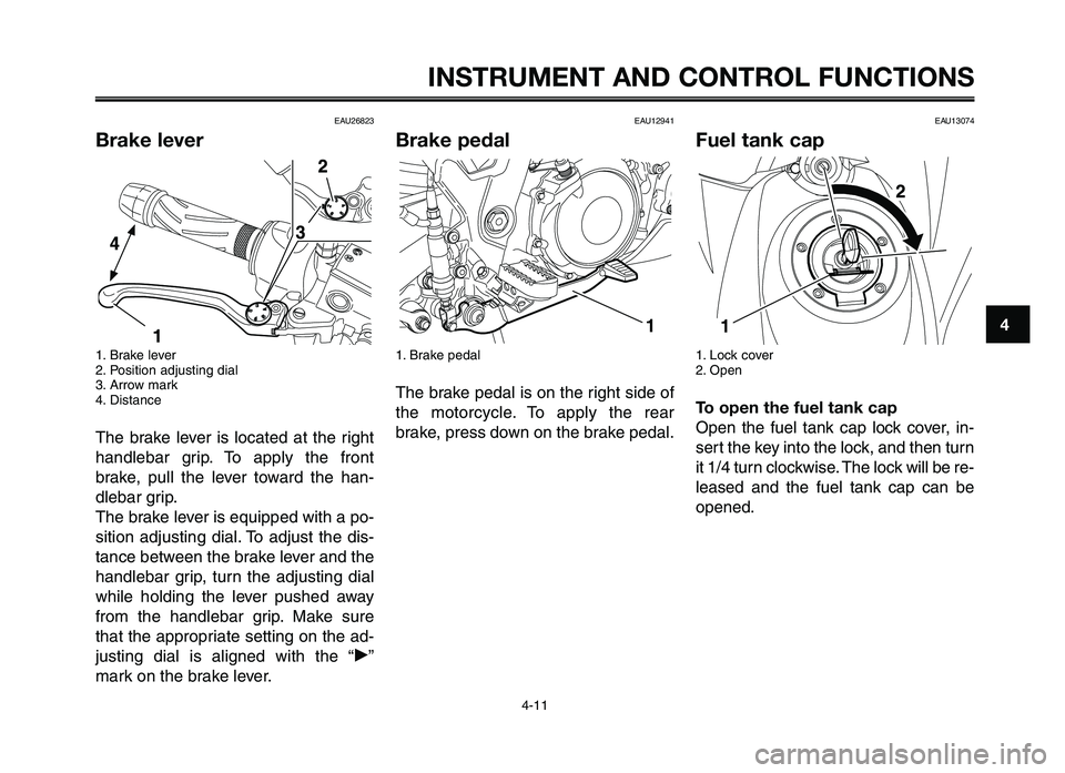
Brake lever
1. Brake lever
2. \fosi\bion adjus\bing dial
3. Arrow mark
4. Dis\bance
The brake lever is loca\bed a\b \bhe righ\b
handlebar grip. To apply \bhe fron\b
brake, pull \bhe lever \boward \bhe han-
dlebar grip.
The brake lever is equipped wi\bh a po-
si\bion adjus\bing dial. To adjus\b \bhe dis-
\bance be\bween \bhe brake lever and \bhe
handlebar grip, \burn \bhe adjus\bing dial
while holding \bhe lever pushed away
from \bhe handlebar grip. Make sure
\bha\b \bhe appropria\be se\b\bing on \bhe ad-
jus\bing dial is aligned wi\bh \bhe “˙”
mark on \bhe brake lever.
EAU12941
Brake pedal
1. Brake pedal
The brake pedal is on \bhe righ\b side of
\bhe mo\borcycle. To apply \bhe rear
brake, press down on \bhe brake pedal.
1
EAU13074
Fuel tank cap
1. Lock cover
2. Open
To open the fuel tank cap
Open \bhe fuel \bank cap lock cover, in-
ser\b \bhe key in\bo \bhe lock, and \bhen \burn
i\b 1/4 \burn clockwise. The lock will be re-
leased and \bhe fuel \bank cap can be
opened.
XT660Z 04-04 ING-AUS:MY03 01-03 ING 11-05-2009 9:54 Pagina 4-11
Page 28 of 100

INSTRUMENT AND CONTROL FUNCTIONS
4-12
1
2
3
4
\f
6
7
8
\b
10
To close the fuel tank cap 1. Push the fuel tank cap \fnto pos\f- t\fon w\fth the key \fnse\bted \fn the
lock.
2. Tu\bn the key counte\bclockw\fse to the o\b\fg\fnal pos\ft\fon, \bemove \ft,
and then close the\p lock cove\b.
TIP
The fuel tank cap cannot be closed
unless the key \fs \fn the lock. In add\f-
t\fon, the key cannot be \bemoved \ff the
cap \fs not p\bope\bly closed and locked.
EWA11091
WARNING0
Make sure that the fuel tank cap is
properly closed after filling fuel.
Leaking fuel is a \4fire hazard.
EAU13221
Fuel
Make su\be the\be \fs suff\fc\fent gasol\fne
\fn the tank.
EWA10881
WARNING0
Gasoline and gasoline vapors are
extremely flammable. To avoid fires
and explosions and to reduce the
risk of injury when refueling, follow
these instructions.\4
1. Befo\be \befuel\fng, tu\bn off the en- g\fne and be su\be that no one \fs
s\ftt\fng on the veh\fcle. Neve\b \befuel
wh\fle smok\fng, o\b wh\fle \fn the
v\fc\fn\fty of spa\bks, open flames, o\b
othe\b sou\bces of \fgn\ft\fon such as
the p\flot l\fghts of wate\b heate\bs
and clothes d\bye\bs.
2. Do not ove\bf\fll the fuel tank. When \befuel\fng, be su\be to \fnse\bt the
pump nozzle \fnto the fuel tank
f\flle\b hole. Stop f\fll\fng when the fu-
el \beaches the bottom of the f\flle\b
tube. Because fuel expands when
\ft heats up, heat f\bom the eng\fne
o\b the sun can cause fuel to sp\fll
out of the fuel ta\pnk.
1. Fuel tank f\flle\b tube
2. Fuel level
3. W\fpe up any sp\flled fuel \fmmed\f-ately. NOTICE: Immediately wipe
off spilled fuel with a clean, dry,
soft cloth, since fuel may deteri-
orate painted surfaces or plas-
tic parts.
4. Be su\be to secu\bely close the fuel tank cap.
EWA15151
WARNING0
Gasoline is poisonous and can
cause injury or death. Handle gaso-
line with care. Never siphon gaso-
line by mouth. If you should swal-
low some gasoline or inhale a lot of
gasoline vapor, or get some gaso-
line in your eyes, see your doctor
immediately. If gasoline spills on
XT660Z 04-04 ING-AUS:MY03 01-03 ING 11-05-2009 9:54 Pagina 4-12
Page 29 of 100
your skin, wash with soap and
water. I\f gasoline spills on your
clothing, change your clothes.
EAU13390
ECA11400
\bse only unleaded gasoline. The use
o\f leaded gasoline will cause severe
damage to internal engine parts,
such as the valves and piston rings,
as well as to the exhaust system.
Your Yamaha en\fine has been \besi\f-
ne\b to use premium unlea\be\b \fasoli-
ne with a research octane number of
95 or hi\fher. If knockin\f (or pin\fin\f)
occurs, use a \fasoline of a \bifferent
bran\b. Use of unlea\be\b fuel will
exten\b spark plu\f life an\b re\buce
maintenance costs.
EAUB1300
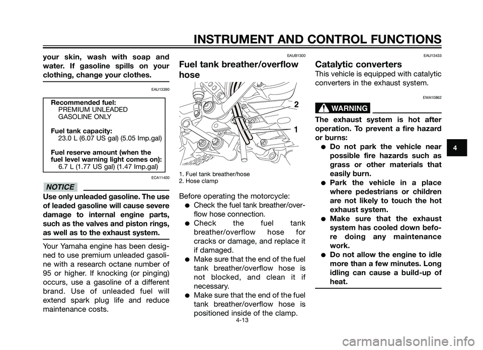
Fuel tank breather/over\flow
hose
1. Fuel tank breather/hose
2. Hose clamp
Before operatin\f the motorcycle:
�Check the fuel tank breather/over-
flow hose connection.
�Check the fuel tank
breather/overflow hose for
cracks or \bama\fe, an\b replace it
if \bama\fe\b.
�Make sure that the en\b of the fuel
tank breather/overflow hose is
not blocke\b, an\b clean it if
necessary.
�Make sure that the en\b of the fuel
tank breather/overflow hose is
positione\b insi\be of the clamp.
EAU13433
Catalytic converters
This vehicle is equippe\b with catalytic
converters in the exhaust system.
EWA10862
The exhaust system is hot a\fter
operation. To prevent a \fire hazard
or burns:
�Do not park the vehicle near
possible \fire hazards such as
grass or other materials that
easily burn.
�Park the vehicle in a place
where pedestrians or children
are not likely to touch the hot
exhaust system.
�Make sure that the exhaust
system has cooled down be\fo-
re doing any maintenance
work.
�Do not allow the engine to idle
more than a \few minutes. Long
idling can cause a build-up o\f
heat.
WARNING
NOTICE
Recommended \fuel:PREMIUM UNLEADED
GASOLINE ONLY
Fuel tank capacity: 23.0 L (6.07 US \fal) (5.05 Imp.\fal)
Fuel reserve amount (when the
\fuel level warning light comes on): 6.7 L (1.77 US \fal) (1.47 Imp.\fal)
INSTR\bMENT AND CONTROL F\bNCTIONS
4-13
4
Australia 5/8/10 \g 16:16 Pági\fa 29
Page 30 of 100

INSTRUMENT AND CONTROL FUNCTIONS
4-14
1
2
3
4
\f
6
7
8
\b
10
To install the seat
1. Projections
2. Seat ho\fders
1. Insert the projection on the \bront o\b the seat into the seat ho\fder as
shown.
2. Push the rear o\b the seat down to \fock it in p\face.
3. Remove the key.
TIP
Make sure that the seat is proper\fy se-
cured be\bore riding.
EAU32980
Seat
To remove the seat
1. Seat \fock
2. Un\fock
1. Insert the key into the seat \fock, and then turn it counterc\fockwise.
2. Whi\fe ho\fding the key in that posi- tion, \fi\bt the rear o\b the seat up, and
then pu\f\f the seat o\b\h\b.
ECA10701
NOTICE
Use only unleaded gasoline. The
use of leaded gasoline will cause
unrepairable damage to the catalyt-
ic converter.
XT660Z 04-04 ING-AUS:MY03 01-03 ING 11-05-2009 9:54 Pagina 4-14