check engine YAMAHA YZ250F 2016 Owner's Guide
[x] Cancel search | Manufacturer: YAMAHA, Model Year: 2016, Model line: YZ250F, Model: YAMAHA YZ250F 2016Pages: 356, PDF Size: 11.25 MB
Page 189 of 356
CHAIN DRIVE
4-65
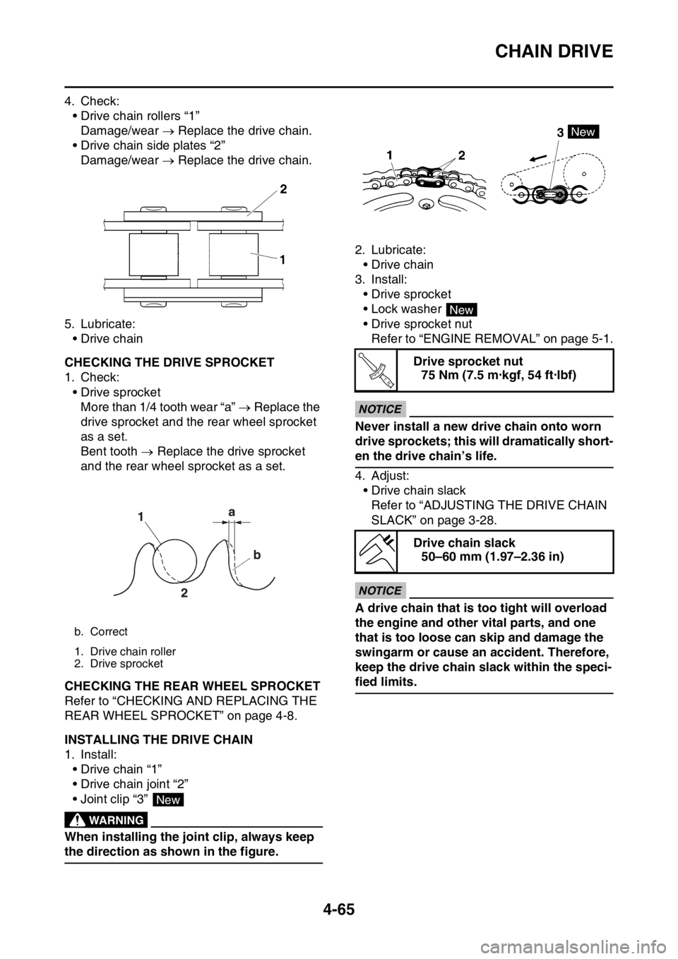
4. Check:
• Drive chain rollers “1”
Damage/wear Replace the drive chain.
• Drive chain side plates “2”
Damage/wear Replace the drive chain.
5. Lubricate:
•Drive chain
EAS1SM9190CHECKING THE DRIVE SPROCKET
1. Check:
• Drive sprocket
More than 1/4 tooth wear “a” Replace the
drive sprocket and the rear wheel sprocket
as a set.
Bent tooth Replace the drive sprocket
and the rear wheel sprocket as a set.
EAS1SM9191CHECKING THE REAR WHEEL SPROCKET
Refer to “CHECKING AND REPLACING THE
REAR WHEEL SPROCKET” on page 4-8.
EAS1SM9192INSTALLING THE DRIVE CHAIN
1. Install:
• Drive chain “1”
• Drive chain joint “2”
• Joint clip “3”
EWA
WARNING
When installing the joint clip, always keep
the direction as shown in the figure.2. Lubricate:
•Drive chain
3. Install:
• Drive sprocket
• Lock washer
• Drive sprocket nut
Refer to “ENGINE REMOVAL” on page 5-1.
ECA1DX1014
NOTICE
Never install a new drive chain onto worn
drive sprockets; this will dramatically short-
en the drive chain’s life.
4. Adjust:
• Drive chain slack
Refer to “ADJUSTING THE DRIVE CHAIN
SLACK” on page 3-28.
ECA13550
NOTICE
A drive chain that is too tight will overload
the engine and other vital parts, and one
that is too loose can skip and damage the
swingarm or cause an accident. Therefore,
keep the drive chain slack within the speci-
fied limits.
b. Correct
1. Drive chain roller
2. Drive sprocket
New
Drive sprocket nut
75 Nm (7.5 m·kgf, 54 ft·lbf)
Drive chain slack
50–60 mm (1.97–2.36 in)
New
T R..
Page 191 of 356
5
ENGINE
ENGINE REMOVAL......................................................................................... 5-1
REMOVING THE SILENCER ..................................................................... 5-6
REMOVING THE EXHAUST PIPE 2.......................................................... 5-6
REMOVING THE DRIVE SPROCKET ....................................................... 5-6
REMOVING THE ENGINE ......................................................................... 5-7
CHECKING THE SILENCER AND EXHAUST PIPE.................................. 5-7
CHANGING THE SILENCER FIBER ......................................................... 5-7
INSTALLING THE ENGINE........................................................................ 5-8
INSTALLING THE BRAKE PEDAL ............................................................ 5-9
INSTALLING THE DRIVE SPROCKET...................................................... 5-9
INSTALLING THE EXHAUST PIPE AND MUFFLER............................... 5-10
CAMSHAFT.................................................................................................... 5-11
REMOVING THE CAMSHAFT ................................................................. 5-13
CHECKING THE CAMSHAFT.................................................................. 5-14
CHECKING THE TIMING CHAIN AND CAMSHAFT SPROCKET .......... 5-15
CHECKING THE TIMING CHAIN TENSIONERS .................................... 5-15
CHECKING THE DECOMPRESSION SYSTEM...................................... 5-16
INSTALLING THE CAMSHAFTS ............................................................. 5-16
CYLINDER HEAD........................................................................................... 5-18
REMOVING THE CYLINDER HEAD........................................................ 5-20
CHECKING THE TIMING CHAIN GUIDE (INTAKE SIDE) ...................... 5-20
CHECKING THE CYLINDER HEAD ........................................................ 5-20
INSTALLING THE CYLINDER HEAD ...................................................... 5-21
VALVES AND VALVE SPRINGS................................................................... 5-22
REMOVING THE VALVES ....................................................................... 5-23
CHECKING THE VALVES AND VALVE GUIDES ................................... 5-24
CHECKING THE VALVE SEATS ............................................................. 5-25
CHECKING THE VALVE SPRINGS......................................................... 5-27
CHECKING THE VALVE LIFTERS .......................................................... 5-28
INSTALLING THE VALVES ..................................................................... 5-28
CYLINDER AND PISTON............................................................................... 5-30
REMOVING THE PISTON ....................................................................... 5-31
CHECKING THE CYLINDER AND PISTON ............................................ 5-31
CHECKING THE PISTON RINGS............................................................ 5-32
CHECKING THE PISTON PIN ................................................................. 5-33
INSTALLING THE PISTON AND CYLINDER .......................................... 5-33
Page 200 of 356
ENGINE REMOVAL
5-7
EAS1SM9198REMOVING THE ENGINE
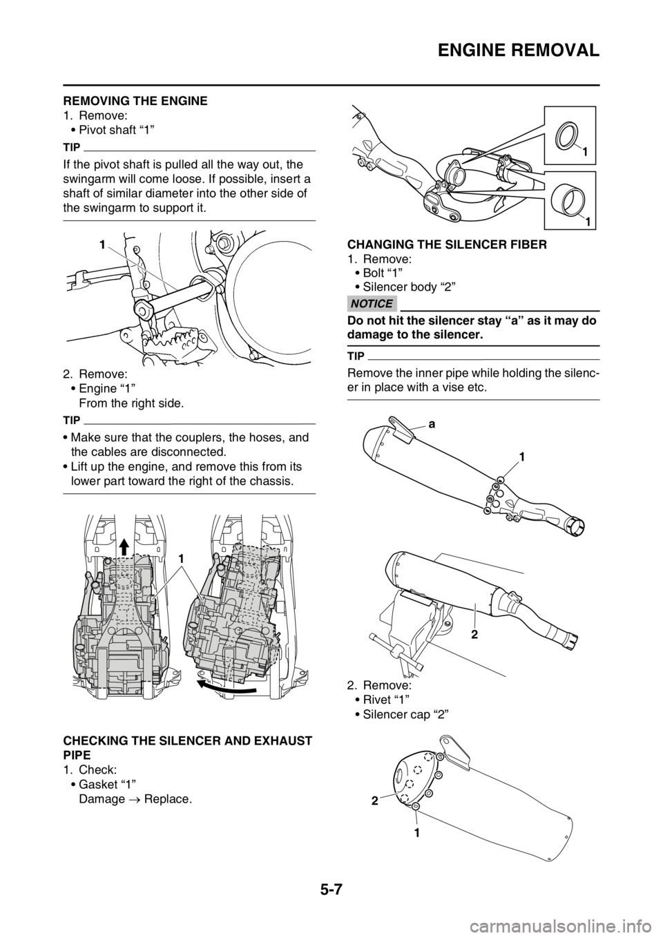
1. Remove:
• Pivot shaft “1”
TIP
If the pivot shaft is pulled all the way out, the
swingarm will come loose. If possible, insert a
shaft of similar diameter into the other side of
the swingarm to support it.
2. Remove:
• Engine “1”
From the right side.
TIP
• Make sure that the couplers, the hoses, and
the cables are disconnected.
• Lift up the engine, and remove this from its
lower part toward the right of the chassis.
EAS1SM9199CHECKING THE SILENCER AND EXHAUST
PIPE
1. Check:
•Gasket “1”
Damage Replace.
EAS1SM9200CHANGING THE SILENCER FIBER
1. Remove:
•Bolt “1”
• Silencer body “2”
ECANOTICE
Do not hit the silencer stay “a” as it may do
damage to the silencer.
TIP
Remove the inner pipe while holding the silenc-
er in place with a vise etc.
2. Remove:
•Rivet “1”
• Silencer cap “2”
1
1
1
a
1
2
2
1
Page 203 of 356
ENGINE REMOVAL
5-10
EAS1SM9204INSTALLING THE EXHAUST PIPE AND
MUFFLER
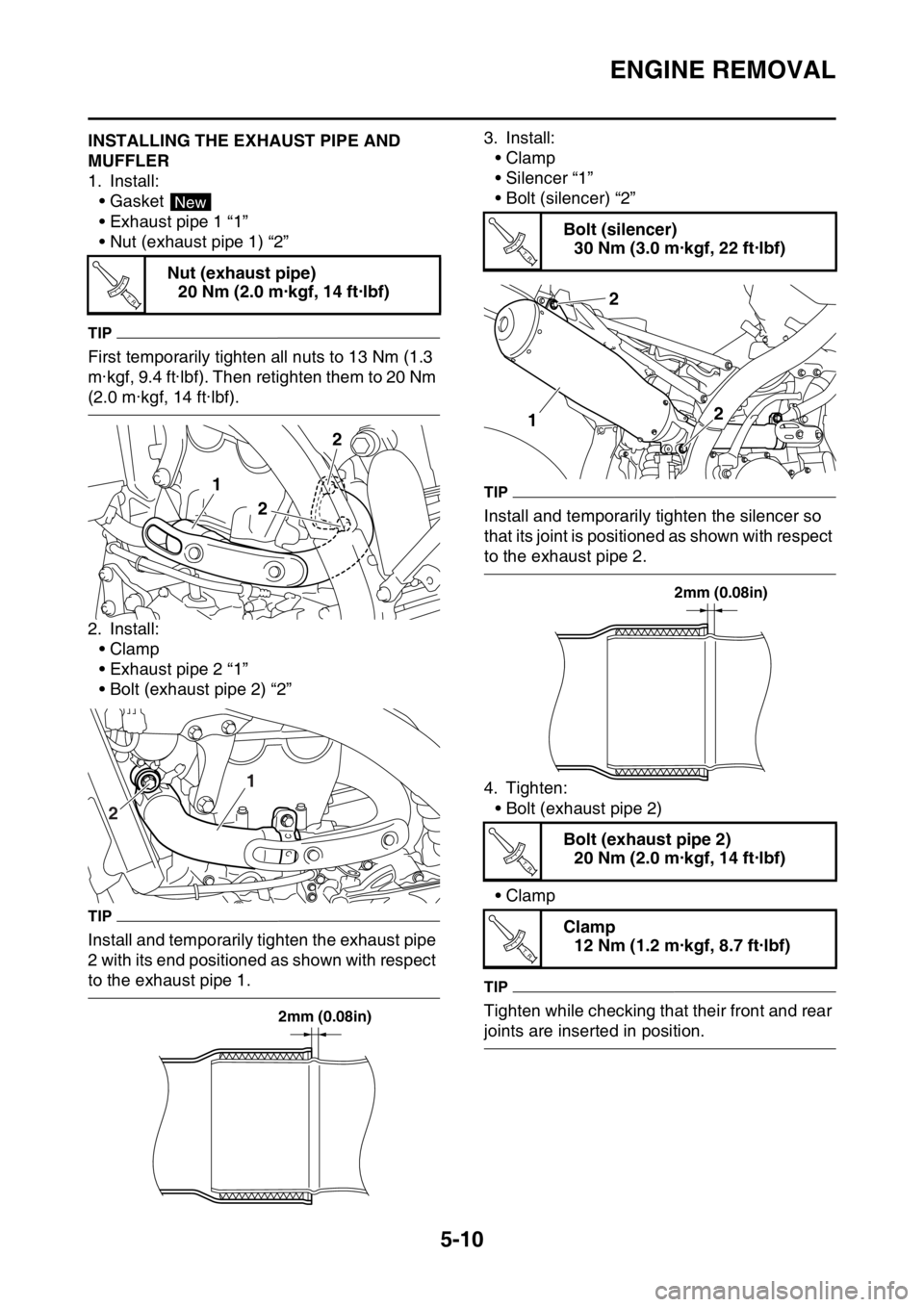
1. Install:
•Gasket
• Exhaust pipe 1 “1”
• Nut (exhaust pipe 1) “2”
TIP
First temporarily tighten all nuts to 13 Nm (1.3
m·kgf, 9.4 ft·lbf). Then retighten them to 20 Nm
(2.0 m·kgf, 14 ft·lbf).
2. Install:
•Clamp
• Exhaust pipe 2 “1”
• Bolt (exhaust pipe 2) “2”
TIP
Install and temporarily tighten the exhaust pipe
2 with its end positioned as shown with respect
to the exhaust pipe 1.3. Install:
•Clamp
• Silencer “1”
• Bolt (silencer) “2”
TIP
Install and temporarily tighten the silencer so
that its joint is positioned as shown with respect
to the exhaust pipe 2.
4. Tighten:
• Bolt (exhaust pipe 2)
•Clamp
TIP
Tighten while checking that their front and rear
joints are inserted in position. Nut (exhaust pipe)
20 Nm (2.0 m·kgf, 14 ft·lbf)
New
T R..
1
22
1
2
2mm (0.08in)
Bolt (silencer)
30 Nm (3.0 m·kgf, 22 ft·lbf)
Bolt (exhaust pipe 2)
20 Nm (2.0 m·kgf, 14 ft·lbf)
Clamp
12 Nm (1.2 m·kgf, 8.7 ft·lbf)
T R..
2
2
1
2mm (0.08in)
T R..
T R..
Page 209 of 356
CAMSHAFT
5-16
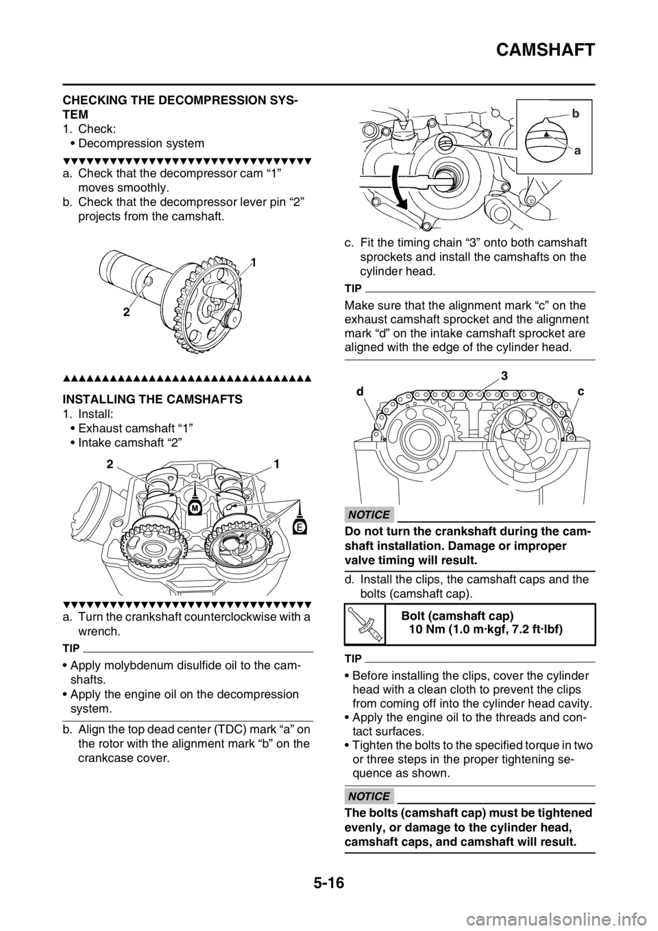
EAS1SM9210CHECKING THE DECOMPRESSION SYS-
TEM
1. Check:
• Decompression system
▼▼▼▼▼▼▼▼▼▼▼▼▼▼▼▼▼▼▼▼▼▼▼▼▼▼▼▼▼▼▼▼
a. Check that the decompressor cam “1”
moves smoothly.
b. Check that the decompressor lever pin “2”
projects from the camshaft.
▲▲▲▲▲▲▲▲▲▲▲▲▲▲▲▲▲▲▲▲▲▲▲▲▲▲▲▲▲▲▲▲
EAS1SM9211INSTALLING THE CAMSHAFTS
1. Install:
• Exhaust camshaft “1”
• Intake camshaft “2”
▼▼▼▼▼▼▼▼▼▼▼▼▼▼▼▼▼▼▼▼▼▼▼▼▼▼▼▼▼▼▼▼
a. Turn the crankshaft counterclockwise with a
wrench.
TIP
• Apply molybdenum disulfide oil to the cam-
shafts.
• Apply the engine oil on the decompression
system.
b. Align the top dead center (TDC) mark “a” on
the rotor with the alignment mark “b” on the
crankcase cover.c. Fit the timing chain “3” onto both camshaft
sprockets and install the camshafts on the
cylinder head.
TIP
Make sure that the alignment mark “c” on the
exhaust camshaft sprocket and the alignment
mark “d” on the intake camshaft sprocket are
aligned with the edge of the cylinder head.
ECA33DD029NOTICE
Do not turn the crankshaft during the cam-
shaft installation. Damage or improper
valve timing will result.
d. Install the clips, the camshaft caps and the
bolts (camshaft cap).
TIP
• Before installing the clips, cover the cylinder
head with a clean cloth to prevent the clips
from coming off into the cylinder head cavity.
• Apply the engine oil to the threads and con-
tact surfaces.
• Tighten the bolts to the specified torque in two
or three steps in the proper tightening se-
quence as shown.
ECA33DD030NOTICE
The bolts (camshaft cap) must be tightened
evenly, or damage to the cylinder head,
camshaft caps, and camshaft will result.
1
2
Bolt (camshaft cap)
10 Nm (1.0 m·kgf, 7.2 ft·lbf)
b
a
dc
3
T R..
Page 233 of 356
CLUTCH
5-40
EAS1SM9241CHECKING THE PRIMARY DRIVEN GEAR
1. Check:
• Primary driven gear
Damage/wear Replace the primary drive
and primary driven gears as a set.
Excessive noise during operation Re-
place the primary drive and primary driven
gears as a set.
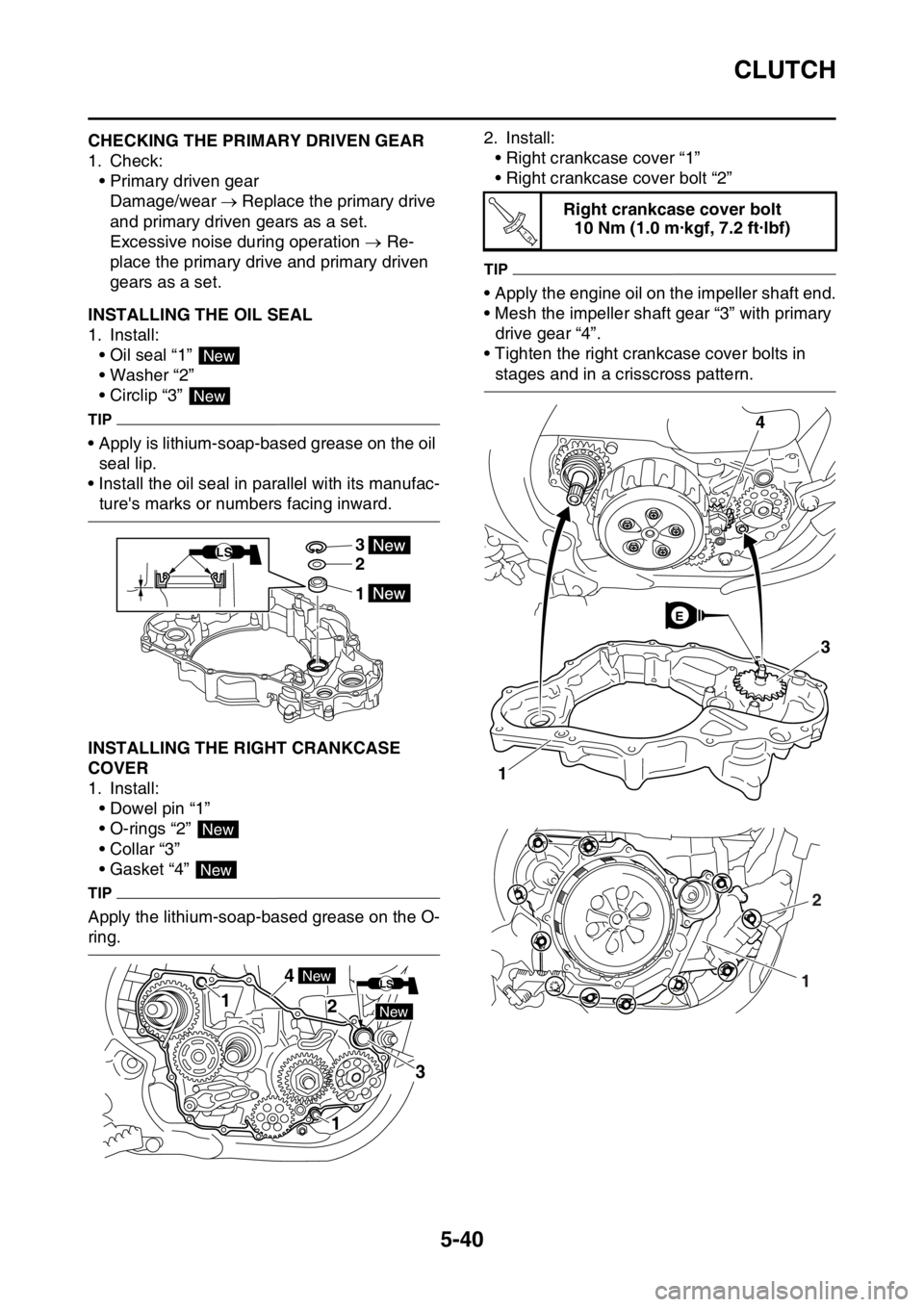
EAS1SM9242INSTALLING THE OIL SEAL
1. Install:
• Oil seal “1”
• Washer “2”
• Circlip “3”
TIP
• Apply is lithium-soap-based grease on the oil
seal lip.
• Install the oil seal in parallel with its manufac-
ture's marks or numbers facing inward.
EAS1SM9243INSTALLING THE RIGHT CRANKCASE
COVER
1. Install:
• Dowel pin “1”
• O-rings “2”
• Collar “3”
• Gasket “4”
TIP
Apply the lithium-soap-based grease on the O-
ring.2. Install:
• Right crankcase cover “1”
• Right crankcase cover bolt “2”
TIP
• Apply the engine oil on the impeller shaft end.
• Mesh the impeller shaft gear “3” with primary
drive gear “4”.
• Tighten the right crankcase cover bolts in
stages and in a crisscross pattern.
New
New
3
2
1
LS
New
New
1
1 4
2
New
New
3
LS
Right crankcase cover bolt
10 Nm (1.0 m·kgf, 7.2 ft·lbf)
T R..
3
1
4
E
12
Page 248 of 356
OIL PUMP AND BALANCER GEAR
5-55
3. Check:
• Oil pump operation
Rough movement Repeat steps (1) and
(2) or replace the defective part(s).
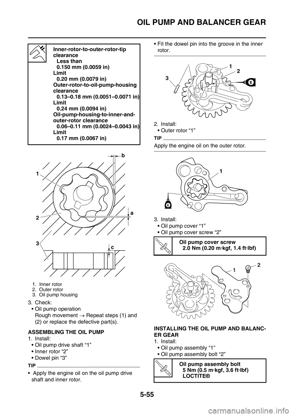
EAS1SM9268ASSEMBLING THE OIL PUMP
1. Install:
• Oil pump drive shaft “1”
• Inner rotor “2”
• Dowel pin “3”
TIP
• Apply the engine oil on the oil pump drive
shaft and inner rotor.• Fit the dowel pin into the groove in the inner
rotor.
2. Install:
• Outer rotor “1”
TIP
Apply the engine oil on the outer rotor.
3. Install:
• Oil pump cover “1”
• Oil pump cover screw “2”
EAS1SM9269INSTALLING THE OIL PUMP AND BALANC-
ER GEAR
1. Install:
• Oil pump assembly “1”
• Oil pump assembly bolt “2” Inner-rotor-to-outer-rotor-tip
clearance
Less than
0.150 mm (0.0059 in)
Limit
0.20 mm (0.0079 in)
Outer-rotor-to-oil-pump-housing
clearance
0.13–0.18 mm (0.0051–0.0071 in)
Limit
0.24 mm (0.0094 in)
Oil-pump-housing-to-inner-and-
outer-rotor clearance
0.06–0.11 mm (0.0024–0.0043 in)
Limit
0.17 mm (0.0067 in)
1. Inner rotor
2. Outer rotor
3. Oil pump housing
b
a 1
2
3
c
Oil pump cover screw
2.0 Nm (0.20 m·kgf, 1.4 ft·lbf)
Oil pump assembly bolt
5 Nm (0.5 m·kgf, 3.6 ft·lbf)
LOCTITE®
21
3
1
E
T R..
2
1
T R..
Page 257 of 356
CRANKCASE
5-64
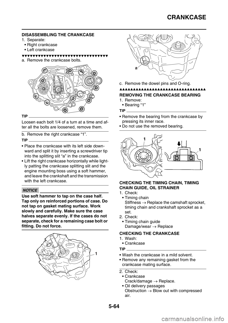
EAS1SM9276DISASSEMBLING THE CRANKCASE
1. Separate:
• Right crankcase
• Left crankcase
▼▼▼▼▼▼▼▼▼▼▼▼▼▼▼▼▼▼▼▼▼▼▼▼▼▼▼▼▼▼▼▼
a. Remove the crankcase bolts.
TIP
Loosen each bolt 1/4 of a turn at a time and af-
ter all the bolts are loosened, remove them.
b. Remove the right crankcase “1”.
TIP
• Place the crankcase with its left side down-
ward and split it by inserting a screwdriver tip
into the splitting slit “a” in the crankcase.
• Lift the right crankcase horizontally while light-
ly patting the crankcase splitting slit and the
engine mounting boss using a soft hammer,
and leave the crankshaft and the transmission
with the left crankcase.
ECA
NOTICE
Use soft hammer to tap on the case half.
Tap only on reinforced portions of case. Do
not tap on gasket mating surface. Work
slowly and carefully. Make sure the case
halves separate evenly. If the cases do not
separate, check for a remaining case bolt or
fitting. Do not force.c. Remove the dowel pins and O-ring.
▲▲▲▲▲▲▲▲▲▲▲▲▲▲▲▲▲▲▲▲▲▲▲▲▲▲▲▲▲▲▲▲EAS1SM9277REMOVING THE CRANKCASE BEARING
1. Remove:
• Bearing “1”
TIP
• Remove the bearing from the crankcase by
pressing its inner race.
• Do not use the removed bearing.
EAS1SM9278CHECKING THE TIMING CHAIN, TIMING
CHAIN GUIDE, OIL STRAINER
1. Check:
• Timing chain
Stiffness Replace the camshaft sprocket,
timing chain and crankshaft sprocket as a
set.
2. Check:
• Timing chain guide
Damage/wear Replace
EAS1SM9279CHECKING THE CRANKCASE
1. Wash:
• Crankcase
TIP
• Wash the crankcase in a mild solvent.
• Remove any remaining gasket from the
crankcase mating surface.
2. Check:
• Crankcase
Crack/damage Replace.
• Oil delivery passages
Obstruction Blow out with compressed
air.
1
a
Page 266 of 356
TRANSMISSION
5-73
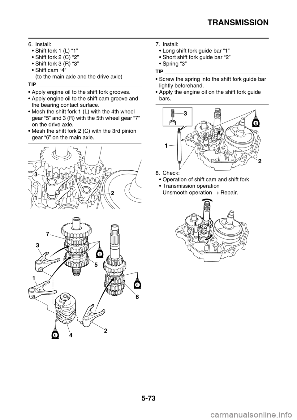
6. Install:
• Shift fork 1 (L) “1”
• Shift fork 2 (C) “2”
• Shift fork 3 (R) “3”
• Shift cam “4”
(to the main axle and the drive axle)
TIP
• Apply engine oil to the shift fork grooves.
• Apply engine oil to the shift cam groove and
the bearing contact surface.
• Mesh the shift fork 1 (L) with the 4th wheel
gear “5” and 3 (R) with the 5th wheel gear “7”
on the drive axle.
• Mesh the shift fork 2 (C) with the 3rd pinion
gear “6” on the main axle.7. Install:
• Long shift fork guide bar “1”
• Short shift fork guide bar “2”
• Spring “3”
TIP
• Screw the spring into the shift fork guide bar
lightly beforehand.
• Apply the engine oil on the shift fork guide
bars.
8. Check:
• Operation of shift cam and shift fork
• Transmission operation
Unsmooth operation Repair.
3
12
6
24
5
3
7
1
E
E
E
2 13
E
Page 273 of 356
WATER PUMP
6-6
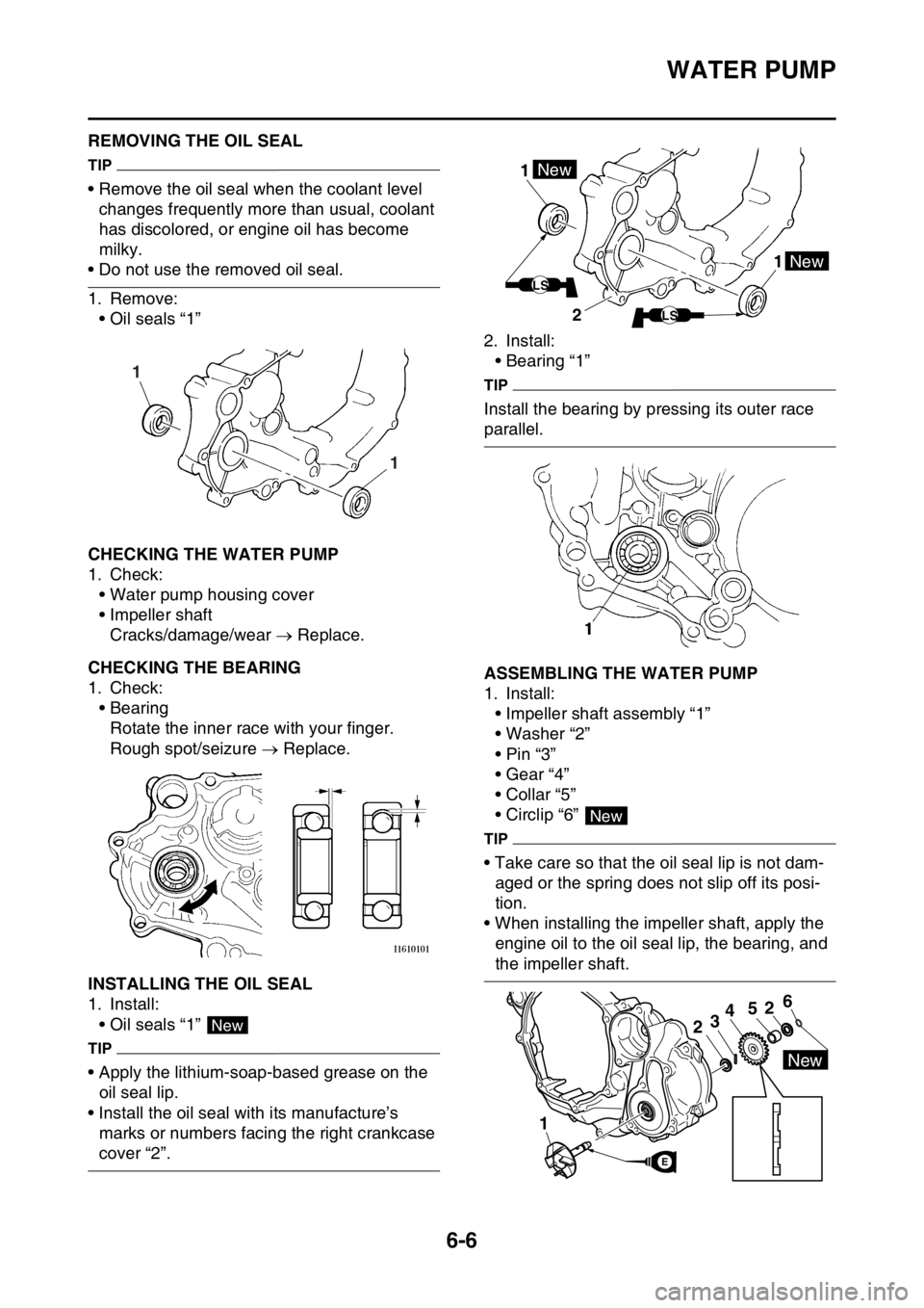
EAS1SM9298REMOVING THE OIL SEAL
TIP
• Remove the oil seal when the coolant level
changes frequently more than usual, coolant
has discolored, or engine oil has become
milky.
• Do not use the removed oil seal.
1. Remove:
• Oil seals “1”
EAS1SM9299CHECKING THE WATER PUMP
1. Check:
• Water pump housing cover
• Impeller shaft
Cracks/damage/wear Replace.
EAS1SM9300CHECKING THE BEARING
1. Check:
• Bearing
Rotate the inner race with your finger.
Rough spot/seizure Replace.
EAS1SM9301INSTALLING THE OIL SEAL
1. Install:
• Oil seals “1”
TIP
• Apply the lithium-soap-based grease on the
oil seal lip.
• Install the oil seal with its manufacture’s
marks or numbers facing the right crankcase
cover “2”.2. Install:
• Bearing “1”
TIP
Install the bearing by pressing its outer race
parallel.
EAS1SM9302ASSEMBLING THE WATER PUMP
1. Install:
• Impeller shaft assembly “1”
• Washer “2”
•Pin “3”
• Gear “4”
• Collar “5”
• Circlip “6”
TIP
• Take care so that the oil seal lip is not dam-
aged or the spring does not slip off its posi-
tion.
• When installing the impeller shaft, apply the
engine oil to the oil seal lip, the bearing, and
the impeller shaft.
1 1
New
1 1New
New
LS
LS2
New
1
2
52346
New
E